EP0807401A1 - Improved medical monitoring probe - Google Patents
Improved medical monitoring probe Download PDFInfo
- Publication number
- EP0807401A1 EP0807401A1 EP97302683A EP97302683A EP0807401A1 EP 0807401 A1 EP0807401 A1 EP 0807401A1 EP 97302683 A EP97302683 A EP 97302683A EP 97302683 A EP97302683 A EP 97302683A EP 0807401 A1 EP0807401 A1 EP 0807401A1
- Authority
- EP
- European Patent Office
- Prior art keywords
- light
- light emitting
- electronics assembly
- emitting means
- probe
- Prior art date
- Legal status (The legal status is an assumption and is not a legal conclusion. Google has not performed a legal analysis and makes no representation as to the accuracy of the status listed.)
- Withdrawn
Links
- 239000000523 sample Substances 0.000 title claims abstract description 63
- 238000012544 monitoring process Methods 0.000 title description 4
- 239000000463 material Substances 0.000 claims abstract description 13
- 230000003287 optical effect Effects 0.000 claims abstract description 4
- 239000004020 conductor Substances 0.000 claims description 13
- 239000008280 blood Substances 0.000 claims description 12
- 210000004369 blood Anatomy 0.000 claims description 12
- 230000005540 biological transmission Effects 0.000 claims description 3
- 230000031700 light absorption Effects 0.000 claims description 3
- 230000013011 mating Effects 0.000 claims description 3
- 238000004891 communication Methods 0.000 claims description 2
- 238000004519 manufacturing process Methods 0.000 abstract description 23
- 239000004593 Epoxy Substances 0.000 abstract description 17
- 230000000712 assembly Effects 0.000 abstract description 3
- 238000000429 assembly Methods 0.000 abstract description 3
- 230000010354 integration Effects 0.000 abstract description 3
- 238000000034 method Methods 0.000 description 7
- QVGXLLKOCUKJST-UHFFFAOYSA-N atomic oxygen Chemical compound [O] QVGXLLKOCUKJST-UHFFFAOYSA-N 0.000 description 5
- 239000011248 coating agent Substances 0.000 description 5
- 238000000576 coating method Methods 0.000 description 5
- 229910052760 oxygen Inorganic materials 0.000 description 5
- 239000001301 oxygen Substances 0.000 description 5
- 210000001519 tissue Anatomy 0.000 description 5
- 238000010521 absorption reaction Methods 0.000 description 4
- 230000008569 process Effects 0.000 description 4
- 230000000541 pulsatile effect Effects 0.000 description 4
- 102000001554 Hemoglobins Human genes 0.000 description 3
- 108010054147 Hemoglobins Proteins 0.000 description 3
- 238000013461 design Methods 0.000 description 3
- BQCADISMDOOEFD-UHFFFAOYSA-N Silver Chemical compound [Ag] BQCADISMDOOEFD-UHFFFAOYSA-N 0.000 description 2
- 238000010586 diagram Methods 0.000 description 2
- 238000005259 measurement Methods 0.000 description 2
- 238000002310 reflectometry Methods 0.000 description 2
- 229910052709 silver Inorganic materials 0.000 description 2
- 239000004332 silver Substances 0.000 description 2
- 229920004142 LEXAN™ Polymers 0.000 description 1
- 230000008321 arterial blood flow Effects 0.000 description 1
- 230000017531 blood circulation Effects 0.000 description 1
- 210000000988 bone and bone Anatomy 0.000 description 1
- 230000008859 change Effects 0.000 description 1
- 150000001875 compounds Chemical class 0.000 description 1
- 210000000624 ear auricle Anatomy 0.000 description 1
- 238000000465 moulding Methods 0.000 description 1
- 210000000492 nasalseptum Anatomy 0.000 description 1
- 229920000515 polycarbonate Polymers 0.000 description 1
- 239000004417 polycarbonate Substances 0.000 description 1
- 238000004382 potting Methods 0.000 description 1
- 230000009467 reduction Effects 0.000 description 1
- 210000002345 respiratory system Anatomy 0.000 description 1
- 238000005070 sampling Methods 0.000 description 1
- 239000007787 solid Substances 0.000 description 1
Images


Classifications
-
- A—HUMAN NECESSITIES
- A61—MEDICAL OR VETERINARY SCIENCE; HYGIENE
- A61B—DIAGNOSIS; SURGERY; IDENTIFICATION
- A61B5/00—Measuring for diagnostic purposes; Identification of persons
- A61B5/145—Measuring characteristics of blood in vivo, e.g. gas concentration or pH-value ; Measuring characteristics of body fluids or tissues, e.g. interstitial fluid or cerebral tissue
- A61B5/1455—Measuring characteristics of blood in vivo, e.g. gas concentration or pH-value ; Measuring characteristics of body fluids or tissues, e.g. interstitial fluid or cerebral tissue using optical sensors, e.g. spectral photometrical oximeters
- A61B5/14551—Measuring characteristics of blood in vivo, e.g. gas concentration or pH-value ; Measuring characteristics of body fluids or tissues, e.g. interstitial fluid or cerebral tissue using optical sensors, e.g. spectral photometrical oximeters for measuring blood gases
- A61B5/14552—Details of sensors specially adapted therefor
-
- A—HUMAN NECESSITIES
- A61—MEDICAL OR VETERINARY SCIENCE; HYGIENE
- A61B—DIAGNOSIS; SURGERY; IDENTIFICATION
- A61B2562/00—Details of sensors; Constructional details of sensor housings or probes; Accessories for sensors
- A61B2562/08—Sensors provided with means for identification, e.g. barcodes or memory chips
Definitions
- This invention relates to medical monitoring probes and, in particular, to a probe having a housing which is constructed of modular elements which function to enclose and encapsulate a lead frame on which is mounted the active and passive electronics elements.
- the manufacturing and assembly of the probe is a fairly labor intensive operation with the worker having to electrically interconnect the various components to the wiring contained within the probe and then place the assembled wiring in a portion of the housing that encapsulates the probe.
- This partially assembled probe requires the addition of one or more additional housing elements to complete the assembly thereof.
- This present method of assembling probes and the probe design used in this process produce high quality probes but are relatively expensive to manufacture.
- a reduction in the number of elements required to manufacture a probe and/or a simplification of the manufacturing process in assembling the probe can represent significant cost savings to the probe manufacturer. Therefore, minor advances in probe architecture and manufacturing techniques reap large benefits.
- an electronics assembly of light emitting devices for use in a probe module, affixable to an appendage of a patient, for illuminating perfused tissue in said appendage to measure light absorption of blood analytes contained in said perfused tissue, comprises:
- This probe makes use of a device housing which is assembled with a minimal number of modular pieces to enclose wiring and electronics that are mounted on a lead frame to create a unitary structure that simplifies the manufacture of the probe.
- a simplified modular device housing structure the cost of the probe is significantly reduced since the entire device housing of the probe consists of interlocking molded elements.
- the manufacture of the electronics component of the probe is simplified by using an integral lead frame on which is mounted all of the passive and active elements so that the entire electronics module can be assembled independent of the housing in a simplified form prior to integration into the housing.
- the lead frame provides not only the electrical interconnections but the support and positioning of the various light emitting and coding elements that comprise the electronics of the probe.
- the remaining segment of the manufacturing process is simplified since the workers do not have to assemble multiple diverse elements to create the device housing.
- the light reflecting and lens assemblies lock together and enclose an epoxy material which encapsulates the electronics elements and provides improved optical transmissivity of the generated light.
- the assembly of the probe is therefore reduced to placement of the various elements on the lead frame and the bonding of these elements together to form the integral electronics structure which is then placed in one of the modular device housings in the position defined by the layout of the housing so that the elements of the integral lead frame are precisely positioned therein.
- This simplified, efficient method of manufacture with reduced number of parts reduces the costs of the probe by minimizing the labor content and the assembly thereof and reducing the cost of the components used to manufacture the probe.
- the apparatus of the present invention consists of a device housing which is assembled with a minimal number of modular pieces to enclose wiring and electronics that are mounted on a lead frame to create a unitary structure that simplifies the manufacture of the probe
- a pulse oximeter instrument is frequently used to monitor the condition of a patient in a hospital setting.
- the pulse oximeter instrument noninvasively measures the oxygen saturation of the arterial blood and produces a human readable display that indicates both the patient's heart rate and the oxygen saturation of the arterial blood. These readings are important to enable the medical staff to determine whether the patient's respiratory system is functioning properly, supplying sufficient oxygen to the blood.
- a pulse oximeter instrument operates by use of a probe that transilluminates an appendage of the patient (such as a finger, earlobe, or the nasal septum) that is rich in arterial blood and measuring the amount of light that is absorbed by the pulsatile portion of the arterial blood to thereby determine oxygen saturation of the arterial blood.
- the pulse oximeter instrument makes use of a plurality of light-emitting devices, each of which transmits light at a predetermined wavelength, which wavelengths are selected such that at least one is highly absorbed by oxygenated hemoglobin in the arterial blood and at least one is highly absorbed by reduced hemoglobin in the arterial blood.
- the amount of absorption of the light beams generated by these light emitting devices that are located in the probe is a measure of the relative concentration of the oxygenated and reduced hemoglobin in the arterial blood.
- the absorption of the light that is being transmitted through the appendage of the patient includes a constant portion that is a result of skin, bone, steady-state (venous) blood flow and light loss due to various other factors.
- the pulsatile component of absorption is due to the pulsatile arterial blood flow and is a small fraction of the received signal and is used by the pulse oximeter instrument to perform its measurements.
- the measurements are computed by periodically sampling the output of the light detector located in the probe to determine the incremental change in absorption of the various wavelengths of light transmitted through the appendage of the patient. These incremental changes in light absorption are then used to compute the oxygen saturation of the arterial blood as well as the patient's pulse rate. Since the pulsatile component of the signals received by the light detector represent only a small fraction of the incident light, it is important that the incident light be of significant magnitude to result in transmitted signals that have sufficient amplitude to provide accurate readings. In addition, the light-emitting devices and the light detector must be placed in intimate contact with the skin of the patient on opposite sides of the appendage (or on the same side of the appendage in reflectance probes) to obtain the most accurate readings.
- the probe design must therefore be such that it inherently accommodates variations in size and shape of the patient's appendage and also enables the medical staff to simply align the probe to obtain the maximum readings. These stringent requirements are difficult for existing probes to comply with and increase the manufacturing cost of the probes, which may be disposable elements.
- Figure 1 illustrates a perspective exploded view of the electronics assembly portion of the probe P of the present invention.
- the electronics assembly is attached to a connector shell element 11 which is a portion of the probe housing.
- the connector shell element 11 includes a plurality of holes formed therein to receive a number of pins 15 which comprise the electrical conductors of the connector.
- the pins 15 are typically molded into the connector shell element 11 to insure their precise positioning and secure mounting therein.
- a lead frame 3 formed of a plurality of conductors 8A-8H provides the electrical interconnection of the active and passive elements which comprise the electronics portion of the probe P.
- eight pins 15 are shown in Figure 1, but the number and precise placement of these elements are a function of the specific implementation of the electronics elements contained in the probe P.
- the eight pins 15 comprise a predetermined pattern of conductors which mate with a like number and configuration of apertures formed in the eight conductors 8A-8H of lead frame 3.
- the lead frame 3 therefore fits on top of the pins 15 and is soldered thereto.
- a plurality of light emitting devices At the other end of the lead frame 3, distal from the connector pins 15 are mounted a plurality of light emitting devices, with two light emitting devices 1, 2 being shown in Figure 1 as an illustration.
- the light emitting devices 1, 2 are each connected to two corresponding conductors 8C, 8D and 8E, 8F, respectively, of the lead frame 3.
- the light emitting devices 1, 2 are individually placed on top of a corresponding one of the lead frame conductors 8C, 8F on a mounting pad area contained therein.
- the other of the two electrical conductors 8D, 8E is connected to the light emitting devices 1, 2 by means of a wire bond 4A, 4B which are electrically connected to the light emitting device 1,2 at one end and a lead frame conductor 8D, 8E at the other end.
- the electronics subassembly comprising the lead frame 3 with the attached coding resistor 5 and the light emitting devices 1, 2 are joined with the light reflecting element 13 and lens assembly 14 elements to form the electronics assembly, as shown in side view in Figure 3.
- the light reflecting element 13 is added to this subassembly to increase the light transmissivity of the assembly, as is shown by the side cross-section view of Figure 4.
- the light reflector 13 is a block of material having an aperture formed therein which is in the form of a geometrically shaped section which serves to receive light from the light emitting devices 1,2 of the probe P and redirect this light in the direction of the perfused tissue to be illuminated, as shown in Figure 4 by the plurality of lines representative of rays of light emitted by the light emitting devices 1,2.
- the shape of the aperture formed in the light reflective element 13 can be any shape which functions as described and can be selected from the geometric shapes including, but not limited to: truncated conical section, semispherical section, elliptical section, flat angle.
- the truncated conical section is used, since this geometric shape has a high output and is low cost to manufacture.
- the light reflective element 13 comprises a polycarbonate molding having an interior conical surface of roughly 45°, on which conical face a silver coating is deposited.
- the silver coating also includes a dielectric overcoat, so that the surface reflectivity is optimized for 600-1000 nm to obtain 90% reflectivity of the light generated by the light emitting devices 1, 2.
- the light reflective element 13 is held in place by the application of a compound of clear epoxy which is placed inside of the cup formed by the light reflective element 13. This combination of elements is then placed in position over the lens assembly 14 which is oriented in an inverted position, and partially filled with clear epoxy.
- the lens assembly comprises a Lexan® material which has a light transmissivity characteristic that enables the majority of the light produced by the light emitting devices 1, 2 to be passes through the lens assembly 14.
- the subassembly is then placed on the epoxy filled lens 14, with this additional epoxy filling any voids so that the interstitial space between the light emitting devices 1, 2 and the interior surface of the lens assembly 14 is devoid of air space.
- the inverted assembly has a predetermined amount of clear epoxy added to the back side surface thereof to complete the potting process.
- the assembly is then treated to cure the epoxy and form a solid light transmissive fill for the probe P.
- the light emitting devices 1, 2 are secured in place by the epoxy fill and are also hermetically sealed therein, protected from the ambient environment.
- the shape of the light reflective element 13 and the lens assembly 14 are mating, such that the two elements fit precisely together.
- the lens assembly 14 includes a shoulder formed therein to conform to a ledge formed in the sensor housing. Thus, the shoulder formed in the lens assembly 14 mates with the ledge formed in the housing to precisely position the light emitting devices 1, 2 and provide an integral fit therebetween.
- a coating of epoxy material 7 is added to the lead frame 3 to protect and encapsulate the exposed electrical conductors 8A-8H.
- the coating of epoxy material 7 covers the configuration of connector pins 15 and may also optionally be used to cover the coding resistor 5. The extent of the coating of epoxy material 7 is typically limited by the shoulder S formed in the lead frame 3 adjacent to the connector pins 15.
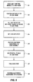
- the method of manufacturing the probe P is described in flow diagram form in Figure 5.
- This process comprises wire bonding the dies that contain light emitting devices 1, 2 to the lead frame 3 at step S1.
- the lead frame 3 is then quipped at step S2 with the light 18 April 1997 reflective element 13 and epoxy is added to the light reflective element 13 at step S3 to fill the light reflective element 13 and partially cured to adhere it in place on the lead frame 3.
- the lens assembly 14 is placed in a fixture (not shown) and epoxy added thereto.
- the lead frame subassembly is placed over the lens assembly 14 and, at step S6, epoxy is added to the exposed back surface of the lead frame 3 to ensure compete fill of the space within the probe electronics subassembly.
- the final curing of the epoxy is performed at step S7 and the assembly of the probe electronics is completed at step S8 with the placement of the electronics subassembly in the final probe housing.
- the manufacture of the electronics component of the probe is simplified by using an integral lead frame on which is mounted all of the passive and active elements so that the entire electronics module can be assembled independent of the housing in a simplified form prior to integration into the housing.
- the lead frame provides not only the electrical interconnections but the support and positioning of the various light emitting and coding elements that comprise the electronics of the probe.
- the remaining segment of the manufacturing process is simplified since the workers do not have to assemble multiple diverse elements to create the device housing.
- the light reflecting and lens assemblies lock together and enclose an epoxy material which encapsulates the electronics elements and provides improved optical transmissivity of the generated light. This structure and process can be used to form probes of different configuration and content.
- a coding resistor can be included in the probe, as is well known in the art, to define the light transmission characteristics of the light emitting devices via the impedance value of the coding resistor.
- more than two light emitting devices can be used in this probe design and the use of two devices is for the purpose of illustrating the concepts of the invention.
Landscapes
- Health & Medical Sciences (AREA)
- Physics & Mathematics (AREA)
- Life Sciences & Earth Sciences (AREA)
- Biomedical Technology (AREA)
- Medical Informatics (AREA)
- Biophysics (AREA)
- Pathology (AREA)
- Engineering & Computer Science (AREA)
- Spectroscopy & Molecular Physics (AREA)
- Heart & Thoracic Surgery (AREA)
- Optics & Photonics (AREA)
- Molecular Biology (AREA)
- Surgery (AREA)
- Animal Behavior & Ethology (AREA)
- General Health & Medical Sciences (AREA)
- Public Health (AREA)
- Veterinary Medicine (AREA)
- Measurement Of The Respiration, Hearing Ability, Form, And Blood Characteristics Of Living Organisms (AREA)
Abstract
The manufacture of the electronics component of the probe is simplified by using an integral lead frame on which is mounted all of the passive and active elements so that the entire electronics module can be assembled independent of the housing in a simplified form prior to integration into the housing. The lead frame provides not only the electrical interconnections but the support and positioning of the various light emitting elements that comprise the electronics of the probe. The remaining segment of the manufacturing process is simplified since the workers do not have to assemble multiple diverse elements to create the device housing. The light reflecting and lens assemblies lock together and enclose an epoxy material which encapsulates the electronics elements and provides improved optical transmissivity of the generated light.
Description
- This invention relates to medical monitoring probes and, in particular, to a probe having a housing which is constructed of modular elements which function to enclose and encapsulate a lead frame on which is mounted the active and passive electronics elements.
- It is a problem in the field of medical monitoring probes to manufacture a probe that is rugged, efficient, and yet inexpensive and simple to manufacture. It is important that the probe be either inexpensive so that it can be disposable after one use or able to be cleaned so that it can be used for many patient applications. If the probe is reusable, then the active elements contained therein that perform the sensing and measuring functions must be protected from the ambient environment. A significant factor that is relevant to probe manufacturing is that the cost of manufacture is proportional to the number of components that must be assembled to manufacture the probe. Existing hard shell probes typically comprise a plurality of different housing elements that must be assembled around the wiring and a number of discrete components that comprise the sensor electronics of the probe. Therefore, the manufacturing and assembly of the probe is a fairly labor intensive operation with the worker having to electrically interconnect the various components to the wiring contained within the probe and then place the assembled wiring in a portion of the housing that encapsulates the probe. This partially assembled probe requires the addition of one or more additional housing elements to complete the assembly thereof. This present method of assembling probes and the probe design used in this process produce high quality probes but are relatively expensive to manufacture. A reduction in the number of elements required to manufacture a probe and/or a simplification of the manufacturing process in assembling the probe can represent significant cost savings to the probe manufacturer. Therefore, minor advances in probe architecture and manufacturing techniques reap large benefits.
- The above described problems are solved and a technical advance achieved in the field by the medical monitoring probe of the present invention.
- According to the present invention, an electronics assembly of light emitting devices for use in a probe module, affixable to an appendage of a patient, for illuminating perfused tissue in said appendage to measure light absorption of blood analytes contained in said perfused tissue, comprises:
- a lead frame comprising a plurality of electrical conductors formed into a predetermined pattern;
- light emitting means mounted on said lead frame and in electrical communication with said electrical conductors;
- light reflective means mounted on said lead frame and encircling said light emitting means for directing beams of light generated by said light emitting means toward said perfused tissue; and
- lens means formed to mate with said light reflective means and mounted in mating fashion thereon for transmitting said beams of light generated by said light emitting means and reflected by said light reflective means toward said perfused tissue.
- This probe makes use of a device housing which is assembled with a minimal number of modular pieces to enclose wiring and electronics that are mounted on a lead frame to create a unitary structure that simplifies the manufacture of the probe. By making use of a simplified modular device housing structure, the cost of the probe is significantly reduced since the entire device housing of the probe consists of interlocking molded elements.
- The manufacture of the electronics component of the probe is simplified by using an integral lead frame on which is mounted all of the passive and active elements so that the entire electronics module can be assembled independent of the housing in a simplified form prior to integration into the housing. The lead frame provides not only the electrical interconnections but the support and positioning of the various light emitting and coding elements that comprise the electronics of the probe. The remaining segment of the manufacturing process is simplified since the workers do not have to assemble multiple diverse elements to create the device housing. The light reflecting and lens assemblies lock together and enclose an epoxy material which encapsulates the electronics elements and provides improved optical transmissivity of the generated light.
- The assembly of the probe is therefore reduced to placement of the various elements on the lead frame and the bonding of these elements together to form the integral electronics structure which is then placed in one of the modular device housings in the position defined by the layout of the housing so that the elements of the integral lead frame are precisely positioned therein. This simplified, efficient method of manufacture with reduced number of parts reduces the costs of the probe by minimizing the labor content and the assembly thereof and reducing the cost of the components used to manufacture the probe.
- An embodiment of the invention will now be described, by way of example, reference being made to the Figures of the accompanying diagrammatic drawings in which:-
- Figure 1 illustrates an exploded perspective view of the probe of the present invention;
- Figure 2 illustrates a top view of the light emitter assembly portion of the probe electronics assembly;
- Figure 3 illustrates a side view of the assembled electronics assembly;
- Figure 4 illustrates a side cross-section view of the light reflecting apparatus; and
- Figure 5 illustrates in flow diagram form the steps taken to assemble the probe.
- The apparatus of the present invention consists of a device housing which is assembled with a minimal number of modular pieces to enclose wiring and electronics that are mounted on a lead frame to create a unitary structure that simplifies the manufacture of the probe
- A pulse oximeter instrument is frequently used to monitor the condition of a patient in a hospital setting. The pulse oximeter instrument noninvasively measures the oxygen saturation of the arterial blood and produces a human readable display that indicates both the patient's heart rate and the oxygen saturation of the arterial blood. These readings are important to enable the medical staff to determine whether the patient's respiratory system is functioning properly, supplying sufficient oxygen to the blood.
- A pulse oximeter instrument operates by use of a probe that transilluminates an appendage of the patient (such as a finger, earlobe, or the nasal septum) that is rich in arterial blood and measuring the amount of light that is absorbed by the pulsatile portion of the arterial blood to thereby determine oxygen saturation of the arterial blood. The pulse oximeter instrument makes use of a plurality of light-emitting devices, each of which transmits light at a predetermined wavelength, which wavelengths are selected such that at least one is highly absorbed by oxygenated hemoglobin in the arterial blood and at least one is highly absorbed by reduced hemoglobin in the arterial blood. The amount of absorption of the light beams generated by these light emitting devices that are located in the probe is a measure of the relative concentration of the oxygenated and reduced hemoglobin in the arterial blood. The absorption of the light that is being transmitted through the appendage of the patient includes a constant portion that is a result of skin, bone, steady-state (venous) blood flow and light loss due to various other factors. The pulsatile component of absorption is due to the pulsatile arterial blood flow and is a small fraction of the received signal and is used by the pulse oximeter instrument to perform its measurements.
- The measurements are computed by periodically sampling the output of the light detector located in the probe to determine the incremental change in absorption of the various wavelengths of light transmitted through the appendage of the patient. These incremental changes in light absorption are then used to compute the oxygen saturation of the arterial blood as well as the patient's pulse rate. Since the pulsatile component of the signals received by the light detector represent only a small fraction of the incident light, it is important that the incident light be of significant magnitude to result in transmitted signals that have sufficient amplitude to provide accurate readings. In addition, the light-emitting devices and the light detector must be placed in intimate contact with the skin of the patient on opposite sides of the appendage (or on the same side of the appendage in reflectance probes) to obtain the most accurate readings. The probe design must therefore be such that it inherently accommodates variations in size and shape of the patient's appendage and also enables the medical staff to simply align the probe to obtain the maximum readings. These stringent requirements are difficult for existing probes to comply with and increase the manufacturing cost of the probes, which may be disposable elements.
- Figure 1 illustrates a perspective exploded view of the electronics assembly portion of the probe P of the present invention. The electronics assembly is attached to a
connector shell element 11 which is a portion of the probe housing. Theconnector shell element 11 includes a plurality of holes formed therein to receive a number ofpins 15 which comprise the electrical conductors of the connector. Thepins 15 are typically molded into theconnector shell element 11 to insure their precise positioning and secure mounting therein. Alead frame 3 formed of a plurality ofconductors 8A-8H provides the electrical interconnection of the active and passive elements which comprise the electronics portion of the probe P. In particular, eightpins 15 are shown in Figure 1, but the number and precise placement of these elements are a function of the specific implementation of the electronics elements contained in the probe P. For the purpose of illustration, the eightpins 15 comprise a predetermined pattern of conductors which mate with a like number and configuration of apertures formed in the eightconductors 8A-8H oflead frame 3. Thelead frame 3 therefore fits on top of thepins 15 and is soldered thereto. At the other end of thelead frame 3, distal from theconnector pins 15 are mounted a plurality of light emitting devices, with twolight emitting devices 1, 2 being shown in Figure 1 as an illustration. Thelight emitting devices 1, 2 are each connected to twocorresponding conductors lead frame 3. As shown in the illustration in Figure 2, thelight emitting devices 1, 2 are individually placed on top of a corresponding one of thelead frame conductors electrical conductors light emitting devices 1, 2 by means of awire bond light emitting device 1,2 at one end and alead frame conductor - The electronics subassembly comprising the
lead frame 3 with the attachedcoding resistor 5 and thelight emitting devices 1, 2 are joined with thelight reflecting element 13 andlens assembly 14 elements to form the electronics assembly, as shown in side view in Figure 3. Thelight reflecting element 13 is added to this subassembly to increase the light transmissivity of the assembly, as is shown by the side cross-section view of Figure 4. In particular, thelight reflector 13 is a block of material having an aperture formed therein which is in the form of a geometrically shaped section which serves to receive light from thelight emitting devices 1,2 of the probe P and redirect this light in the direction of the perfused tissue to be illuminated, as shown in Figure 4 by the plurality of lines representative of rays of light emitted by thelight emitting devices 1,2. The shape of the aperture formed in the lightreflective element 13 can be any shape which functions as described and can be selected from the geometric shapes including, but not limited to: truncated conical section, semispherical section, elliptical section, flat angle. For the purpose of this description, the truncated conical section is used, since this geometric shape has a high output and is low cost to manufacture. - The light
reflective element 13 comprises a polycarbonate molding having an interior conical surface of roughly 45°, on which conical face a silver coating is deposited. The silver coating also includes a dielectric overcoat, so that the surface reflectivity is optimized for 600-1000 nm to obtain 90% reflectivity of the light generated by thelight emitting devices 1, 2. The lightreflective element 13 is held in place by the application of a compound of clear epoxy which is placed inside of the cup formed by the lightreflective element 13. This combination of elements is then placed in position over thelens assembly 14 which is oriented in an inverted position, and partially filled with clear epoxy. The lens assembly comprises a Lexan® material which has a light transmissivity characteristic that enables the majority of the light produced by thelight emitting devices 1, 2 to be passes through thelens assembly 14. The subassembly is then placed on the epoxy filledlens 14, with this additional epoxy filling any voids so that the interstitial space between the light emittingdevices 1, 2 and the interior surface of thelens assembly 14 is devoid of air space. The inverted assembly has a predetermined amount of clear epoxy added to the back side surface thereof to complete the potting process. The assembly is then treated to cure the epoxy and form a solid light transmissive fill for the probe P. Thelight emitting devices 1, 2 are secured in place by the epoxy fill and are also hermetically sealed therein, protected from the ambient environment. The shape of the lightreflective element 13 and thelens assembly 14 are mating, such that the two elements fit precisely together. In addition, thelens assembly 14 includes a shoulder formed therein to conform to a ledge formed in the sensor housing. Thus, the shoulder formed in thelens assembly 14 mates with the ledge formed in the housing to precisely position thelight emitting devices 1, 2 and provide an integral fit therebetween. - In addition, a coating of
epoxy material 7 is added to thelead frame 3 to protect and encapsulate the exposedelectrical conductors 8A-8H. The coating ofepoxy material 7 covers the configuration of connector pins 15 and may also optionally be used to cover thecoding resistor 5. The extent of the coating ofepoxy material 7 is typically limited by the shoulder S formed in thelead frame 3 adjacent to the connector pins 15. - The method of manufacturing the probe P is described in flow diagram form in Figure 5. This process comprises wire bonding the dies that contain light emitting
devices 1, 2 to thelead frame 3 at step S1. Thelead frame 3 is then quipped at step S2 with the light 18 April 1997reflective element 13 and epoxy is added to the lightreflective element 13 at step S3 to fill the lightreflective element 13 and partially cured to adhere it in place on thelead frame 3. At step S4, thelens assembly 14 is placed in a fixture (not shown) and epoxy added thereto. At step S5 the lead frame subassembly is placed over thelens assembly 14 and, at step S6, epoxy is added to the exposed back surface of thelead frame 3 to ensure compete fill of the space within the probe electronics subassembly. The final curing of the epoxy is performed at step S7 and the assembly of the probe electronics is completed at step S8 with the placement of the electronics subassembly in the final probe housing. - The manufacture of the electronics component of the probe is simplified by using an integral lead frame on which is mounted all of the passive and active elements so that the entire electronics module can be assembled independent of the housing in a simplified form prior to integration into the housing. The lead frame provides not only the electrical interconnections but the support and positioning of the various light emitting and coding elements that comprise the electronics of the probe. The remaining segment of the manufacturing process is simplified since the workers do not have to assemble multiple diverse elements to create the device housing. The light reflecting and lens assemblies lock together and enclose an epoxy material which encapsulates the electronics elements and provides improved optical transmissivity of the generated light. This structure and process can be used to form probes of different configuration and content. For example, a coding resistor can be included in the probe, as is well known in the art, to define the light transmission characteristics of the light emitting devices via the impedance value of the coding resistor. In addition, more than two light emitting devices can be used in this probe design and the use of two devices is for the purpose of illustrating the concepts of the invention.
Claims (11)
- An electronics assembly of light emitting devices for use in a probe module P, affixable to an appendage of a patient, for illuminating perfused tissue in said appendage to measure light absorption of blood analytes contained in said perfused tissue, comprising:a lead frame 3 comprising a plurality of electrical conductors 8 formed into a predetermined pattern;light emitting means 1,2 mounted on said lead frame 3 and in electrical communication with said electrical conductors 8;light reflective means 13 mounted on said lead frame 3 and encircling said light emitting means 1, 2 for directing beams of light generated by said light emitting means toward said perfused tissue; andlens means 14 formed to mate with said light reflective means 13 and mounted in mating fashion thereon for transmitting said beams of light generated by said light emitting means 1,2 and reflected by said light reflective means 13 toward said perfused tissue.
- An electronics assembly as claimed in claim 1 further comprising: fill means occupying substantially the entirety of space that exists between said lens means 14 and said light reflective means 13 for encapsulating said light emitting means 1, 2 and for securing said light emitting means, said light reflective means and said lens means in a predetermined relation to each other.
- An electronics assembly as claimed in claim 2 wherein said fill means comprises an optically transmissive medium for transmitting said beams of light generated by said light emitting means to said lens means.
- An electronics assembly as claimed in claim 3 wherein said fill means comprises a material having substantially the same optical characteristics as said lens means 14.
- An electronics assembly as claimed in any one of claims 1 to 4 wherein said light emitting means comprises:
at least two light emitting devices 1,2 each of which produces a beam of light at a predefined wavelength. - An electronics assembly as claimed in any one of claims 1 to 5 wherein said light reflective means 13 comprises:
a block of material having formed therein an aperture whose interior s surface comprises a truncated cone, whose narrower end is proximate said light emitting means and encircles said light emitting means. - An electronics assembly as claimed in claim 6 wherein said interior surface of said aperture is coated with a light reflective material.
- An electronics assembly as claimed in claim 6 or 7 wherein said interior surface of said aperture is of angle to collect a majority of light emitted by said light emitting means 1,2 into a beam for transmission to said perfused tissue.
- An electronics assembly as claimed in any one of claims 1 to 5 wherein said light reflective means 18 comprises:
a block of material having formed therein an aperture whose interior surface comprises a geometric shape selected from the class of geometric shapes including: spherical, elliptical, flat angle, truncated cone, and said aperture having a narrow end and a wide end, said narrow end being proximate said light emitting means and encircling said light emitting means. - An electronics assembly as claimed in claim 9 wherein said interior surface of said aperture is coated with a light reflective material.
- An electronics assembly as claimed in claim 9 or 10 wherein said interior surface of said aperture collects a majority of light emitted by said light emitting means into a beam for transmission to said perfused tissue.
Applications Claiming Priority (2)
| Application Number | Priority Date | Filing Date | Title |
|---|---|---|---|
| US08/648,331 US5807248A (en) | 1996-05-15 | 1996-05-15 | Medical monitoring probe with modular device housing |
| US648331 | 1996-05-15 |
Publications (1)
| Publication Number | Publication Date |
|---|---|
| EP0807401A1 true EP0807401A1 (en) | 1997-11-19 |
Family
ID=24600378
Family Applications (1)
| Application Number | Title | Priority Date | Filing Date |
|---|---|---|---|
| EP97302683A Withdrawn EP0807401A1 (en) | 1996-05-15 | 1997-04-21 | Improved medical monitoring probe |
Country Status (4)
| Country | Link |
|---|---|
| US (1) | US5807248A (en) |
| EP (1) | EP0807401A1 (en) |
| JP (1) | JPH1057353A (en) |
| CA (1) | CA2200520A1 (en) |
Families Citing this family (105)
| Publication number | Priority date | Publication date | Assignee | Title |
|---|---|---|---|---|
| US6541756B2 (en) * | 1991-03-21 | 2003-04-01 | Masimo Corporation | Shielded optical probe having an electrical connector |
| US6411835B1 (en) | 1997-01-13 | 2002-06-25 | Medispectra, Inc. | Spectral volume microprobe arrays |
| US6018673A (en) | 1996-10-10 | 2000-01-25 | Nellcor Puritan Bennett Incorporated | Motion compatible sensor for non-invasive optical blood analysis |
| US6826422B1 (en) | 1997-01-13 | 2004-11-30 | Medispectra, Inc. | Spectral volume microprobe arrays |
| US6847490B1 (en) | 1997-01-13 | 2005-01-25 | Medispectra, Inc. | Optical probe accessory device for use in vivo diagnostic procedures |
| US6525386B1 (en) * | 1998-03-10 | 2003-02-25 | Masimo Corporation | Non-protruding optoelectronic lens |
| US6134458A (en) * | 1998-12-15 | 2000-10-17 | Futrex Inc. | Light probe for a near-infrared body chemistry measurement instrument |
| CA2356195A1 (en) | 1998-12-23 | 2000-06-29 | Medispectra, Inc. | Optical methods and systems for cervical screening |
| EP1161178A2 (en) | 1998-12-23 | 2001-12-12 | Medispectra Inc. | Systems and methods for optical examination of samples |
| US6675031B1 (en) | 1999-04-14 | 2004-01-06 | Mallinckrodt Inc. | Method and circuit for indicating quality and accuracy of physiological measurements |
| US6515273B2 (en) | 1999-08-26 | 2003-02-04 | Masimo Corporation | System for indicating the expiration of the useful operating life of a pulse oximetry sensor |
| US7260248B2 (en) | 1999-12-15 | 2007-08-21 | Medispectra, Inc. | Image processing using measures of similarity |
| US6902935B2 (en) | 1999-12-15 | 2005-06-07 | Medispectra, Inc. | Methods of monitoring effects of chemical agents on a sample |
| US7187810B2 (en) | 1999-12-15 | 2007-03-06 | Medispectra, Inc. | Methods and systems for correcting image misalignment |
| US8224412B2 (en) | 2000-04-17 | 2012-07-17 | Nellcor Puritan Bennett Llc | Pulse oximeter sensor with piece-wise function |
| WO2001078593A1 (en) | 2000-04-17 | 2001-10-25 | Nellcor Puritan Bennett Incorporated | Pulse oximeter sensor with piece-wise function |
| US6839661B2 (en) | 2000-12-15 | 2005-01-04 | Medispectra, Inc. | System for normalizing spectra |
| USD456776S1 (en) | 2001-01-23 | 2002-05-07 | Datex - Ohmeda, Inc. | Snap sensor connector |
| US6748254B2 (en) | 2001-10-12 | 2004-06-08 | Nellcor Puritan Bennett Incorporated | Stacked adhesive optical sensor |
| US7282723B2 (en) | 2002-07-09 | 2007-10-16 | Medispectra, Inc. | Methods and apparatus for processing spectral data for use in tissue characterization |
| US6818903B2 (en) | 2002-07-09 | 2004-11-16 | Medispectra, Inc. | Method and apparatus for identifying spectral artifacts |
| US7469160B2 (en) | 2003-04-18 | 2008-12-23 | Banks Perry S | Methods and apparatus for evaluating image focus |
| US6933154B2 (en) | 2002-07-09 | 2005-08-23 | Medispectra, Inc. | Optimal windows for obtaining optical data for characterization of tissue samples |
| US7136518B2 (en) | 2003-04-18 | 2006-11-14 | Medispectra, Inc. | Methods and apparatus for displaying diagnostic data |
| US7309867B2 (en) | 2003-04-18 | 2007-12-18 | Medispectra, Inc. | Methods and apparatus for characterization of tissue samples |
| US7459696B2 (en) | 2003-04-18 | 2008-12-02 | Schomacker Kevin T | Methods and apparatus for calibrating spectral data |
| US6768918B2 (en) | 2002-07-10 | 2004-07-27 | Medispectra, Inc. | Fluorescent fiberoptic probe for tissue health discrimination and method of use thereof |
| US7103401B2 (en) | 2002-07-10 | 2006-09-05 | Medispectra, Inc. | Colonic polyp discrimination by tissue fluorescence and fiberoptic probe |
| US7190986B1 (en) | 2002-10-18 | 2007-03-13 | Nellcor Puritan Bennett Inc. | Non-adhesive oximeter sensor for sensitive skin |
| US7162288B2 (en) | 2004-02-25 | 2007-01-09 | Nellcor Purtain Bennett Incorporated | Techniques for detecting heart pulses and reducing power consumption in sensors |
| US7706853B2 (en) * | 2005-02-10 | 2010-04-27 | Terumo Cardiovascular Systems Corporation | Near infrared spectroscopy device with reusable portion |
| US20090128805A1 (en) * | 2005-06-07 | 2009-05-21 | Omron Healthcare Co., Ltd | Biological component measuring sensor |
| US7657294B2 (en) | 2005-08-08 | 2010-02-02 | Nellcor Puritan Bennett Llc | Compliant diaphragm medical sensor and technique for using the same |
| US7657295B2 (en) | 2005-08-08 | 2010-02-02 | Nellcor Puritan Bennett Llc | Medical sensor and technique for using the same |
| US7590439B2 (en) | 2005-08-08 | 2009-09-15 | Nellcor Puritan Bennett Llc | Bi-stable medical sensor and technique for using the same |
| US20070060808A1 (en) | 2005-09-12 | 2007-03-15 | Carine Hoarau | Medical sensor for reducing motion artifacts and technique for using the same |
| US7869850B2 (en) | 2005-09-29 | 2011-01-11 | Nellcor Puritan Bennett Llc | Medical sensor for reducing motion artifacts and technique for using the same |
| US7899510B2 (en) | 2005-09-29 | 2011-03-01 | Nellcor Puritan Bennett Llc | Medical sensor and technique for using the same |
| US8092379B2 (en) | 2005-09-29 | 2012-01-10 | Nellcor Puritan Bennett Llc | Method and system for determining when to reposition a physiological sensor |
| US7904130B2 (en) | 2005-09-29 | 2011-03-08 | Nellcor Puritan Bennett Llc | Medical sensor and technique for using the same |
| US7483731B2 (en) | 2005-09-30 | 2009-01-27 | Nellcor Puritan Bennett Llc | Medical sensor and technique for using the same |
| US7881762B2 (en) | 2005-09-30 | 2011-02-01 | Nellcor Puritan Bennett Llc | Clip-style medical sensor and technique for using the same |
| US7486979B2 (en) | 2005-09-30 | 2009-02-03 | Nellcor Puritan Bennett Llc | Optically aligned pulse oximetry sensor and technique for using the same |
| US7555327B2 (en) | 2005-09-30 | 2009-06-30 | Nellcor Puritan Bennett Llc | Folding medical sensor and technique for using the same |
| US8062221B2 (en) | 2005-09-30 | 2011-11-22 | Nellcor Puritan Bennett Llc | Sensor for tissue gas detection and technique for using the same |
| US8233954B2 (en) | 2005-09-30 | 2012-07-31 | Nellcor Puritan Bennett Llc | Mucosal sensor for the assessment of tissue and blood constituents and technique for using the same |
| US7522948B2 (en) | 2006-05-02 | 2009-04-21 | Nellcor Puritan Bennett Llc | Medical sensor and technique for using the same |
| US8628520B2 (en) * | 2006-05-02 | 2014-01-14 | Biosense Webster, Inc. | Catheter with omni-directional optical lesion evaluation |
| US8073518B2 (en) | 2006-05-02 | 2011-12-06 | Nellcor Puritan Bennett Llc | Clip-style medical sensor and technique for using the same |
| US7477924B2 (en) | 2006-05-02 | 2009-01-13 | Nellcor Puritan Bennett Llc | Medical sensor and technique for using the same |
| US10188348B2 (en) | 2006-06-05 | 2019-01-29 | Masimo Corporation | Parameter upgrade system |
| US8145288B2 (en) | 2006-08-22 | 2012-03-27 | Nellcor Puritan Bennett Llc | Medical sensor for reducing signal artifacts and technique for using the same |
| US8219170B2 (en) | 2006-09-20 | 2012-07-10 | Nellcor Puritan Bennett Llc | System and method for practicing spectrophotometry using light emitting nanostructure devices |
| US8175671B2 (en) | 2006-09-22 | 2012-05-08 | Nellcor Puritan Bennett Llc | Medical sensor for reducing signal artifacts and technique for using the same |
| US8396527B2 (en) | 2006-09-22 | 2013-03-12 | Covidien Lp | Medical sensor for reducing signal artifacts and technique for using the same |
| US8195264B2 (en) | 2006-09-22 | 2012-06-05 | Nellcor Puritan Bennett Llc | Medical sensor for reducing signal artifacts and technique for using the same |
| US7869849B2 (en) | 2006-09-26 | 2011-01-11 | Nellcor Puritan Bennett Llc | Opaque, electrically nonconductive region on a medical sensor |
| US7574245B2 (en) | 2006-09-27 | 2009-08-11 | Nellcor Puritan Bennett Llc | Flexible medical sensor enclosure |
| US7890153B2 (en) | 2006-09-28 | 2011-02-15 | Nellcor Puritan Bennett Llc | System and method for mitigating interference in pulse oximetry |
| US7796403B2 (en) | 2006-09-28 | 2010-09-14 | Nellcor Puritan Bennett Llc | Means for mechanical registration and mechanical-electrical coupling of a faraday shield to a photodetector and an electrical circuit |
| US8068891B2 (en) | 2006-09-29 | 2011-11-29 | Nellcor Puritan Bennett Llc | Symmetric LED array for pulse oximetry |
| US8175667B2 (en) | 2006-09-29 | 2012-05-08 | Nellcor Puritan Bennett Llc | Symmetric LED array for pulse oximetry |
| US7680522B2 (en) | 2006-09-29 | 2010-03-16 | Nellcor Puritan Bennett Llc | Method and apparatus for detecting misapplied sensors |
| US7684842B2 (en) | 2006-09-29 | 2010-03-23 | Nellcor Puritan Bennett Llc | System and method for preventing sensor misuse |
| US7476131B2 (en) | 2006-09-29 | 2009-01-13 | Nellcor Puritan Bennett Llc | Device for reducing crosstalk |
| US7880626B2 (en) | 2006-10-12 | 2011-02-01 | Masimo Corporation | System and method for monitoring the life of a physiological sensor |
| US8986298B2 (en) | 2006-11-17 | 2015-03-24 | Biosense Webster, Inc. | Catheter with omni-directional optical tip having isolated optical paths |
| US8280469B2 (en) | 2007-03-09 | 2012-10-02 | Nellcor Puritan Bennett Llc | Method for detection of aberrant tissue spectra |
| US8265724B2 (en) | 2007-03-09 | 2012-09-11 | Nellcor Puritan Bennett Llc | Cancellation of light shunting |
| US7894869B2 (en) | 2007-03-09 | 2011-02-22 | Nellcor Puritan Bennett Llc | Multiple configuration medical sensor and technique for using the same |
| US8500730B2 (en) * | 2007-11-16 | 2013-08-06 | Biosense Webster, Inc. | Catheter with omni-directional optical tip having isolated optical paths |
| US8346328B2 (en) | 2007-12-21 | 2013-01-01 | Covidien Lp | Medical sensor and technique for using the same |
| US8352004B2 (en) | 2007-12-21 | 2013-01-08 | Covidien Lp | Medical sensor and technique for using the same |
| US8366613B2 (en) | 2007-12-26 | 2013-02-05 | Covidien Lp | LED drive circuit for pulse oximetry and method for using same |
| US8577434B2 (en) | 2007-12-27 | 2013-11-05 | Covidien Lp | Coaxial LED light sources |
| US8442608B2 (en) | 2007-12-28 | 2013-05-14 | Covidien Lp | System and method for estimating physiological parameters by deconvolving artifacts |
| US8452364B2 (en) | 2007-12-28 | 2013-05-28 | Covidien LLP | System and method for attaching a sensor to a patient's skin |
| US8070508B2 (en) | 2007-12-31 | 2011-12-06 | Nellcor Puritan Bennett Llc | Method and apparatus for aligning and securing a cable strain relief |
| US8092993B2 (en) | 2007-12-31 | 2012-01-10 | Nellcor Puritan Bennett Llc | Hydrogel thin film for use as a biosensor |
| US8199007B2 (en) | 2007-12-31 | 2012-06-12 | Nellcor Puritan Bennett Llc | Flex circuit snap track for a biometric sensor |
| US8897850B2 (en) | 2007-12-31 | 2014-11-25 | Covidien Lp | Sensor with integrated living hinge and spring |
| US8437822B2 (en) | 2008-03-28 | 2013-05-07 | Covidien Lp | System and method for estimating blood analyte concentration |
| US8112375B2 (en) | 2008-03-31 | 2012-02-07 | Nellcor Puritan Bennett Llc | Wavelength selection and outlier detection in reduced rank linear models |
| US7880884B2 (en) | 2008-06-30 | 2011-02-01 | Nellcor Puritan Bennett Llc | System and method for coating and shielding electronic sensor components |
| US7887345B2 (en) | 2008-06-30 | 2011-02-15 | Nellcor Puritan Bennett Llc | Single use connector for pulse oximetry sensors |
| US8071935B2 (en) | 2008-06-30 | 2011-12-06 | Nellcor Puritan Bennett Llc | Optical detector with an overmolded faraday shield |
| US8364220B2 (en) | 2008-09-25 | 2013-01-29 | Covidien Lp | Medical sensor and technique for using the same |
| US8914088B2 (en) | 2008-09-30 | 2014-12-16 | Covidien Lp | Medical sensor and technique for using the same |
| US8423112B2 (en) | 2008-09-30 | 2013-04-16 | Covidien Lp | Medical sensor and technique for using the same |
| US8417309B2 (en) | 2008-09-30 | 2013-04-09 | Covidien Lp | Medical sensor |
| US8452366B2 (en) | 2009-03-16 | 2013-05-28 | Covidien Lp | Medical monitoring device with flexible circuitry |
| US8221319B2 (en) | 2009-03-25 | 2012-07-17 | Nellcor Puritan Bennett Llc | Medical device for assessing intravascular blood volume and technique for using the same |
| US8509869B2 (en) | 2009-05-15 | 2013-08-13 | Covidien Lp | Method and apparatus for detecting and analyzing variations in a physiologic parameter |
| US8571619B2 (en) | 2009-05-20 | 2013-10-29 | Masimo Corporation | Hemoglobin display and patient treatment |
| US8634891B2 (en) | 2009-05-20 | 2014-01-21 | Covidien Lp | Method and system for self regulation of sensor component contact pressure |
| US8311601B2 (en) | 2009-06-30 | 2012-11-13 | Nellcor Puritan Bennett Llc | Reflectance and/or transmissive pulse oximeter |
| US9010634B2 (en) | 2009-06-30 | 2015-04-21 | Covidien Lp | System and method for linking patient data to a patient and providing sensor quality assurance |
| US8505821B2 (en) | 2009-06-30 | 2013-08-13 | Covidien Lp | System and method for providing sensor quality assurance |
| US8391941B2 (en) | 2009-07-17 | 2013-03-05 | Covidien Lp | System and method for memory switching for multiple configuration medical sensor |
| US8417310B2 (en) | 2009-08-10 | 2013-04-09 | Covidien Lp | Digital switching in multi-site sensor |
| US8428675B2 (en) | 2009-08-19 | 2013-04-23 | Covidien Lp | Nanofiber adhesives used in medical devices |
| US20120101343A1 (en) * | 2010-10-21 | 2012-04-26 | Duffy Thomas P | Medical imaging device |
| USD698926S1 (en) * | 2011-07-14 | 2014-02-04 | Verathon Inc. | Electrical connector tab |
| USD698927S1 (en) * | 2011-07-14 | 2014-02-04 | Verathon Inc. | Electrical connector |
| US9426901B2 (en) * | 2011-10-12 | 2016-08-23 | General Electric Company | Patterning method for component boards |
Citations (4)
| Publication number | Priority date | Publication date | Assignee | Title |
|---|---|---|---|---|
| EP0435500A1 (en) * | 1989-12-18 | 1991-07-03 | Sentinel Monitoring, Inc. | Non-invasive sensor |
| US5289082A (en) * | 1990-09-07 | 1994-02-22 | Kabushiki Kaisha Toshiba | LED lamp |
| WO1994012096A1 (en) * | 1992-12-01 | 1994-06-09 | Somanetics Corporation | Patient sensor for optical cerebral oximeters |
| WO1994027494A1 (en) * | 1993-05-20 | 1994-12-08 | Somanetics Corporation | Improved electro-optical sensor for spectrophotometric medical devices |
Family Cites Families (4)
| Publication number | Priority date | Publication date | Assignee | Title |
|---|---|---|---|---|
| DE3809084C2 (en) * | 1988-03-18 | 1999-01-28 | Nicolay Gmbh | Sensor for the non-invasive measurement of the pulse frequency and / or the oxygen saturation of the blood and method for its production |
| US5069213A (en) * | 1988-04-29 | 1991-12-03 | Thor Technology Corporation | Oximeter sensor assembly with integral cable and encoder |
| US5237994A (en) * | 1991-03-12 | 1993-08-24 | Square One Technology | Integrated lead frame pulse oximetry sensor |
| US5246003A (en) * | 1991-08-28 | 1993-09-21 | Nellcor Incorporated | Disposable pulse oximeter sensor |
-
1996
- 1996-05-15 US US08/648,331 patent/US5807248A/en not_active Expired - Fee Related
-
1997
- 1997-03-20 CA CA002200520A patent/CA2200520A1/en not_active Abandoned
- 1997-04-21 EP EP97302683A patent/EP0807401A1/en not_active Withdrawn
- 1997-05-15 JP JP9126088A patent/JPH1057353A/en active Pending
Patent Citations (4)
| Publication number | Priority date | Publication date | Assignee | Title |
|---|---|---|---|---|
| EP0435500A1 (en) * | 1989-12-18 | 1991-07-03 | Sentinel Monitoring, Inc. | Non-invasive sensor |
| US5289082A (en) * | 1990-09-07 | 1994-02-22 | Kabushiki Kaisha Toshiba | LED lamp |
| WO1994012096A1 (en) * | 1992-12-01 | 1994-06-09 | Somanetics Corporation | Patient sensor for optical cerebral oximeters |
| WO1994027494A1 (en) * | 1993-05-20 | 1994-12-08 | Somanetics Corporation | Improved electro-optical sensor for spectrophotometric medical devices |
Also Published As
| Publication number | Publication date |
|---|---|
| US5807248A (en) | 1998-09-15 |
| JPH1057353A (en) | 1998-03-03 |
| CA2200520A1 (en) | 1997-11-15 |
Similar Documents
| Publication | Publication Date | Title |
|---|---|---|
| US5807248A (en) | Medical monitoring probe with modular device housing | |
| US6760607B2 (en) | Ribbon cable substrate pulse oximetry sensor | |
| EP0575521B1 (en) | Integrated lead frame pulse oximetry sensor | |
| US6253097B1 (en) | Noninvasive medical monitoring instrument using surface emitting laser devices | |
| CA2724017C (en) | Non-invasive optical sensor | |
| US5465714A (en) | Electro-optical sensor for spectrophotometric medical devices | |
| EP0538631B1 (en) | Universal pulse oximeter probe | |
| JP4847149B2 (en) | Near infrared spectrometer with reusable part | |
| US5584296A (en) | Patient sensor for optical cerebral oximeters and the like | |
| EP0745348B1 (en) | Instrumented laser diode probe connector | |
| EP2476369B1 (en) | Multiple wavelength optical sensor | |
| US8712494B1 (en) | Reflective non-invasive sensor | |
| US20090095926A1 (en) | Physiological parameter detector | |
| US5413102A (en) | Medical sensor | |
| EP1860994B1 (en) | Multiple wavelength sensor emitters | |
| EP0702931A1 (en) | Noninvasive medical monitoring instrument | |
| US20060084852A1 (en) | Flex circuit shielded optical sensor | |
| WO1999043256A1 (en) | Segmented photoplethysmographic sensor with universal probe-end |
Legal Events
| Date | Code | Title | Description |
|---|---|---|---|
| PUAI | Public reference made under article 153(3) epc to a published international application that has entered the european phase |
Free format text: ORIGINAL CODE: 0009012 |
|
| AK | Designated contracting states |
Kind code of ref document: A1 Designated state(s): DE FR GB |
|
| 17P | Request for examination filed |
Effective date: 19980513 |
|
| RAP1 | Party data changed (applicant data changed or rights of an application transferred) |
Owner name: DATEX-OHMEDA, INC. |
|
| 17Q | First examination report despatched |
Effective date: 20030129 |
|
| STAA | Information on the status of an ep patent application or granted ep patent |
Free format text: STATUS: THE APPLICATION IS DEEMED TO BE WITHDRAWN |
|
| 18D | Application deemed to be withdrawn |
Effective date: 20030611 |