EP0807286B1 - Communication terminal device - Google Patents
Communication terminal device Download PDFInfo
- Publication number
- EP0807286B1 EP0807286B1 EP96938527A EP96938527A EP0807286B1 EP 0807286 B1 EP0807286 B1 EP 0807286B1 EP 96938527 A EP96938527 A EP 96938527A EP 96938527 A EP96938527 A EP 96938527A EP 0807286 B1 EP0807286 B1 EP 0807286B1
- Authority
- EP
- European Patent Office
- Prior art keywords
- pen
- sound
- input
- signal
- noise
- Prior art date
- Legal status (The legal status is an assumption and is not a legal conclusion. Google has not performed a legal analysis and makes no representation as to the accuracy of the status listed.)
- Expired - Lifetime
Links
Images
Classifications
-
- G—PHYSICS
- G10—MUSICAL INSTRUMENTS; ACOUSTICS
- G10L—SPEECH ANALYSIS TECHNIQUES OR SPEECH SYNTHESIS; SPEECH RECOGNITION; SPEECH OR VOICE PROCESSING TECHNIQUES; SPEECH OR AUDIO CODING OR DECODING
- G10L21/00—Speech or voice signal processing techniques to produce another audible or non-audible signal, e.g. visual or tactile, in order to modify its quality or its intelligibility
- G10L21/02—Speech enhancement, e.g. noise reduction or echo cancellation
- G10L21/0208—Noise filtering
-
- G—PHYSICS
- G06—COMPUTING OR CALCULATING; COUNTING
- G06F—ELECTRIC DIGITAL DATA PROCESSING
- G06F1/00—Details not covered by groups G06F3/00 - G06F13/00 and G06F21/00
- G06F1/16—Constructional details or arrangements
- G06F1/1613—Constructional details or arrangements for portable computers
- G06F1/1626—Constructional details or arrangements for portable computers with a single-body enclosure integrating a flat display, e.g. Personal Digital Assistants [PDAs]
-
- G—PHYSICS
- G06—COMPUTING OR CALCULATING; COUNTING
- G06F—ELECTRIC DIGITAL DATA PROCESSING
- G06F3/00—Input arrangements for transferring data to be processed into a form capable of being handled by the computer; Output arrangements for transferring data from processing unit to output unit, e.g. interface arrangements
- G06F3/16—Sound input; Sound output
-
- G—PHYSICS
- G10—MUSICAL INSTRUMENTS; ACOUSTICS
- G10K—SOUND-PRODUCING DEVICES; METHODS OR DEVICES FOR PROTECTING AGAINST, OR FOR DAMPING, NOISE OR OTHER ACOUSTIC WAVES IN GENERAL; ACOUSTICS NOT OTHERWISE PROVIDED FOR
- G10K11/00—Methods or devices for transmitting, conducting or directing sound in general; Methods or devices for protecting against, or for damping, noise or other acoustic waves in general
- G10K11/16—Methods or devices for protecting against, or for damping, noise or other acoustic waves in general
- G10K11/175—Methods or devices for protecting against, or for damping, noise or other acoustic waves in general using interference effects; Masking sound
- G10K11/178—Methods or devices for protecting against, or for damping, noise or other acoustic waves in general using interference effects; Masking sound by electro-acoustically regenerating the original acoustic waves in anti-phase
- G10K11/1781—Methods or devices for protecting against, or for damping, noise or other acoustic waves in general using interference effects; Masking sound by electro-acoustically regenerating the original acoustic waves in anti-phase characterised by the analysis of input or output signals, e.g. frequency range, modes, transfer functions
- G10K11/17821—Methods or devices for protecting against, or for damping, noise or other acoustic waves in general using interference effects; Masking sound by electro-acoustically regenerating the original acoustic waves in anti-phase characterised by the analysis of input or output signals, e.g. frequency range, modes, transfer functions characterised by the analysis of the input signals only
- G10K11/17823—Reference signals, e.g. ambient acoustic environment
-
- G—PHYSICS
- G10—MUSICAL INSTRUMENTS; ACOUSTICS
- G10K—SOUND-PRODUCING DEVICES; METHODS OR DEVICES FOR PROTECTING AGAINST, OR FOR DAMPING, NOISE OR OTHER ACOUSTIC WAVES IN GENERAL; ACOUSTICS NOT OTHERWISE PROVIDED FOR
- G10K11/00—Methods or devices for transmitting, conducting or directing sound in general; Methods or devices for protecting against, or for damping, noise or other acoustic waves in general
- G10K11/16—Methods or devices for protecting against, or for damping, noise or other acoustic waves in general
- G10K11/175—Methods or devices for protecting against, or for damping, noise or other acoustic waves in general using interference effects; Masking sound
- G10K11/178—Methods or devices for protecting against, or for damping, noise or other acoustic waves in general using interference effects; Masking sound by electro-acoustically regenerating the original acoustic waves in anti-phase
- G10K11/1787—General system configurations
- G10K11/17873—General system configurations using a reference signal without an error signal, e.g. pure feedforward
-
- G—PHYSICS
- G10—MUSICAL INSTRUMENTS; ACOUSTICS
- G10K—SOUND-PRODUCING DEVICES; METHODS OR DEVICES FOR PROTECTING AGAINST, OR FOR DAMPING, NOISE OR OTHER ACOUSTIC WAVES IN GENERAL; ACOUSTICS NOT OTHERWISE PROVIDED FOR
- G10K2210/00—Details of active noise control [ANC] covered by G10K11/178 but not provided for in any of its subgroups
- G10K2210/10—Applications
- G10K2210/11—Computers, i.e. ANC of the noise created by cooling fan, hard drive or the like
-
- G—PHYSICS
- G10—MUSICAL INSTRUMENTS; ACOUSTICS
- G10K—SOUND-PRODUCING DEVICES; METHODS OR DEVICES FOR PROTECTING AGAINST, OR FOR DAMPING, NOISE OR OTHER ACOUSTIC WAVES IN GENERAL; ACOUSTICS NOT OTHERWISE PROVIDED FOR
- G10K2210/00—Details of active noise control [ANC] covered by G10K11/178 but not provided for in any of its subgroups
- G10K2210/10—Applications
- G10K2210/115—Impact noise, e.g. from typewriter or printer
-
- G—PHYSICS
- G10—MUSICAL INSTRUMENTS; ACOUSTICS
- G10L—SPEECH ANALYSIS TECHNIQUES OR SPEECH SYNTHESIS; SPEECH RECOGNITION; SPEECH OR VOICE PROCESSING TECHNIQUES; SPEECH OR AUDIO CODING OR DECODING
- G10L21/00—Speech or voice signal processing techniques to produce another audible or non-audible signal, e.g. visual or tactile, in order to modify its quality or its intelligibility
- G10L21/02—Speech enhancement, e.g. noise reduction or echo cancellation
- G10L21/0208—Noise filtering
- G10L21/0216—Noise filtering characterised by the method used for estimating noise
- G10L2021/02161—Number of inputs available containing the signal or the noise to be suppressed
- G10L2021/02165—Two microphones, one receiving mainly the noise signal and the other one mainly the speech signal
-
- G—PHYSICS
- G10—MUSICAL INSTRUMENTS; ACOUSTICS
- G10L—SPEECH ANALYSIS TECHNIQUES OR SPEECH SYNTHESIS; SPEECH RECOGNITION; SPEECH OR VOICE PROCESSING TECHNIQUES; SPEECH OR AUDIO CODING OR DECODING
- G10L21/00—Speech or voice signal processing techniques to produce another audible or non-audible signal, e.g. visual or tactile, in order to modify its quality or its intelligibility
- G10L21/02—Speech enhancement, e.g. noise reduction or echo cancellation
- G10L21/0208—Noise filtering
- G10L21/0216—Noise filtering characterised by the method used for estimating noise
-
- H—ELECTRICITY
- H04—ELECTRIC COMMUNICATION TECHNIQUE
- H04M—TELEPHONIC COMMUNICATION
- H04M1/00—Substation equipment, e.g. for use by subscribers
- H04M1/02—Constructional features of telephone sets
- H04M1/19—Arrangements of transmitters, receivers, or complete sets to prevent eavesdropping, to attenuate local noise or to prevent undesired transmission; Mouthpieces or receivers specially adapted therefor
Definitions
- the present invention relates to a communication terminal device which transmits or receives input voice data for communication processing.
- PDAs Personal Digital Assistants
- a wireless communication terminal has been developed in which a cellular phone and a hand-held data processing equipment are integrated with each other.
- a single hand-held communication terminal can make both voice communication and data communication.
- a voice entry microphone, data entry keys, and a touch panel are mounted on the same cabinet, when key entries or pen entries of data are made in the voice communication mode, various noises (input confirmation sounds, sounds produced by a pen contacting the touch panel, etc.) due to entry operations are picked up by the microphone and mixed into telephone conversations, making it impossible to hold articulate conversations.
- a communication terminal device comprising means for inputting data based on manual operations; voice input means; noise canceling means for canceling noise components other than voice components from a sound signal picked up by said voice input means, said noise components being generated by manual operations of said data inputting means; and means for transmitting a sound signal which has noise components canceled by said noise canceling means.
- Noise components generated in response to input operations in the pen- or key-based data inputting means are canceled from a voice signal input from the voice input means and the resulting voice signal free from noises is then transmitted.
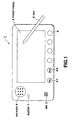
- FIG. 1 is a front view showing the exterior of a communication terminal device in accordance with the first embodiment of the present invention.
- a body 1 of the communication terminal device comprises a cabinet that is of a size to allow users to hold it in one hand.
- a liquid crystal display 3 In the center of the front side of the device body 1 is placed a liquid crystal display 3 on which is arranged a touch panel 2.
- a number of keys 4 are arranged below the liquid crystal display 3 (touch panel 2).
- the device body 1 has an antenna built in to make communication with a radio telephone base station.
- the touch panel 2 is adapted to generate a voltage signal according to a point on the touch panel 2 at which a pen 8 touches the panel.
- the X and Y coordinates on the liquid crystal display 3 that correspond to the point of touch are recognized by the voltage signal generated from the touch panel 2. Based on the result of recognition, input handwriting data is displayed and processing corresponding to the contents of display is carried out.
- the keys 4 include various mode setting keys for selectively setting built-in function modes of the communication terminal device, such as a "TEL" key 4-1 for setting a telephone function, a "FAX” key 4-2 for setting a facsimile function, a key for setting a data entry/retrieval function, etc.
- the microphone 5 and the speaker 6 are respectively used as a voice input device and a voice output device for telephone conversations when the telephone function mode is set.
- the buzzer 7 produces input confirmation beeping sounds when the keys 4 are operated or the touch panel 2 is touched with the pen.
- a dial input screen appears on the liquid crystal display 3.
- a dial signal is transmitted to a wireless telephone base station through the built-in antenna, allowing telephone communication through the microphone 5 and the speaker 6.
- a dialing signal is transmitted to a wireless telephone base station through the built-in antenna, whereby data transmission is made.
- a ringing tone is produced by the speaker 6 and the user performs a receiving operation with a key 4, he or she is allowed to have a conversation with a call originating party through the microphone 5 and the speaker 6. If, when the ringing tone is produced by the speaker 6, an incoming signal is a facsimile signal, automatic switching is made to the facsimile receive mode, allowing reception of data.
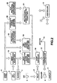
- FIG. 2 is a block diagram of an input noise cancellation circuit according to the first embodiment of the communication terminal device.
- the communication terminal device is equipped with a controller 11.
- the controller 11 controls all of operations of the communication terminal device such as the telephone function, the fax function, the data entry/retrieval function, the input noise cancellation function, etc.
- the controller 11 To the controller 11 are connected the touch panel 2, the liquid crystal display 3, the keys 4, the microphone 5, and the speaker 6. Further, to the controller 11, an antenna 13 is connected through a communication controller 12 and circuits 14 to 22 for canceling input noises are connected.
- a voice signal from the microphone 5 is modulated in the communication controller 12, then transmitted through the antenna 13.
- a voice signal received and recovered by the communication controller 12 is output from the speaker 6.
- facsimile function mode data entered by operating the touch panel 2 or the keys 4 or stored data is modulated in the communication controller 12 and transmitted through the antenna 13. Facsimile data received by the antenna 13 and demodulated by the communication controller 12 is displayed on the liquid crystal display 3.
- An input confirmation sound generator 14 causes the buzzer 7 to generate an input confirmation beeping sound, each time an input operation is performed on the touch panel 2 or an input operation based on keys 4 is performed.
- the input confirmation sound signal from the input confirmation sound generating circuit 14 is supplied to an input confirmation sound canceling signal generating circuit 15 as well as to the buzzer 7.
- the input confirmation sound canceling signal generator 15 generates an input confirmation sound canceling signal which has substantially the same level as an actual input signal from the microphone 5 (which is attenuated by a predetermined level from the level of the input confirmation sound from the buzzer 7 at the time of generation) when an input confirmation beeping sound generated by the buzzer 7 is picked up by the microphone 5.
- the input confirmation sound canceling signal generated by the input confirmation sound canceling signal generator 15 is supplied to a noise canceler 16.
- a sound signal entered by the microphone 5 is delayed by a predetermined period of time in a delay circuit 17, then supplied to the noise canceler 16.
- the input confirmation sound canceling signal generated by the input confirmation sound canceling signal generator 15 when the input confirmation beeping sound is generated becomes equal in level to a signal from the microphone 5 corresponding to the input confirmation beeping sound.
- the input confirmation sound canceling signal and the actual input confirmation sound signal from the microphone 5 are supplied to the noise canceler 16.
- a pen impact sound canceling signal generator 18 reads pen impact sound sample data stored in a pen impact sound sample data storage 19 to generate a pen impact sound canceling signal when it is supplied with a first touch location signal at the start of contact of the pen 8 with the touch panel 2.
- the pen impact sound canceling signal generated by the pen impact sound canceling signal generator 18 is supplied to the noise canceler 16.
- the pen impact sound sample data stored in the pen impact sound sample data storage 19 is obtained by sampling a pipping sound caused by the pen 8 impacting onto the touch panel 2 at the start of an operation of bringing the pen 9 into contact with the touch panel 2.
- the pen impact sound canceling signal generated by the pen impact sound canceling signal generator 18 based on the pen impact sound sample data is made equal in level to an actual input signal from the microphone 5 corresponding to a pen impact pipping sound picked up by the microphone 5.
- a pen impact sound canceling signal generated by the pen impact sound canceling signal generator 18 when the pen impact pipping sound is generated becomes equal in level to a signal for the pen impact pipping sound entered into the microphone 5.
- the pen impact sound canceling signal and the actual pen impact sound signal input by the microphone 5 are supplied to the noise canceler 16.
- a coordinate string storage/detector 20 stores X, Y coordinate data corresponding to touch locations detected at a predetermined interval when the pen 8 is in contact with the touch panel 2 and detects whether or not the rate of change of the coordinates has exceeded a preset threshold. If it is detected that the rate of change of the coordinates has exceeded the threshold, then a threshold at which a frictional crackling sound begins to occur due to movement of the pen 8 on the touch panel 2 is considered to have been exceeded. As a result, a pen frictional sound generation detection signal is supplied to a pen frictional sound canceling signal generator 21.
- a pen frictional sound canceling signal generator 21 reads pen frictional sound sample data stored in a pen frictional sound sample data storage 22 to generate a pen frictional sound canceling signal when it is supplied with the pen frictional sound generation detection signal from the coordinate string storage/detector 20.
- the pen frictional sound canceling signal generated by the pen frictional sound canceling signal generator 21 is supplied to the noise canceler 16.
- the pen frictional sound sample data stored in the pen frictional sound sample data storage 22 is obtained by sampling a frictional crackling sound, caused by friction between the pen 8 and the touch panel 2 due to movement of the pen 8 on the touch panel 2.
- the pen frictional sound canceling signal generated by the pen frictional sound canceling signal generator 21 based on the pen frictional sound sample data is made equal in level to an actual input signal from the microphone 5 corresponding to a pen frictional crackling sound picked up by the microphone 5.
- a pen frictional sound canceling signal generated by the pen frictional sound canceling signal generator 21 when a pen frictional crackling sound is generated becomes equal in level to an input signal from the microphone 5 for the pen frictional crackling sound.
- the pen frictional sound canceling signal and the actual pen frictional sound signal input by the microphone 5 are supplied to the noise canceler 16.
- the noise canceler 16 subtracts an input confirmation sound canceling signal generated by the input confirmation sound canceling signal generator 15 from a sound signal input from the microphone 5 and delayed by the delay circuit 17, the sound signal including a signal component corresponding to the input confirmation beeping sound.
- the signal component corresponding to the input confirmation beeping sound and mixed in the sound signal input from the microphone 5 is canceled.
- the noise canceler 16 subtracts a pen impact sound canceling signal generated by the pen impact sound canceling signal generator 18 from a sound signal input from the microphone 5 and delayed by the delay circuit 17, the sound signal containing a signal component corresponding to the pen impact pipping sound.
- the signal component corresponding to the pen impact pipping sound and mixed in the sound signal input from the microphone 5 is canceled.
- the noise canceler 16 subtracts a pen frictional sound canceling signal generated by the pen frictional sound canceling signal generator 21 from a sound signal input from the microphone 5 and delayed by the delay circuit 17, the sound signal containing a signal component corresponding to the pen frictional crackling sound.
- the signal component corresponding to the pen frictional crackling sound and mixed in the sound signal input from the microphone 5 is canceled.
- the voice signal from which noise components corresponding to input confirmation beeping sounds, pen impact pipping sounds, and pen frictional crackling sounds based on various input operations are canceled by the noise canceler 16 is supplied to the communication controller 12 for modulation and then transmitted from the antenna 13.
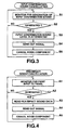
- FIG. 3 is a flowchart illustrating the input confirmation sound canceling process in the communication terminal device.
- the input confirmation sound canceling signal generator 15 monitors the input confirmation sound generator 14 for the generation of an input confirmation sound in response to an input operation by the keys 4 or the pen 8 (block S1).
- the input confirmation sound canceling signal generator 15 produces an input confirmation sound canceling signal which has a level equal to the actual microphone input level of the input confirmation sound (corresponding to the level of the input confirmation sound attenuated by a predetermined level) and outputs it to the noise canceler 16 (blocks S2, S3, and S4).
- an input confirmation sound canceling signal generated by the input confirmation sound canceling signal generator 15 is subtracted from a sound signal supplied from the microphone 5 through the delay circuit 17 and having the input confirmation beeping sound mixed in, so that a voice signal having the input confirmation beeping sound component canceled is output to the communication controller 12 and then transmitted from the antenna 13 (block S5).
- FIG. 4 is a flowchart illustrating the pen impact sound canceling process in the communication terminal device of the first embodiment.
- the pen impact sound canceling signal generator 18 monitors for the start of an input operation of bringing the pen 8 into contact with the touch panel 2 (block A1). Upon detecting a first coordinate input signal, the generator 18 considers that an impact pipping sound caused by impact of the pen 8 onto the touch panel 2 was generated and reads pen impact sound sample data from the pen impact sound sample data storage 19 (blocks A2, A3). An impact sound canceling signal which has the same level as when the pen impact pipping sound is actually input to the microphone 5 is generated and then sent to the noise canceler 16 (block A4).
- the pen impact sound canceling signal generated from the pen impact sound canceling signal generator 18 is subtracted from a sound signal supplied from the microphone 5 through the delay circuit 17 and having the pen impact pipping sound mixed in, so that a voice signal having the pen impact pipping sound component canceled is output to the communication controller 12 and then transmitted from the antenna 13 (block A5).
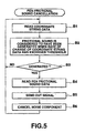
- FIG. 5 is a flowchart illustrating the pen frictional sound canceling process in the communication terminal device of the first embodiment.
- the coordinate string storage/detector 20 stores coordinate string data and monitors for the rate of change of the coordinates when the pen 8 is moved on the touch panel (blocks B1, B2). When the rate of change of the coordinates exceeds the predetermined threshold, the detector 20 determines that a frictional crackling sound caused by friction between the pen 8 and the touch panel 2 was generated and reads pen frictional sound sample data from the pen frictional sound sample data storage 22 (blocks B3, B4).
- a pen frictional sound canceling signal which has the same level as when the pen frictional crackling sound is actually input to the microphone is generated and then sent to the noise canceler 16 (block A4).
- the pen frictional sound canceling signal generated by the pen frictional sound canceling signal generator 21 is subtracted from a sound signal supplied from the microphone 5 through the delay circuit 17 and having the pen fictional crackling sound mixed in, so that a voice signal that is free from the pen frictional crackling sound component is output to the communication controller 12 and then transmitted from the antenna 13.
- a voice signal that contains noises caused by key- or pen-based input operations is not transmitted during conversation in the telephone mode and hence high-quality conversation can be maintained.
- noise canceling signals are produced, each of which is equal in level to a signal as it would be output from the microphone 5 if a corresponding noise were actually entered into the microphone 5.
- Each noise canceling signal is subtracted by the noise canceler 16 from a sound signal supplied from the microphone 5 through the delay circuit 17 and mixed with the noises, and a resulting voice signal that is free from the noise components is output to the communication controller 12 and then transmitted from the antenna 13.
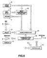
- the input noise canceling circuit according to the first embodiment of the communication terminal device is arranged to eliminate only noise components based on key- or pen-based input operations from a sound signal supplied from the microphone 5, it may be arranged as shown in FIG. 6.
- An input noise canceling circuit according to a second embodiment shown in FIG. 6 is arranged such that an input sound from the microphone is cut off or interrupted for a fixed period of time after the occurrence of a noise due to an input operation (stopping of sound input), thereby canceling noise components.
- FIG. 6 is a block diagram of the input noise canceling circuit according to the second embodiment of the communication terminal device.
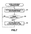
- FIG. 7 is a flowchart for the noise component canceling process of the input noise canceling circuit according to the second embodiment of the communication terminal device.
- An input confirmation sound generating signal output from an input confirmation sound generator 14 in response to a key- or pen-based input operation is supplied to the buzzer 7 and directly to a noise canceler 31. Also, a pen impact sound generating signal and a pen frictional sound generating signal based on pen-based input operations are supplied directly to the noise canceler 31.
- the noise canceler 31 monitors for a pen input or key input on the touch panel 2 (block C1). In the presence of a key input, the noise canceler 31 stops a sound signal from being input thereto from the microphone 5 through the delay circuit 15 for a predetermined period of time from the time that an input confirmation sound generating signal was output from the input confirmation sound generator 14.
- the noise canceler 31 stops a sound signal from being input thereto from the microphone 5 through the delay circuit 15 for the predetermined period of time from the time that the pen input was initiated (blocks C2, C3).
- a communication terminal device comprising means for inputting data based on manual operations; voice input means; noise canceling means for canceling noise components other than voice components from a sound signal picked up by said voice input means, said noise components being generated by manual operations of said data inputting means; and means for transmitting a sound signal which has noise components canceled by said noise canceling means.
- noise components generated in response to input operations in the pen- or key-based data inputting means are canceled from a voice signal input from the voice input means and the resulting voice signal free from noises is then transmitted.
- an input confirmation beeping sound a pen impact pipping sound caused by impact of the pen onto the touch panel, and a pen frictional crackling sound caused by friction between the pen and the touch panel are canceled, telephone conversations will not be interrupted.
Landscapes
- Engineering & Computer Science (AREA)
- Physics & Mathematics (AREA)
- Theoretical Computer Science (AREA)
- Human Computer Interaction (AREA)
- Acoustics & Sound (AREA)
- Multimedia (AREA)
- Health & Medical Sciences (AREA)
- Audiology, Speech & Language Pathology (AREA)
- General Engineering & Computer Science (AREA)
- General Physics & Mathematics (AREA)
- Signal Processing (AREA)
- Computational Linguistics (AREA)
- Quality & Reliability (AREA)
- General Health & Medical Sciences (AREA)
- Computer Hardware Design (AREA)
- Telephonic Communication Services (AREA)
- Circuits Of Receivers In General (AREA)
- Telephone Function (AREA)
Description
Claims (3)
- A communication terminal comprising:characterized in that there is provided:a touch panel (2) to input data by use of a pen (8); and/orkeys (4) of a keyboard; anda microphone (5) for inputting a sound signal, the pen or the keys producing noise which is added to the microphone input sound signal;means for detecting an input operation of either the pen (8) or the keys (4) to obtain the information on the occurrence of an expected noise signal to eliminate the noise from the microphone input sound signal,means (19, 22) for storing sample noise signals caused by the pen or the keys; andmeans (15, 18, 21) for generating a noise cancelling signal based on the sample noise signals in response of detection of the respective input operation of either the pen or the keys; andmeans (16; 31) for subtracting the respective noise cancelling signal from the sound signal provided by the microphone (5).
- A communication terminal according to claim 1, characterized in that the keyboard is adapted to produce an input confirmation sound on actuation of a key and that the means for storing sample noise signals includes a corresponding sample noise.
- A communication terminal according to claim 1 or 2 , characterized in that the means for detecting the input operation comprises means for detecting a rate of change of a position of the pen (8) on the touch panel (2) and means (20) for comparing the rate of change with a threshold level to detect the movement of the pen (8) and, if the rate of change exceeds the threshold level, to activate the respective frictional noise cancelling signal.
Applications Claiming Priority (4)
| Application Number | Priority Date | Filing Date | Title |
|---|---|---|---|
| JP306059/95 | 1995-11-24 | ||
| JP7306059A JPH09149157A (en) | 1995-11-24 | 1995-11-24 | Communication terminal device |
| JP30605995 | 1995-11-24 | ||
| PCT/JP1996/003430 WO1997019401A1 (en) | 1995-11-24 | 1996-11-22 | Communication terminal device |
Publications (2)
| Publication Number | Publication Date |
|---|---|
| EP0807286A1 EP0807286A1 (en) | 1997-11-19 |
| EP0807286B1 true EP0807286B1 (en) | 2004-02-25 |
Family
ID=17952559
Family Applications (1)
| Application Number | Title | Priority Date | Filing Date |
|---|---|---|---|
| EP96938527A Expired - Lifetime EP0807286B1 (en) | 1995-11-24 | 1996-11-22 | Communication terminal device |
Country Status (7)
| Country | Link |
|---|---|
| US (1) | US5930372A (en) |
| EP (1) | EP0807286B1 (en) |
| JP (1) | JPH09149157A (en) |
| KR (1) | KR100283880B1 (en) |
| AU (1) | AU7589696A (en) |
| DE (1) | DE69631644T2 (en) |
| WO (1) | WO1997019401A1 (en) |
Families Citing this family (23)
| Publication number | Priority date | Publication date | Assignee | Title |
|---|---|---|---|---|
| JPH11103263A (en) * | 1997-09-26 | 1999-04-13 | Dowa Mining Co Ltd | Communication equipment/measuring instrument provided with simple input device |
| KR100810218B1 (en) * | 1999-03-18 | 2008-03-06 | 삼성전자주식회사 | Apparatus and method for touch screen panel data input by a user through a touch screen panel in a digital portable terminal |
| GB9928682D0 (en) * | 1999-12-06 | 2000-02-02 | Electrotextiles Comp Ltd | Input apparatus and a method of generating control signals |
| EP1109379A1 (en) * | 1999-12-16 | 2001-06-20 | Ascom AG | Method and telephone terminal for optimizing a wanted signal |
| JP2003295899A (en) * | 2002-03-28 | 2003-10-15 | Fujitsu Ltd | Voice input device |
| WO2005045807A1 (en) * | 2003-11-05 | 2005-05-19 | Sanyo Electric Co., Ltd. | Electronic device |
| JP4876378B2 (en) * | 2004-08-27 | 2012-02-15 | 日本電気株式会社 | Audio processing apparatus, audio processing method, and audio processing program |
| JP5182556B2 (en) * | 2005-10-26 | 2013-04-17 | 日本電気株式会社 | Telephone terminal and signal processing method |
| US20070160223A1 (en) * | 2006-01-03 | 2007-07-12 | Cusack Francis J Jr | Method and apparatus for noise canceling headphones |
| KR101340200B1 (en) * | 2007-05-06 | 2013-12-10 | 주식회사 엘지씨엔에스 | Apparatus and method for providing information using a tablet monitor |
| GB0919672D0 (en) * | 2009-11-10 | 2009-12-23 | Skype Ltd | Noise suppression |
| US8411874B2 (en) * | 2010-06-30 | 2013-04-02 | Google Inc. | Removing noise from audio |
| US20130089219A1 (en) * | 2011-10-05 | 2013-04-11 | Research In Motion Limited | Noise reduction in an electronic device |
| US20130343555A1 (en) * | 2011-12-22 | 2013-12-26 | Uri Yehuday | System and Apparatuses that remove clicks for Game controllers and keyboards |
| US20130287217A1 (en) * | 2012-04-27 | 2013-10-31 | Research In Motion Corporation | Noise handling during audio and video recording |
| JP6136218B2 (en) * | 2012-12-03 | 2017-05-31 | 富士通株式会社 | Sound processing apparatus, method, and program |
| US8867757B1 (en) * | 2013-06-28 | 2014-10-21 | Google Inc. | Microphone under keyboard to assist in noise cancellation |
| JP6586907B2 (en) * | 2016-03-07 | 2019-10-09 | 株式会社リコー | Information processing apparatus, conference system, and control method for information processing apparatus |
| US10365763B2 (en) * | 2016-04-13 | 2019-07-30 | Microsoft Technology Licensing, Llc | Selective attenuation of sound for display devices |
| GB2551724B (en) * | 2016-06-27 | 2022-04-06 | Pambry Electronics Ltd | Sound exposure meter |
| US10283135B2 (en) * | 2016-12-22 | 2019-05-07 | Microsoft Technology Licensing, Llc | Touchscreen tapping noise suppression |
| US10803857B2 (en) * | 2017-03-10 | 2020-10-13 | James Jordan Rosenberg | System and method for relative enhancement of vocal utterances in an acoustically cluttered environment |
| CN111813243A (en) * | 2019-04-11 | 2020-10-23 | 群光电子股份有限公司 | Mouse device and noise canceling method thereof |
Family Cites Families (3)
| Publication number | Priority date | Publication date | Assignee | Title |
|---|---|---|---|---|
| KR100189961B1 (en) * | 1992-04-09 | 1999-06-01 | 윤종용 | Noise elimination apparatus |
| CA2115210C (en) * | 1993-04-21 | 1997-09-23 | Joseph C. Andreshak | Interactive computer system recognizing spoken commands |
| JPH06314162A (en) * | 1993-04-29 | 1994-11-08 | Internatl Business Mach Corp <Ibm> | Multimedia stylus |
-
1995
- 1995-11-24 JP JP7306059A patent/JPH09149157A/en active Pending
-
1996
- 1996-11-22 WO PCT/JP1996/003430 patent/WO1997019401A1/en not_active Ceased
- 1996-11-22 DE DE69631644T patent/DE69631644T2/en not_active Expired - Lifetime
- 1996-11-22 KR KR1019970705042A patent/KR100283880B1/en not_active Expired - Fee Related
- 1996-11-22 AU AU75896/96A patent/AU7589696A/en not_active Abandoned
- 1996-11-22 EP EP96938527A patent/EP0807286B1/en not_active Expired - Lifetime
- 1996-11-22 US US08/875,804 patent/US5930372A/en not_active Expired - Lifetime
Also Published As
| Publication number | Publication date |
|---|---|
| DE69631644D1 (en) | 2004-04-01 |
| US5930372A (en) | 1999-07-27 |
| DE69631644T2 (en) | 2004-08-05 |
| EP0807286A1 (en) | 1997-11-19 |
| JPH09149157A (en) | 1997-06-06 |
| KR100283880B1 (en) | 2001-03-02 |
| WO1997019401A1 (en) | 1997-05-29 |
| AU7589696A (en) | 1997-06-11 |
| KR19980701648A (en) | 1998-06-25 |
Similar Documents
| Publication | Publication Date | Title |
|---|---|---|
| EP0807286B1 (en) | Communication terminal device | |
| US6518957B1 (en) | Communications device with touch sensitive screen | |
| US5933783A (en) | Portable terminal | |
| AU704945B2 (en) | Communications apparatus | |
| US20080129703A1 (en) | Portable terminal device and control method thereof | |
| US5526405A (en) | Cordless telephone apparatus with a speakerphone operation mode cordless | |
| JP3327326B2 (en) | Mobile phone malfunction prevention method and malfunction prevention circuit | |
| KR20050120390A (en) | Speaker phone control apparatus and method for mobile station using proximity sensor | |
| US6055309A (en) | Circuit and method for automatically cutting off a speech path and converting to a standby state upon completion of speakerphone speech in a cordless telephone | |
| JP2000312255A (en) | Intercom equipment | |
| JP3296685B2 (en) | Mobile phone equipment | |
| KR20030022556A (en) | Method for automatically locking touch screen of personal digital assistant | |
| JP3354347B2 (en) | Mobile phone equipment | |
| KR100233724B1 (en) | Method for setting option of facsimile by potable device combined with cordless telephone | |
| KR100186712B1 (en) | Receiver display in telephone and its method | |
| KR100227491B1 (en) | Dial number memorable telephone | |
| JP2962261B2 (en) | Mobile phone | |
| KR100218692B1 (en) | Telephone having automatic on/off switching function in a hook switch | |
| KR101394278B1 (en) | Method for executing communication mode in mobile terminal | |
| JPH06177946A (en) | Cordless telephone set | |
| JPH05327833A (en) | Cordless telephone set | |
| JPH10136068A (en) | Wireless communication handset | |
| KR19980013694A (en) | A pen-writing function with telephone | |
| JPH0654039A (en) | Telephone set | |
| KR20000063831A (en) | Internet phone/telephone/sound card/e-mail alarm system using serial connection between computer and telephone |
Legal Events
| Date | Code | Title | Description |
|---|---|---|---|
| PUAI | Public reference made under article 153(3) epc to a published international application that has entered the european phase |
Free format text: ORIGINAL CODE: 0009012 |
|
| 17P | Request for examination filed |
Effective date: 19970814 |
|
| AK | Designated contracting states |
Kind code of ref document: A1 Designated state(s): CH DE ES FI FR GB IT LI NL SE |
|
| RAP1 | Party data changed (applicant data changed or rights of an application transferred) |
Owner name: CASIO COMPUTER CO., LTD. |
|
| 17Q | First examination report despatched |
Effective date: 20021106 |
|
| GRAP | Despatch of communication of intention to grant a patent |
Free format text: ORIGINAL CODE: EPIDOSNIGR1 |
|
| GRAS | Grant fee paid |
Free format text: ORIGINAL CODE: EPIDOSNIGR3 |
|
| GRAA | (expected) grant |
Free format text: ORIGINAL CODE: 0009210 |
|
| RIC1 | Information provided on ipc code assigned before grant |
Ipc: 7G 06F 3/16 A |
|
| AK | Designated contracting states |
Kind code of ref document: B1 Designated state(s): CH DE ES FI FR GB IT LI NL SE |
|
| PG25 | Lapsed in a contracting state [announced via postgrant information from national office to epo] |
Ref country code: NL Free format text: LAPSE BECAUSE OF FAILURE TO SUBMIT A TRANSLATION OF THE DESCRIPTION OR TO PAY THE FEE WITHIN THE PRESCRIBED TIME-LIMIT Effective date: 20040225 Ref country code: LI Free format text: LAPSE BECAUSE OF FAILURE TO SUBMIT A TRANSLATION OF THE DESCRIPTION OR TO PAY THE FEE WITHIN THE PRESCRIBED TIME-LIMIT Effective date: 20040225 Ref country code: IT Free format text: LAPSE BECAUSE OF FAILURE TO SUBMIT A TRANSLATION OF THE DESCRIPTION OR TO PAY THE FEE WITHIN THE PRESCRIBED TIME-LIMIT;WARNING: LAPSES OF ITALIAN PATENTS WITH EFFECTIVE DATE BEFORE 2007 MAY HAVE OCCURRED AT ANY TIME BEFORE 2007. THE CORRECT EFFECTIVE DATE MAY BE DIFFERENT FROM THE ONE RECORDED. Effective date: 20040225 Ref country code: CH Free format text: LAPSE BECAUSE OF FAILURE TO SUBMIT A TRANSLATION OF THE DESCRIPTION OR TO PAY THE FEE WITHIN THE PRESCRIBED TIME-LIMIT Effective date: 20040225 |
|
| REG | Reference to a national code |
Ref country code: GB Ref legal event code: FG4D |
|
| REG | Reference to a national code |
Ref country code: CH Ref legal event code: EP |
|
| REF | Corresponds to: |
Ref document number: 69631644 Country of ref document: DE Date of ref document: 20040401 Kind code of ref document: P |
|
| PG25 | Lapsed in a contracting state [announced via postgrant information from national office to epo] |
Ref country code: SE Free format text: LAPSE BECAUSE OF FAILURE TO SUBMIT A TRANSLATION OF THE DESCRIPTION OR TO PAY THE FEE WITHIN THE PRESCRIBED TIME-LIMIT Effective date: 20040525 |
|
| PG25 | Lapsed in a contracting state [announced via postgrant information from national office to epo] |
Ref country code: ES Free format text: LAPSE BECAUSE OF FAILURE TO SUBMIT A TRANSLATION OF THE DESCRIPTION OR TO PAY THE FEE WITHIN THE PRESCRIBED TIME-LIMIT Effective date: 20040605 |
|
| NLV1 | Nl: lapsed or annulled due to failure to fulfill the requirements of art. 29p and 29m of the patents act | ||
| REG | Reference to a national code |
Ref country code: CH Ref legal event code: PL |
|
| ET | Fr: translation filed | ||
| PLBE | No opposition filed within time limit |
Free format text: ORIGINAL CODE: 0009261 |
|
| STAA | Information on the status of an ep patent application or granted ep patent |
Free format text: STATUS: NO OPPOSITION FILED WITHIN TIME LIMIT |
|
| 26N | No opposition filed |
Effective date: 20041126 |
|
| PGFP | Annual fee paid to national office [announced via postgrant information from national office to epo] |
Ref country code: FR Payment date: 20131120 Year of fee payment: 18 Ref country code: DE Payment date: 20131121 Year of fee payment: 18 Ref country code: GB Payment date: 20131120 Year of fee payment: 18 |
|
| PGFP | Annual fee paid to national office [announced via postgrant information from national office to epo] |
Ref country code: FI Payment date: 20131113 Year of fee payment: 18 |
|
| REG | Reference to a national code |
Ref country code: DE Ref legal event code: R119 Ref document number: 69631644 Country of ref document: DE |
|
| GBPC | Gb: european patent ceased through non-payment of renewal fee |
Effective date: 20141122 |
|
| PG25 | Lapsed in a contracting state [announced via postgrant information from national office to epo] |
Ref country code: FI Free format text: LAPSE BECAUSE OF NON-PAYMENT OF DUE FEES Effective date: 20141122 |
|
| REG | Reference to a national code |
Ref country code: FR Ref legal event code: ST Effective date: 20150731 |
|
| PG25 | Lapsed in a contracting state [announced via postgrant information from national office to epo] |
Ref country code: DE Free format text: LAPSE BECAUSE OF NON-PAYMENT OF DUE FEES Effective date: 20150602 Ref country code: GB Free format text: LAPSE BECAUSE OF NON-PAYMENT OF DUE FEES Effective date: 20141122 |
|
| PG25 | Lapsed in a contracting state [announced via postgrant information from national office to epo] |
Ref country code: FR Free format text: LAPSE BECAUSE OF NON-PAYMENT OF DUE FEES Effective date: 20141201 |