EP0807024B2 - Coating methods and compositions for production of digitized stereoscopic polarizing images - Google Patents
Coating methods and compositions for production of digitized stereoscopic polarizing images Download PDFInfo
- Publication number
- EP0807024B2 EP0807024B2 EP96903684A EP96903684A EP0807024B2 EP 0807024 B2 EP0807024 B2 EP 0807024B2 EP 96903684 A EP96903684 A EP 96903684A EP 96903684 A EP96903684 A EP 96903684A EP 0807024 B2 EP0807024 B2 EP 0807024B2
- Authority
- EP
- European Patent Office
- Prior art keywords
- ink
- image
- coating
- substrate
- polarizing
- Prior art date
- Legal status (The legal status is an assumption and is not a legal conclusion. Google has not performed a legal analysis and makes no representation as to the accuracy of the status listed.)
- Expired - Lifetime
Links
Images


Classifications
-
- B—PERFORMING OPERATIONS; TRANSPORTING
- B41—PRINTING; LINING MACHINES; TYPEWRITERS; STAMPS
- B41M—PRINTING, DUPLICATING, MARKING, OR COPYING PROCESSES; COLOUR PRINTING
- B41M5/00—Duplicating or marking methods; Sheet materials for use therein
- B41M5/50—Recording sheets characterised by the coating used to improve ink, dye or pigment receptivity, e.g. for ink-jet or thermal dye transfer recording
- B41M5/52—Macromolecular coatings
-
- B—PERFORMING OPERATIONS; TRANSPORTING
- B41—PRINTING; LINING MACHINES; TYPEWRITERS; STAMPS
- B41J—TYPEWRITERS; SELECTIVE PRINTING MECHANISMS, i.e. MECHANISMS PRINTING OTHERWISE THAN FROM A FORME; CORRECTION OF TYPOGRAPHICAL ERRORS
- B41J11/00—Devices or arrangements of selective printing mechanisms, e.g. ink-jet printers or thermal printers, for supporting or handling copy material in sheet or web form
- B41J11/0015—Devices or arrangements of selective printing mechanisms, e.g. ink-jet printers or thermal printers, for supporting or handling copy material in sheet or web form for treating before, during or after printing or for uniform coating or laminating the copy material before or after printing
-
- B—PERFORMING OPERATIONS; TRANSPORTING
- B41—PRINTING; LINING MACHINES; TYPEWRITERS; STAMPS
- B41J—TYPEWRITERS; SELECTIVE PRINTING MECHANISMS, i.e. MECHANISMS PRINTING OTHERWISE THAN FROM A FORME; CORRECTION OF TYPOGRAPHICAL ERRORS
- B41J11/00—Devices or arrangements of selective printing mechanisms, e.g. ink-jet printers or thermal printers, for supporting or handling copy material in sheet or web form
- B41J11/004—Platenless printing, i.e. conveying the printing material freely, without support on its back, through the printing zone opposite to the print head
-
- B—PERFORMING OPERATIONS; TRANSPORTING
- B41—PRINTING; LINING MACHINES; TYPEWRITERS; STAMPS
- B41J—TYPEWRITERS; SELECTIVE PRINTING MECHANISMS, i.e. MECHANISMS PRINTING OTHERWISE THAN FROM A FORME; CORRECTION OF TYPOGRAPHICAL ERRORS
- B41J2/00—Typewriters or selective printing mechanisms characterised by the printing or marking process for which they are designed
- B41J2/005—Typewriters or selective printing mechanisms characterised by the printing or marking process for which they are designed characterised by bringing liquid or particles selectively into contact with a printing material
- B41J2/01—Ink jet
- B41J2/21—Ink jet for multi-colour printing
- B41J2/2107—Ink jet for multi-colour printing characterised by the ink properties
-
- B—PERFORMING OPERATIONS; TRANSPORTING
- B41—PRINTING; LINING MACHINES; TYPEWRITERS; STAMPS
- B41J—TYPEWRITERS; SELECTIVE PRINTING MECHANISMS, i.e. MECHANISMS PRINTING OTHERWISE THAN FROM A FORME; CORRECTION OF TYPOGRAPHICAL ERRORS
- B41J3/00—Typewriters or selective printing or marking mechanisms characterised by the purpose for which they are constructed
- B41J3/60—Typewriters or selective printing or marking mechanisms characterised by the purpose for which they are constructed for printing on both faces of the printing material
-
- B—PERFORMING OPERATIONS; TRANSPORTING
- B41—PRINTING; LINING MACHINES; TYPEWRITERS; STAMPS
- B41M—PRINTING, DUPLICATING, MARKING, OR COPYING PROCESSES; COLOUR PRINTING
- B41M3/00—Printing processes to produce particular kinds of printed work, e.g. patterns
- B41M3/06—Veined printings; Fluorescent printings; Stereoscopic images; Imitated patterns, e.g. tissues, textiles
-
- C—CHEMISTRY; METALLURGY
- C09—DYES; PAINTS; POLISHES; NATURAL RESINS; ADHESIVES; COMPOSITIONS NOT OTHERWISE PROVIDED FOR; APPLICATIONS OF MATERIALS NOT OTHERWISE PROVIDED FOR
- C09D—COATING COMPOSITIONS, e.g. PAINTS, VARNISHES OR LACQUERS; FILLING PASTES; CHEMICAL PAINT OR INK REMOVERS; INKS; CORRECTING FLUIDS; WOODSTAINS; PASTES OR SOLIDS FOR COLOURING OR PRINTING; USE OF MATERIALS THEREFOR
- C09D11/00—Inks
- C09D11/30—Inkjet printing inks
- C09D11/32—Inkjet printing inks characterised by colouring agents
- C09D11/328—Inkjet printing inks characterised by colouring agents characterised by dyes
-
- G—PHYSICS
- G06—COMPUTING OR CALCULATING; COUNTING
- G06K—GRAPHICAL DATA READING; PRESENTATION OF DATA; RECORD CARRIERS; HANDLING RECORD CARRIERS
- G06K15/00—Arrangements for producing a permanent visual presentation of the output data, e.g. computer output printers
-
- B—PERFORMING OPERATIONS; TRANSPORTING
- B41—PRINTING; LINING MACHINES; TYPEWRITERS; STAMPS
- B41M—PRINTING, DUPLICATING, MARKING, OR COPYING PROCESSES; COLOUR PRINTING
- B41M5/00—Duplicating or marking methods; Sheet materials for use therein
- B41M5/50—Recording sheets characterised by the coating used to improve ink, dye or pigment receptivity, e.g. for ink-jet or thermal dye transfer recording
- B41M5/502—Recording sheets characterised by the coating used to improve ink, dye or pigment receptivity, e.g. for ink-jet or thermal dye transfer recording characterised by structural details, e.g. multilayer materials
- B41M5/508—Supports
-
- B—PERFORMING OPERATIONS; TRANSPORTING
- B41—PRINTING; LINING MACHINES; TYPEWRITERS; STAMPS
- B41M—PRINTING, DUPLICATING, MARKING, OR COPYING PROCESSES; COLOUR PRINTING
- B41M5/00—Duplicating or marking methods; Sheet materials for use therein
- B41M5/50—Recording sheets characterised by the coating used to improve ink, dye or pigment receptivity, e.g. for ink-jet or thermal dye transfer recording
- B41M5/52—Macromolecular coatings
- B41M5/5227—Macromolecular coatings characterised by organic non-macromolecular additives, e.g. UV-absorbers, plasticisers, surfactants
-
- B—PERFORMING OPERATIONS; TRANSPORTING
- B41—PRINTING; LINING MACHINES; TYPEWRITERS; STAMPS
- B41M—PRINTING, DUPLICATING, MARKING, OR COPYING PROCESSES; COLOUR PRINTING
- B41M5/00—Duplicating or marking methods; Sheet materials for use therein
- B41M5/50—Recording sheets characterised by the coating used to improve ink, dye or pigment receptivity, e.g. for ink-jet or thermal dye transfer recording
- B41M5/52—Macromolecular coatings
- B41M5/5236—Macromolecular coatings characterised by the use of natural gums, of proteins, e.g. gelatins, or of macromolecular carbohydrates, e.g. cellulose
-
- B—PERFORMING OPERATIONS; TRANSPORTING
- B41—PRINTING; LINING MACHINES; TYPEWRITERS; STAMPS
- B41M—PRINTING, DUPLICATING, MARKING, OR COPYING PROCESSES; COLOUR PRINTING
- B41M7/00—After-treatment of prints, e.g. heating, irradiating, setting of the ink, protection of the printed stock
- B41M7/0027—After-treatment of prints, e.g. heating, irradiating, setting of the ink, protection of the printed stock using protective coatings or layers by lamination or by fusion of the coatings or layers
Definitions
- This invention relates to improved methods and apparatus for the production of digitized stereoscopic polarizing images.
- Ordinary (unpolarized) light is made of electromagnetic waves vibrating equally in all directions perpendicular to their direction of travel.
- Absorption-polarizing sheets polarize these light waves by partially or wholly absorbing the vectorial components vibrating in a specified direction transverse to the direction of travel.
- a stereoscopic image based on the polarization of light is generally formed of a pair of polarizing images, each of which presents a light-polarizing design or image that selectively transmits light of a predetermined vector of polarization.
- Stereoscopic image pairs having a left-eye light-polarizing image superimposed on a right-eye light-polarizing image, enable the perception of a three-dimensional image when the image pair is viewed through a pair of polarizing filters, or analyzers, oriented to allow the left-eye polarized image to reach the left eye and the right-eye polarized image to reach the right eye.
- a polarizing image can be made by a sheet that polarizes light to different percentages, depending upon the density of the image at each point. In particular, the percentage of polarization is directly related to the image's density, nearly all light being polarized in high-density areas and only a small amount of light being polarized in low-density areas.
- the most effective arrangement occurs when the polarization axis of the left-eye image is at right angles to the polarization axis of the right-eye image, and when the two layers are superimposed in such position with respect to each other that the images carried thereby are stereoscopically registered.
- a light-polarizing sheet may initially be formed by a light polarizing material, such as an optically oriented suspension of minute crystals of herapathite or other polarizing material, in a suitable medium, such as cellulose acetate.
- a picture may then be reproduced on the light polarizing sheet by altering the polarizing characteristics of the sheet over pre-determined areas of the sheet, forming the negative of the desired image.
- the areas forming the design may be protected with a coating, such as wax, and the sheet subjected to a treatment that destroys or otherwise alters the polarizing characteristics of the exposed areas.
- An alternative method for forming the stereoscopic print, as described in Land, U.S. Patent No. 2,281,101, is to employ a VectographTM sheet material comprising a linear hydrophilic polymer, such as polyvinyl alcohol (hereinafter "PVA"), which has been treated such that its molecules are substantially oriented to_be parallel to a specific axis.
- PVA polyvinyl alcohol
- Orientation of polyvinyl alcohol generally can be accomplished by softening the PVA sheet, as for example by subjecting it to heat, or to the action of a softening agent, until the sheet may be stretched or extended, and then by stretching or extending until suitable orientation of the molecules has been obtained.
- the sheet would generally be extended from two to four or five times its length. Once stretched, the PVA sheet is ready for lamination to a non-depolarizing base.
- polarizing images may be formed in PVA by printing thereon with certain dichroic, water-soluble, direct dyes of the azo type, or by staining the sheet with iodine in the presence of an iodide.
- the color of the dichroic image reproduced in this sheet may be controlled by selecting suitable dyes, stains or the like.
- the stain or dye is applied to the sheet from a halftone plate or a gelatin relief.
- dichroism is used herein as meaning the property of differential absorption of the components of polarization of an incident beam of light, depending upon the vibration directions of the components.
- Dichroic dye or stain refers to a dye or stain whose molecules possess the property of becoming linearly disposed within the oriented sheet material. For example, when a molecularly-oriented polymeric sheet is dyed with a dichroic dye, the sheet will appear dichroic, i.e., it will absorb differently the vectorial components of polarization of an incident beam of light.
- polarizing images in full color may be produced.
- the use of three subtractive dichroic dyes -- a minus Red, a minus Green, and a minus Blue dye forming respectively the Cyan, Magenta, and Yellow images -- allows the production of a full color image.
- the Land 714 patent teaches that six well-registered gelatin relief images, a cyan pair, a magenta pair, and a yellow pair, must first be prepared; one relief for each color component in each of the two directions of polarization. Each of the six gelatin reliefs is then appropriately dyed, and an image from each relief is subsequently transferred to the appropriately oriented PVA layer.
- Masking is a term used to describe various methods for enhancing separation records, or original transparencies, in order to compensate for the unwanted absorptions of the subtractive dyes used in making a full color stereoscopic image.
- Conventional photographic negatives and positives are held in register with the original slide or the separations to provide improved highlights, cleaner colors, controlled contrast, improved shadow detail, and ultimately remove unwanted colors. These methods are described in great detail in "The Reproduction Of Colour” by R.W.G. Hunt and “Neblette's Handbook Of Photography and Reprography” edited by John M. Sturge.
- EP-A-0587164 discloses the steps of spraying the print medium with a polymeric solution to form a coating over the print medium, and then applying an ink composition containing a pigment, a water soluble resin, and water, to the coating overlying the print medium.
- the polymeric solution, applied to the print medium prior to the inking step, can have an electrical charge that opposes the electrical charge of the resin contained within the ink composition.
- the ink composition in cooperation with the polymer solution applied to the print medium allegedly causes the ink to immediately aggregate.
- EP-A-04444950 discloses a system for applying a non-cellulosic compound as a coating agent to transparencies in order to permit improved toner and ink flow in the imaged areas of the transparency.
- the coatings used have a thickness ranging from 2-25 micrometers, preferably 3-10 micrometers. These coatings are understood to enable the dye to bind to the coating.
- JP-A-6191084 discloses a system having a central processing unit for preventing contamination in a body apparatus and a decrease in life of a cleaner due to adhesion of the toner to a photo sensitive member at the time of altering a pixel density in a controll ed image.
- US Patent No. 2,544,659 discloses inks containing dichroic dyes, water and wetting agents and being applied to surfaces by e.g. spraying or flowing.
- US Patent No. 5,106,417 discloses inks for use in ink jet printing.
- an object of the invention is to provide an easier and more efficient method of producing full-color stereoscopic polarizing images having clearer and crisper images, and reduced ghosting artifacts.
- Further objects of the invention include providing a coating to be used in producing digitized stereoscopic polarizing images by ink-jet printing, and formulating dichroic inks for ink-jet printing.
- One object of the invention accordingly includes providing a system that efficiently and inexpensively reduces ghost images in a stereoscopic image.
- the coating of the present invention comprises a polymeric component that is permeable to dye molecules.
- the coating can, optionally, also include a second component that serves to retard lateral diffusion of the dye during imbibition.
- the polymeric component can be, for example, a natural gum or a synthetic polymer, and the lateral diffusion-limiting component can be a discontinuous particulate filler, such as silica.
- the coatings can be permanent or temporary layers.
- the coating can be removed following imbibition of the dye to the substrate.
- the coating is permanent and includes a transparent, scratch resistant top surface and can also include UV blockers to protect the underlying image colors.
- ink-jet printers Prior to this invention, the use of ink-jet printers to apply ink to the surface of polyvinyl alcohol was often unsatisfactory. Without a coating, ink applied with the ink-jet printers typically smeared and smudged across the substrate, thus resulting in images lacking clarity and spatial precision. With a coating, as disclosed herein, the transfer of ink to a substrate and the imbibition of ink by the substrate can be regulated and controlled, thus ensuring a clear and accurate image.
- Inking methods and compositions are also disclosed herein for creating images on molecularly oriented substrates, especially on stretched and oriented polymeric sheets useful, for example, in construction of polarizing images and the like.
- the present invention is particularly adapted for use in creating polarizing images with ink jet printing devices.
- the ink compositions of the present invention as defined in claim 26 are formulated to permit rapid start-up and avoid drying in a printing head, provide smooth transfer during the jet spraying operations, and also exhibit controlled drying on the medium.
- the ink solution includes a desalted dichroic dye, deionized water, and a polyhydric alcohol in appropriate proportions to ensure flowability and controlled drying.
- a desalted dichroic dye is deionized water
- a polyhydric alcohol in appropriate proportions to ensure flowability and controlled drying.
- One preferred polyhydric alcohol is diethylene glycol.
- the ink composition further includes one or more additives selected from complexing agents, preservatives, humectants, and detergents.
- the systems described herein provide for stereoscopic images having reduced ghosting.
- the invention accomplishes these objects of the invention by forming images on first and second polarizing sheets with an ink jet printer, and by stereoscopically aligning the imprinted second polarizing sheet with the first polarizing sheet so that the image on the second polarizing sheet reduces ghost images produced by the first polarizing sheet.
- the invention forms and applies to the second polarizing sheet an image consisting of a negative of the first image superimposed with a second image, such that when the first and second polarizing sheet are aligned the ghost image is substantially reduced by the negative of the first image.
- the methods involved in this invention utilize digital technology to quickly and easily form stereoscopic images having reduced ghosting artifacts.
- This invention provides for a system that allows individuals without any particular expertise to easily manufacture improved digitized stereoscopic images having substantially no ghost images.
- FIGS. 1 through 9 wherein like reference numerals refer to like parts, there are illustrated various forms of polarizing sheets, light-polarizing images; and digitized stereoscopic polarizing images.
- FIG. 1 illustrates an imaging system 29 for producing digitized stereoscopic polarizing images, comprising an input stage 34, a digital storage device 40, a data processor 43, an ink-dispenser 24, a coater 48, and a finishing module 46.
- Input stage 34 can include an analog image module 30, a digitizing scanner 31, a digital image module 33, an image synthesis module 35, an analog-to-digital converter 36, and a multiplexer 39.
- Input block 34 is coupled to memory element 40 and supplies memory element 40 with digitized data used for creating a stereoscopic pair.
- input block 34 supplies two digitized data files for each picture in question, one representing the right-eye image and the other representing the left-eye image of a stereoscopic pair.
- Input stage 34 can accommodate multiple paths for creating digital stereoscopic imaging data, including, but not limited to: an analog image input path; a digitizing scanner input path; a digital image input path; and an image synthesis path.
- an analog image module 30 supplies an electronic analog signal representing a normal flat image for conversion to digital data by module 36.
- image module 30 can be a standard video camera.
- analog image module 30 supplies two images, one representing a left-eye image and the other representing the right-eye image. Left-eye and right-eye images can be generated through stereoscopic cameras designed for this purpose and known in the prior art.
- analog-to-digital converter 36 receives a stream of analog data from module 30 and changes the analog data to digital data.
- Converter 36 outputs to multiplexer 39 digital data representative of the analog data output by module 30.
- digitizing scanner 31 In the digitizing scanner input path, digitizing scanner 31 generates digital signals representing the flat representations of images, including photographs, slides, and the like. Preferably, digitizing scanner 31 is supplied with two images, one representing a left-eye image and the other representing the right-eye image, for which it generates two separate digital signals. Digitizing scanner 31 can be for example, a Hewlett Packard ScanJetTM Scanner produced by the Hewlett-Packard Corporation of Palo Alto, California. Digitizing scanner 31 outputs, in digital format, a representation of the subject images to multiplexer 39.
- digital image module 33 supplies a directly digitized image for conversion to a light polarizing image.
- Digital input module 33 may comprise, for example, a digital camera.
- digital image module 33 may include a digital storage device, such as a CD ROM, or floppy disc containing a digital data file corresponding to an image.
- a pair of planar images that are right-eye and left-eye views may be produced in an image synthesis module 35 from seismic rotation cameras and CAD or CAM drawing programs.
- Multiplexer, or selector, 39 connects either the signal generated by converter 36, digitizing scanner 31, digital image module 33, or image synthesis module 35 to digital memory 40.
- system 29 can exclude selector 39 and instead couple directly to digital memory 40 either converter 36, scanner 31, or digital image module 33.
- Digital memory 40 comprises a standard device for storing and retrieving digital signals, such as CD ROM, disc drives, tapes, magnetic memory devices, or random access memory. Digital memory 40 thus stores for later use data representing either a single image or a pair of left-eye and right-eye images for conversion into a stereoscopic pair of polarizing images.
- Digital memory 40 is coupled to data processing apparatus 43.
- Data processing apparatus 43 includes an element for controlling ink-dispenser 24 and an element for processing digital data supplied by memory element 40.
- Data processor 43 can include, for example, electronic apparatus capable of manipulating the data obtained from memory element 40 such that the image represented by the data can be flipped horizontally or vertically. The ability to flip the image represented by the data facilitates the stereoscopic registration of left-eye and right-eye images.
- Data processor 43 can also include electronic apparatus that allows the data representing an image's pixel density to be manipulated in a manner that allows resizing compression or expansion of the image.
- data processing apparatus 43 also contains structures for touching up the image and for enhancing the clarity or contrast of the image.
- the image clarity can be enhanced by modifying the brightness, intensity, or hue characteristics of particular pixels in the image.
- One enhancement technique involves combining the image with its mathematical derivative. The derivative of the image enhances the clarity of edges in the image.
- data processor 43 can also be used to modify the content of images, i.e., to produce composite images or collages or to remove unwanted elements.
- data processor 43 can be a general purpose computer running Adobe PhotoshopTM software produced by the Adobe Corporation of Arizona.
- digital memory 40 contains data representing both the left-eye and right-eye images of a picture being converted to a digitized stereoscopic image.
- digital memory 40 contains a three-dimensional data set describing the three-dimensional geometry of an object or of a scene: a computer graphic model.
- Image-processing apparatus 43 is used to render left and right members of a stereoscopic pair of images of the object or scene with computer graphic techniques well known in the art.
- stereoscopic image pairs can be produced from the data generated by image synthesis module 35 by rendering a model once and then rendering again after a small angular rotation around the vertical axis running through the model, or, in the case of a scene, rendering an image and then, after a small displacement in the horizontal position of the viewpoint, making a second rendering.
- Such computer graphic techniques produce with computer graphic modeling and rendering the equivalent left and right perspectives produced by stereoscopic image capture.
- Data processing apparatus 43 generally reduces or increases the pixel density of the digitized images stored in memory element 40 to a pixel density appropriate to the desired percentage of polarization.
- a digitized image may contain approximately 2000 pixels per 2.540 cm. (2000 pixels per inch) while a desirable density for the light-polarizing image is around 300 pixels per 2.540 cm. (300 pixels per inch).
- data processor 43 can reduce the pixel density by replacing a group of two or more adjacent pixels with a single new pixel representing a weighted average of the characteristics of the replaced group of adjacent pixels.
- processor 43 can increase pixel density by adding new pixels to the image between already existing pixels. The characteristics of the newly generated pixels are determined by interpolation between adjacent pixels already in the image.
- Data processing apparatus 43 is electronically coupled to ink-dispenser 24.
- Ink-dispenser 24 can include various ink-jet printers known in the art, and other printers capable of spraying ink Generally all functions of ink-dispenser 24 are slaved to control signals generated by data processor 43, except for the quantity of ink sprayed for each dot of ink.
- Ink-dispenser 24 applies, under the control of processor 43, the left-eye image to a first polarizing layer and the right-eye image to a second polarizing layer.
- the first and second sheets with left-eye and right-eye images, respectively, become light-polarizing images.
- ink-dispenser 24 applies left-eye and right-eye images to polarized layers on opposite sides of a single sheet 2, as described more fully by FIG. 5.
- the sheet described by FIG. 5 can have stretched and oriented PVA laminated to both sides of a non-depolarizing base, with one side oriented at -45° and the other at +45°.
- a coater 48 can also be coupled to ink dispenser 24. Coater 48 supplies polarizing sheets having an ink-permeable polymeric coating to printer 24. Alternatively, the coating process can be practiced during manufacturing of the sheets. The ink-permeable polymeric coatings aid in the imbibition of ink by the polarizing sheets, as further described below.
- finishing module 46 can comprise, either alone or in combination, a washer for cleaning the image-bearing sheets, a protector for applying protective coatings, and a laminator for affixing one polarizing sheet to another.
- Finishing module 46 can contain a washing system when the exterior of the polarizing image contains a removable coating or some active component that needs to be removed prior to storage.
- One embodiment of the washer comprises wiping the polarizing image with a sponge containing an aqueous solution to remove water-soluble matter, such as a coating as later described in this disclosure.
- a second embodiment involves immersing the polarizing image in a tray containing an aqueous solution and then rubbing the sheet gently with a sponge to remove any water-soluble matter on the exterior of the sheet.
- a third embodiment comprises passing the polarizing image between rollers in contact with a strip sheet.
- the sheet After removal of any matter on the exterior of the polarizing image using a washing system, the sheet can be drained and squeegeed or placed on dry toweling and wiped gently dry with soft toweling or tissues. All of these washing systems can easily remove water-soluble matter without damaging the polarized images.
- Finishing module 46 can contain a protection system for applying protective layers to the polarizing image.
- module 46 can apply a hardener, a protective polymeric coating, or a cross-linking agent to the exterior of the polarizing image. This hardener, protective polymer, or cross-linker protects the polarizing image over time from damage resulting from physical contact. Module 46 can also be used to apply a layer for protecting the polarizing image from the detrimental effects of ultraviolet radiation.
- left-eye and right-eye polarizing images are stereoscopically aligned and laminated back to back, if the left and right images were not applied to opposite sides of a single sheet originally.
- Two polarizing images can be stereoscopically aligned by ensuring that an identical point found in both images becomes the farthest point forward in the foreground of each individual polarizing image, and by superimposing the two polarizing images so that the farthest point forward in each image coincides.
- the combination of two orthogonally polarized images as disclosed herein produces a full color stereoscopic polarizing image when viewed through a pair of polarizing filters or glasses.
- An alternative embodiment is to print on a two sided light-polarizing sheet as described above.
- a preferred embodiment of the invention stereoscopically aligns the left-eye and right-eye images with the data processing apparatus 43 operating in conjunction with the memory element 40.
- the left-eye and right-eye images can either be printed on two single-sided sheets 2 which are then aligned, or the images can be printed on opposite sides of the double-sided sheet 3 of FIG. 5.
- data processing apparatus 43 includes a projection element for projecting a coordinate system onto each of the digitally stored left-eye and right-eye images, and a moving element for moving at least one of the left-eye and right-eye images relative to the projected coordinate system. With the projection element and the moving element, the apparatus 43 can stereoscopically align the left-eye and right-eye images.
- apparatus 43 To stereoscopically align the left-eye and right-eye images, apparatus 43 first projects separate, but interrelated, coordinate systems onto the digital representations of both the left-eye and right-eye images.
- the coordinate systems can comprise a grid formed of intersecting horizontal axes and vertical axes (i.e. an X-Y coordinate plane). Accordingly, the position of any object in the left eye image can be assigned a first set of coordinates and the position of that same object in the right eye image can be assigned a second set of coordinates.
- these coordinate systems indicate the position of any object in the image relative to the edges of a printed version of the digitally stored representation of the image.
- the projection element of data processing apparatus 43 can further provide a coordinate systems for the left-eye and right-eye images that are functionally related.
- the location of any object in the left eye image can be determined relevant to the location of the another object in the right eye image.
- This interrelationship between coordinate system is preferably, but not necessarily, obtained by using identical coordinate systems for the left-eye and right-eye images. The effect is that the position of an object in the printed version of the left eye image can be determined relevant to the position of an object in the printed version of the right eye image, without having to actually generate hard copies of the images.
- the data processing element 43 also includes a moving element for adjusting the positions of the left-eye and right-eye images relative to each other.
- the moving element thus allows the images to be moved on their respective coordinate systems, such that the images will be stereoscopically aligned when printed.
- the position of the images are adjusted so that a first identified object in both the left-eye and right-eye images coincide, relative to the edges of the printed version of the digitally stored images.
- an object located the farthest forward in the images is used as the first identified object for aligning the left-eye and right-eye images.
- the data processing apparatus 43 can also include a rotational element for rotating the digital representations of the left-eye and right-eye images.
- the rotational element can aid in stereoscopically aligning the left and right images, and removing noticeable alignment errors.
- One noticeable alignment errors results when the left-eye and right-eye images are not aligned substantially parallel to a horizon line. If one of the images falters from alignment with the horizon line, the human eye will see a noticeable distortion in the generated stereoscopic image.
- the rotational element allows the user to manually, or the processing apparatus 43 to electronically, rotate either the left or right eye image relative to an arbitrary horizon line. Once the left-eye and right-eye images are both positioned substantially parallel to the horizon line, the noticeable distortion will disappear.
- FIG. 2 illustrates a sheet 2 including a first coating 9 overlying a substrate 4.
- Substrate 4 can be carried on a backing 6.
- FIG. 2 also shows an ink dispenser 24 for applying various inks 26 to sheet 2. The inks are applied to the surface of coating 9 in individual dots forming ink pattern 20. Pattern 20 diffuses through coating 9 along an ink diffusion path 22 and is eventually imbibed by substrate 4.
- Substrate 4 forms a sheet having a top and a bottom surface.
- the substrate transmits light and is composed of a substance that appears dichroic when dyed.
- substrate 4 can be formed of molecularly-oriented material, such as a stretched and oriented polymer, that allows alignment of dye molecules along parallel lines of substrate molecules.
- substrate 4 appears transparent prior to dyeing with ink 26, thus allowing the coloring of the image to be completely controlled by ink dispenser 24.
- substrate 4 is polyvinyl alcohol (hereinafter "PVA"), a long chain polymer that readily assumes a linear configuration upon heating and stretching and also absorbs dichroic stains or dyes.
- PVA polyvinyl alcohol
- Sheets of PVA can be stretched and oriented according to various methods known in the art. Once stretched and oriented and dyed, the sheet of PVA exhibits properties of dichroism.
- Substrate 4 holds a desired image or ink pattern 20 formed when ink 26 is imbibed by the layer comprising oriented molecules forming substrate 4.
- the percentage polarization of light by substrate 4 is related to the density of the printed dots of dye forming the desired image.
- Base 6 abuts the bottom of substrate 4 and provides flexible support for substrate 4.
- Base 6 can comprise, for example, a non-depolarizing transparent polymer such as a cellulose acetate butyrate layer approximately 0.0127 cm. (0.005 inches) thick or cellulose triacetate layer approximately 0.00762 cm. (0.003 inches) thick.
- a non-depolarizing transparent polymer such as a cellulose acetate butyrate layer approximately 0.0127 cm. (0.005 inches) thick or cellulose triacetate layer approximately 0.00762 cm. (0.003 inches) thick.
- a stereoscopic polarizing image comprising two laminated images or a single two-sided stereoscopic polarizing image may have a reflective layer mounted to the underside of this sheet containing the stereo image.
- the reflective layer can comprise, for example, paper coated with metal, a metal mirror, metal foil, or metal flakes suspended in plastic.
- the reflective layer reflects rays of light entering the top of substrate 4 and passing through base 6. The rays reflected back through base 6 and substrate 4 provide an image of ink pattern 20 to an observer.
- Coating 9 overlies the top surface of substrate 4 and can be applied as a viscous fluid with a viscosity ranging from roughly 1 to 1,5 Pa.s (1000 to 1500 centipoise).
- the layer of viscous fluid which dries to a clear film after approximately twenty-five minutes at room temperature, provides a layer substantially 0.02-0.03 micrometers thick.
- Coating 9 adheres to substrate 4 and ensures the uniformity of any' subsequent coatings applied on top of coating 9.
- coating 9 comprises a polymeric material.
- the polymeric material can be a natural or synthetic gum, a natural or synthetic thickener, or a natural or synthetic polymer, such as a cellulosic polymer.
- cellulosic polymers include carboxymethyl cellulose (CMC) and hydroxyethyl cellulose (HEC).
- the coating 9 can consist of a thin layer of xanthan gum.
- coating 9 can comprise a polymeric material in a solution, such as a solution of xanthan gum in deionized water.
- Coating 9 is permeable to ink 26, but is not readily dyed or stained by the ink. Coating 9 serves the purpose of holding ink pattern 20 in situ for a period of time during which ink pattern 20 remains wet to the touch, but is held in its place as though it were dry. Over time, the ink migrates downward through coating 9 along ink diffusion path 22, rather than laterally across the top surface of coating 9. This allows the direct transfer of ink pattern 20 to the surface of substrate 4 at a controlled rate with substantially no change in the image formed by ink pattern 20, thereby allowing ink 26 to be imbibed by substrate 4 with substantially no lateral diffusion, smearing, or spreading. Coating 9, therefore, holds ink 26 and regulates the rate and/or facilitates the transfer of ink 26 into substrate 4.
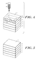
- FIG. 3 illustrates an alternative embodiment of sheet 2 having a second coating 8 extending over first coating 9, that in turn overlies substrate 4.
- Coating 8 may comprise either a polymeric material 10, or polymeric material 10 in combination with a particulate material 12.
- substrate 4 is laminated to backing 6.
- Coating 8 overlies coating 9 and is applied after coating 9 has sufficiently dried.
- Coating 8 is applied as a viscous fluid having, for example, a viscosity ranging from about 5 to 6 Pa.s (5000 to 6000 centipoise). After approximately twenty-five minutes at room temperature, the viscous fluid coagulates and forms a semi-solid layer having a height of approximately 0.1 micrometers.
- Coating 8 can be a natural or synthetic gum, a natural or synthetic thickener, a natural or synthetic polymer (e.g. CMC, HEC, or other thickeners), or a combination of natural and synthetic polymeric materials.
- the polymeric material of coating 8 can include gums, such as xanthan gum.
- coating 8 can comprise a polymeric material in a solution, such as deionized water.
- Both coating 8 and coating 9, either alone or in combination, advantageously hold ink pattern 20 in situ and enable the downward migration of ink 26 along ink diffusion path 22, rather than laterally through the coatings.
- This allows the direct transfer of ink pattern 20 to the surface of substrate 4 at a controlled rate thereby allowing ink 26 to be imbibed by substrate 4 with substantially no lateral diffusion, smearing, or spreading.
- Coatings 8 and 9, therefore, hold ink 26 and regulate the rate and/or facilitate the transfer of ink 26 into substrate 4.
- coating 8 contains a particulate 12, for example HPLC grade silica (manufactured by Waters Corp. under the brand name "Porasil”) or colloidal silica, that inhibits lateral diffusion of dye molecules within the polymeric material forming the coating.
- a particulate 12 for example HPLC grade silica (manufactured by Waters Corp. under the brand name "Porasil") or colloidal silica, that inhibits lateral diffusion of dye molecules within the polymeric material forming the coating.
- a particulate 12 is formed of xanthan gum and silica.
- particulates 12 each range from about 0.15 to 0.20 micrometers in diameter.
- the ratio of dye permeable, or polymeric material 10, to particulate 12 contained in coating 8 may be varied in order to effect the migration of ink from the top of coating 8 to the bottom of coating 8 and to limit the migration laterally across coating 8. As the ratio of particulate to dye permeable material rises less lateral migration occurs, and as the ratio of particulate to dye permeable material falls more lateral migration occurs.
- the ratio is modified according to various factors, including: the composition of ink 26, the thickness of coating 9, the thickness of coating 8, and the characteristics of ink dispenser 24 and ink 26. Generally, when particulates are incorporated into the coating, such particulates will range from about 0.35 to about 0.75 percent (by weight) of coating 8.
- the particulates 12 can also act as anti-blocking agents between a plurality of sheets 2.
- the particulates provide a roughened texture to the surfaces of the sheets 2 that weaken the surface tension formed between stacked sheets 2, thereby allowing the stacked sheets to be more easily separated. Without the roughened surface provided by the particulates 12, the strong adherence between stacked sheets can make separation of the sheets difficult.
- coated sheets not printed on within 24 hours can be prevented from drying out, in order that the coatings retain their properties. This may be prevented by wrapping sheet 2 in plastic within an hour after the coatings 8 and 9 have become solidified but retain moisture. Alternatively, sheet 2 can be overcoated with a strippable polymeric film coat to prevent excessive drying. A polymeric film coat applied within 24 hours retains the moisture in the coatings and can be easily removed prior to applying ink 26.
- ink 26 After ink 26 has been applied to sheet 2, it is allowed to dry.
- the drying time may be quite rapid or take one minute or longer.
- Various factors will influence the drying time, including the surface tension of ink 26, ink flow resulting from the various characteristics of ink dispenser 24, the thickness of coatings 8 and 9, and the density of ink pattern 20.
- the first coating 9 and the second coating 8 may both contain a fungicide to hinder the growth of various micro-organisms and mold.
- the fungicide kills micro-organisms and mold known to feed on polymeric material, thus preventing the same organisms from damaging and potentially destroying coating 8 or coating 9.
- coatings 8 and 9 can form temporary or permanent layers. If temporary, the coatings are generally water soluble to allow easy removal of the coatings. If permanent, the coatings typically are not water soluble or are subsequently overcoated to render the coatings 8 and/or 9 impervious to water damage. Furthermore, the permanent coatings should be transparent and have no significant capability of being dyed as a result of contact with the ink, in order to allow unobstructed viewing of the image or pattern created in substrate 4.
- FIG. 4 illustrates a sheet 2 according to this invention with permanent coatings 8 and 9 and a protective layer 16 applied after ink 26 has been imbibed by substrate 4 and allowed to dry.
- Protective layer 16 is formed by treating the top surface of coatings 8 or 9 with a hardener or cross linker designed to alter the polymeric material, thereby rendering coatings 8 or 9 less water-soluble and more durable.
- protective layer 16 can be water resistant, and scratch and abrasion resistant, thus preventing marks and indentations that would alter an observer's view of an image in substrate 4.
- protective layer 16 can be designed to absorb ultraviolet radiation in order to retard the fading of the images over time.
- Inks 26, in accordance with the invention, as defined in claim 26, can be formulated to permit rapid start-up in a printing head, provide smooth transfer during the spraying involved in ink-jet printing operations, and exhibit controlled drying on substrate 4 and coatings 8 and 9.
- Inks 26 comprise a de-salted dichroic dye, and preferably a mixture of deionized water and polyhydric alcohol in appropriate proportions to ensure controlled flowing and drying.
- One preferred polyhydric alcohol is diethylene glycol.
- the water to polyhydric alcohol ratio varies as a function of the type of ink dispenser being used. For example, in the case of the low end ink-jet printers (i.e.
- the ink composition can contain 85-90% water and correspondingly 15-10% polyhydric alcohol; and in the case of high end ink-jet printers (i.e. those with heaters) the ink compound can contain 90-95% water and correspondingly 10-5% polyhydric alcohol.
- Ink 26 can further include a complexing agent, such as ethylenediaminetetraacetate (hereinafter "EDTA"), or a preservative, such as dehydrosodium acetate.
- EDTA ethylenediaminetetraacetate
- a preservative such as dehydrosodium acetate.
- Complexing agents can be added to ink 26 to complex metals. Complexing agents, such as EDTA, can be obtained from Sigma Chemical Company of Saint Louis, Missouri.
- ink 26 may include both the complexing agent and the preservative. The complexing agent and the preservative combined account for no more than 0.2% (by weight) of the ink compound.
- the inks 26 used in printing, according to this invention contain water-soluble, salt-free, direct dyes of the azo type.
- the dyes chosen possess the property of dichroism, when properly oriented on substrate 4. Desalting the dyes used in the inks are accomplished using standard desalting methods such as dialysis, reverse phase chromatography, high-pressure liquid chromatography, reverse osmosis, and ultrafiltration.
- Cyan, Magenta and Yellow are Cyan, Magenta and Yellow (minus Red, minus Green, minus Blue).
- the Cyan dye comprises Direct Green #27 at 2.0% concentration
- the Magenta dye comprises a combination of 30% Direct Red #117 and 70% Sands Violet #9 at a total concentration of 1.0%
- the Yellow dye comprises a Primula Yellow from Hodagaya at 2.0% concentration.
- the particular grouping of dyes currently used for C,M,Y,K printing are Cyan, Magenta, Yellow, and Black.
- the Cyan, Magenta, and Yellows dyes are formed as disclosed above, and the Black dye comprises a Direct Black #170 at 3.0% concentration.
- the invention provides for an ink having a humectant that deters kogation.
- the humectant acts as a wetting agent.
- the humectant can reduce the loss of moisture from the ink through evaporation. Accordingly, the humectant ensures that the ink's viscosity remains stable.
- the humectant added to ink 26 is generally formed of a polyhydric alcohol.
- the humectants added to ink 26 can be selected from any of the following additives, or mixtures thereof, including: ethylene glycol, diethylene glycol, butylene glycol, 1,3-butylene glycol, propylene glycol, glycerine, dipropylene glycol, 2-methyl-1,3-propane diol, polyethylene glycols, polypropylene glycols, glycol derivatives, glycerol, mannitol, corn syrup, beta-cydodextrin, amylodextrin, amides, urea, substituted ureas, ethers, carboxylic acids, esters, alcohols, organosulfides, organosulfoxides, sulfones (such as sulfolane), alcohol derivatives, carbitol, butyl carbitol, cellusolve, ether derivatives, amino alcohol
- the humectant selected is formed of a glycol lacking an ether bond.
- those glycols having ether bonds such as diethylene glycol, and polyethylene glycol
- those glycols lacking an ether bond such as ethylene glycol, and glycerol
- ink 26 can include an additive that aids in the removal of deposited koga.
- an additive capable of breaking down the deposits formed when an ink undergoes thermal decomposition can be added to ink 26.
- a detergent capable of breaking down the deposits formed when an ink undergoes thermal decomposition can be added to ink 26.
- Such an additive breaks down the deposits due to thermal decomposition formed on the resistor element or in the channels of the thermal printer, thereby allowing the thermal printer to function at normal operating efficiency.
- additives are typically selected from one or more of the following materials, including: phosphates, phosphate esters, diphosphate, monomethyl phosphate, dimethyl phosphate, arsenate, molybdate, sulfite, and oxalate.
- Images can be transferred to sheet 2 using an ink-dispenser 24 consisting of gelatin relief images, as disclosed in the prior art.
- ink-dispenser 24 can be an electronic printer under the control of data processor 43.
- the electronic printers can have either continuous ink supplies or drop-on-demand ink supplies.
- a preferred ink-dispenser 24 is a thermal ink jet printer, such as those produced by the Hewlett-Packard Corporation of Palo Alto California.
- FIG. 5 shows a preferred stereoscopic polarizing image 3 having a 0.00762 cm. (0.003 inch) thick triacetate base 6, a first molecularly-oriented substrate 4 laminated to the top surface of base 6, and a second molecularly-oriented substrate 5 laminated to the bottom surface of base 6.
- Substrates 4 and 5 are oriented such that their respective molecular orientations are at opposing 45 degree angles to the running edge of base sheet 6 and at 90 degrees to each other.
- Coating 9 (as described herein) is mounted to the top of substrate 4, and a second coating 7 is mounted to the bottom of substrate 5.
- the combination of substrates 4 and 5, coatings 7 and 9, and base 6 result in a multilayer structure approximately 0.01016 cm. (0.004 inches) thick. This combination is thin enough to fit well within the tolerances of standard ink-jet printers.
- coating 9 is applied to the top surface of substrate 4 and a second coating 7 is applied to the bottom surface of substrate 5.
- sheet 3 is then coated with a strippable polymer coat to prevent excessive drying of coatings 7 and 9. At that point, sheet 3 can be slit and cut into units of suitable sizes for printing.
- This embodiment advantageously allows printing of a desired image or pattern to both sides of single sheet 3, thus removing any alignment problems when forming a stereoscopic polarizing image. Accordingly, sheet 3 is inserted into ink-dispenser 24 for application of a first image. After drying, sheet 3 is then flipped and reinserted into ink-dispenser 24 for application of a second image.
- This system forms a complete stereoscopic polarizing image having two differently polarized images laminated together without having to physically align and superimpose separately produced polarizing images.
- FIG. 6 illustrates a stereoscopic polarizing image 3 with a reflective layer 28 mounted to the bottom surface of stereoscopic polarizing image 3.
- Reflective layer 28 reflects rays of light entering the top of image 3 back through image 3 to provide an image of ink pattern 20 to an observer.
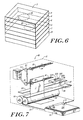
- FIG. 7 shows a double-sided printer 80, preferably an ink jet printer, used in applying ink 26 to a double-sided polarizing sheet 3.
- the printer 80 includes a housing 81 for supporting rollers 82, 84, 86, 88, 90, and 92.
- the housing 80 also supports track 98 for mounting the first printing head 94 and a second track 100 for mounting the second printing head 96.
- FIG. 7 further illustrates a printer having a motor 104, a paper cassette 106, and a paper feed 114.
- rollers 90 and 92 maintain tension on the sheet 3 and move the sheet across the printing zone formed between the first and second printing heads 92, 94. Rollers 90 and 92 also maintain tension on sheet 3 and prevent deformation of sheet 3.
- motors (not shown) can be connected to rollers 90 and 92 to aid in moving sheet 3 through the printer 80.
- Printer 80 also has a pair of substantially parallel tracks 98, 100.
- the first print head 94 is secured to the first track 98 and the second print head 96 is secured to the second track 100.
- a motor (not shown) is used to slide the print heads 94, 96 along their respective mounting tracks 98, 100.
- the print head 94, 96 move along tracks 98, 100 to sweep across the sheet 3.
- the print head 96 can include a single ink spray head, or multiple ink spray heads illustrated in Fig. 7 as items 102A, 102B, 102C, and 102D.
- Print head 94 similar to head 96, can include a single or multiple spray heads.
- the print heads are positioned on opposite side of the sheet 3 to allow for printing on both sides of sheets 3.
- print head 94 and 96 are moved along tracks 98 and 100 in tandem, such that the printer 80 applies ink to both sides of the sheet simultaneously.
- the tracks 98, 100 are oriented substantially horizontal. This allows the print heads 94, 96 to apply ink to a sheet 3 that is substantially vertical. By applying ink to the sheet 3 while it is vertically oriented, the ink is less likely to smear thereby creating an image on sheet 3 having greater precision and clarity.
- FIG. 7 also illustrates a cassette 106 holding a stack of sheets 108.
- the sheets are fed from the cassette 106 with the help of a roller 110.
- Roller 110 moves a single sheet from the stack 108 onto a paper feed 114.
- the paper feed 114 directs the movement of the sheet 3 into the space between rollers 90 and 92.
- Rollers 90 and 92 continue moving sheet 3 through the print space formed between print heads 94 and 96.
- the printer heads apply ink to sheet 3, the sheet is moved along by rollers 82, 84, 86, 88, 90, and 92, depending upon the length of the sheet.
- the double-sided printer 80 preferably has a paper handling system following rollers 90, 92 that allows the ink applied to both sides of the sheet 3 to dry.
- the paper handling system can be structured such that only the edges of the sheet 3 are contacted until the ink applied to sheet 3 dries.
- the printer shown in Fig. 7 can also include a controllable motor 104.
- Motor 104 turns a belt 112 that in turn effects movement of a gear 83 and a gear 85.
- Gear 83 is mounted to roller 82 and gear 85 is mounted to roller 86.
- roller 82 and roller 86 are rotated.
- motor 104 can be used to extract sheet 3 from the print zone.
- motor 104 can be paused while sheet 3 is being held between the roller pair 82, 84, and the roller pair 86, 88. This allows the ink on sheet 3 to dry without either side of sheet 3, except for the edges, being contacted.
- FIGS. 8 and 9 show further aspects of this invention concerned with the elimination of ghost images which at times can become objectionably apparent to an observer viewing digitized stereoscopic polarizing images and projections thereof.
- FIG. 8 illustrates a digitized stereoscopic polarizing image 50 producing a desired image 66 along with a ghost image 68 on a polarizing filter 62
- FIG. 9 illustrates a digitized stereoscopic polarizing image 50 forming the desired image 66 with a reduced ghost image 68 on a polarizing filter 62.
- Stereoscopic polarizing image 50 contains a first polarizing sheet 51 and a second polarizing sheet 56.
- the first polarizing sheet 51 is formed so that it can transmit light polarized along the direction of axis 52
- the second polarizing sheet 56 is formed so that it can transmit light polarized along the direction of axis 58.
- the degree to which the first and second polarizing sheets transmit polarized light depends upon the density of the image throughout the polarizing sheets. For example, areas of a polarizing sheet having a low pixel density will have a low polarizing efficiency, and areas of a polarizing sheet having a high pixel density will have a high polarizing efficiency.
- the unwanted light absorption or density in a first image 54 may make that first image observable through the analyzer 64, even though analyzer 64 is intended for viewing only a second image 60.
- this degree of imperfection is sufficiently great, ghost images which are observable by either or both eyes of an observer become objectionably apparent.
- the first polarizing sheet 51 contains a first image 54, shown as two parallel bands, and the second polarizing sheet 56 contains a second image 60, shown as an "H" FIG..
- FIG. 8 additionally illustrates a polarizing filter 62 having a polarizing axis 64 oriented with respect to stereoscopic polarizing image 50, so that only images polarized along axis 58 can be viewed.
- image 54 can be transmitted through polarizing sheet 56 and be viewed through filter 62. These imperfections cause the viewer to observe a desired image 66 and a ghost image 68 through the filter 62.
- polarizing sheet 51 is formed of of oriented molecules of polymeric material dichroic ink is deposited with the same orientation, but in practice this does not always occur.
- ink is not fully deposited with the same orientation the sheet 51 transmits an image 54 with non-polarized light.
- the non-polarized light that transmits image 54 is then viewed through analyzer 62 as the ghost image 68.
- objectionable ghost images When an edge of an area of relatively high density which is intended to be blocked from observation is in fact observable along an area of relatively low density of the image which is intended to be observed, the contrast becomes an objectionable ghost image. Under these conditions, it will be appreciated that objectionable ghost images will not be present under all conditions employing digitized stereoscopic polarizing images, and instead will be limited to particular scenes wherein a high density background of one image and a low density of the second image appear in overlapped relation.
- the ghost images may be reduced to a degree which can be tolerated, if not entirely eliminated, by building into either or the pair of light polarizing sheets 51, 56 a negative image of the other light polarizing stereoscopic image of said pair.
- the second polarizing sheet 56 can contain a second image 70 and an image 72, such that image 72 is representative of a negative of the first image 54.
- the negative image 72 reduces the appearance of the ghost image 68 when the digitized stereoscopic polarizing image is viewed through polarizer 62.
- this invention provides for a method of reducing the ghost image 68 by forming a first ink pattern representative of the image 70 superimposed with a negative image 72.
- This first ink pattern is applied with an ink-jet printer to the polarizing sheet 56, and the polarizing sheet 56 is then stereoscopically aligned with polarizing sheet 51 to form the digitized stereoscopic polarizing image 50, such that the negative image 72 reduces the ghost image 68 produced by light passing through polarizing sheet 51.
- the first ink pattern, representative of image 70 superimposed with negative image 72 can be formed by using a microprocessor or computer employing a image manipulating tool, such as the Adobe PhotoshopTM system, produced by the Adobe Corporation of Arizona.
- a data file representative of image 54 is stored in a memory element so that it can be easily manipulated and recovered at a later time.
- the digital representation of image 54 is retrieved from memory and inverted, thereby converting the digital representation into a negative image 72.
- the digital representations of image 70 and the negative image 72 are then merged together (e.g. by multiplying pixel values) to form a data file representative of image 70 superimposed with negative image 72.
- the pixel density of negative image 72 is controlled so that a background image 74 produced by the negative image 72 is well matched with the ghost image 68 produced by the first image 54.
- Pixel density of image 72 is preferably regulated so that the intensity of the ghost image 68 viewed through filter 62 is substantially equal to the intensity of the background image 74 viewed through filter 62. This control advantageously allows a complete elimination of the ghost image.
- the pixel density of the image is modified with the aid of a microprocessor or computer.
- a data file representative of the negative image 72 can be stored in a memory element and this data file can be manipulated so that the pixel density of the image is altered.
- the undesired condition resulting in the ghost image 68 may be substantially eliminated by increasing the density of the second image 70, i.e. the image intended to be observed through filter 62, in areas where the offensive overlapping becomes apparent.
- the system for producing the stereoscopic images increases the pixel density of the image 70 so that the image polarizes light to a greater degree and thus overpowers any objectionable overlapping ghost image and stands out in higher contrast relative to the background noise produced by ghost image 68 and background image 74.
- the system can further increase the contrast between the desired image 66 and the background image 74 during the formation of the negative image 72.
- the data file representative of the negative image 72 can be manipulated so that the brightness and contrast of the pixels forming the negative image 72 are reduced relative to the desired image 66.
- first image 54 and second image 70 are digitized and stored in a first memory element, and then the system manipulates the digitized images.
- the system can convert the first image 54 into a negative image 72 and store the data elsewhere within the first memory element.
- the negative image 72 is then multiplied with the second image 70 to form a first data set representing the combination of the second image with a negative first image.
- An ink-jet printer also under control of the system, can apply a first ink pattern representative of the first image 54 to a first oriented polymeric sheet, and can apply a second ink pattern to a second oriented polymeric sheet.
- the second ink pattern is preferably dictated by the first data set, so that an image equivalent to the superposition of the second image 70 and the negative image 72 is formed on the second polymeric sheet.
- the first and second polymeric sheets produce an image 66 and a substantially hidden ghost artifact 68.
- a negative of the second image 70 can be superimposed with the first image 54 on the first polarizing sheet 51 to remove a ghost image produced by the second polarizing sheet 56.
- a pair of polarizing sheets 51, 56 contain negative images representative of the image found on the other polarizing sheet of the pair. Accordingly, this reduces ghost images viewed through a pair of polarizing filters aligned to view the digitized stereoscopic polarizing image 50.
- ink-jet printing methods and systems in accordance with this invention greatly simplify the preparation of full-color stereoscopic polarizing images.
- Ink-jet printers unlike gelatin-based transfer systems, are compatible with digital imaging and can be used to provide polarizing stereoscopic reflective prints or transparencies from computer-generated or digitally-processed images, as well as from conventional photographic images that have been digitized.
- Stereoscopic light-polarizing images produced according to the techniques disclosed in this invention may be produced without the knowledge and use of photographic chemistry, as required with prior techniques. Stereoscopic prints produced in this manner have the added advantage of being easily and inexpensively modifiable. By simply altering the picture in the computer or digital imager, the stereoscopic image may be reprinted in its modified form.
Landscapes
- Engineering & Computer Science (AREA)
- Chemical & Material Sciences (AREA)
- Wood Science & Technology (AREA)
- Physics & Mathematics (AREA)
- Vascular Medicine (AREA)
- Life Sciences & Earth Sciences (AREA)
- General Health & Medical Sciences (AREA)
- Materials Engineering (AREA)
- Health & Medical Sciences (AREA)
- Organic Chemistry (AREA)
- General Engineering & Computer Science (AREA)
- Textile Engineering (AREA)
- General Physics & Mathematics (AREA)
- Theoretical Computer Science (AREA)
- Inks, Pencil-Leads, Or Crayons (AREA)
- Paints Or Removers (AREA)
- Stereoscopic And Panoramic Photography (AREA)
- Ink Jet (AREA)
- Ink Jet Recording Methods And Recording Media Thereof (AREA)
Abstract
Description
both transmits the image and polarizes the light passing through
Claims (55)
- A treated sheet material for recording a polarizing image, the treated sheet material comprising
a substrate having a top surface and a bottom surface, the substrate having molecules oriented parallel to a polarizing axis, and
an ink-permeable polymeric coating overlying the top surface of the substrate for transporting an ink from an upper surface of the coating to the substrate and for regulating the imbibition of the ink by the oriented molecules in the substrate, such that the imbibed ink forms the polarizing image in the substrate. - The material of claim 1, wherein the ink-permeable polymeric coating is a natural or synthetic gum or a cellulosic polymer.
- The material of claim 1, wherein the coating further comprises dispersed particulates for inhibiting lateral diffusion of ink molecules.
- The material of claim 1, wherein the coating is water soluble.
- The material of claim 1, wherein the coating further comprises a water-resistant upper protective layer.
- The material of claim 5, wherein the protective layer is scratch and abrasion resistant.
- The material of claim 5, wherein the protective layer absorbs ultra-violet radiation.
- The material of claim 1, wherein the coating further comprises a fungicide.
- The material of claim 1, wherein the substrate is formed of a stretched and oriented polymer.
- The material of claim 1, further comprising a second coating spanning the bottom surface of the substrate, the second coating being formed of an ink-permeable polymeric material for transporting ink molecules.
- The material of claim 10, wherein the substrate is formed of a first molecularly oriented sheet aligned along a first axis and a second molecularly oriented sheet aligned along a second axis, the second axis being substantially orthogonal to the first axis.
- An apparatus for manufacturing a digitized stereoscopic polarizing image from a first image of an object and a second image of the object from a point of view different from the first image, comprising
coating means for applying an ink-permeable polymeric coating to a substrate molecularly oriented primarily along a polarizing axis,
memory means for storing and retrieving a first digital data set representative of the first image and a second digital data set representative of the second image,
a data processing element coupled with the memory means for generating a flipped data set representative of a picture formed when the image representative by the first digital data set is flipped about an axis, and
printing means coupled with the data processing element for applying an ink to the coated substrate in a pattern forming an image associated with either the second data set or the flipped data set, such that a polarizing image is formed. - The apparatus of claim 12, wherein the data processing element further comprises means for altering a pixel density in the first digital data set.
- The apparatus of claim 13, wherein said means for altering pixel density comprises means for replaning a first pixel and a second pixel with a weighted average of said first and said second pixels.
- The apparatus of claim 13, wherein said means for altering pixel density comprises means for inserting between a first pixel and a second pixel a third pixel having characteristics determined by interpolating between said first and said second pixels.
- The apparatus of claim 12, wherein the data processing element further comprises means for stereoscopically aligning the first image represented by the first digital data set with a second image represented by a second digital data set.
- The apparatus of claim 16, wherein the data processing element further comprises ghost reduction means, the ghost reduction means including means for forming a third data set representative of the second image superimposed with a negative of the first image.
- The apparatus of claim 12, wherein the printing means is an ink jet printer.
- The apparatus of claim 12, further comprising aligning means coupled with said printing means for stereoscopically aligning the substrate with a second substrate.
- The apparatus of claim 19, further comprising laminating means coupled with said aligning means for laminating the back of the substrate to the back of the second substrate.
- The apparatus of claim 12, further comprising washing means coupled with the printing means for cleaning the substrate.
- The apparatus of claim 12, further comprising protecting means coupled with the printing means for applying a protective coating to the substrate.
- The apparatus of claim 12, wherein the coating is formed of an ink-permeable polymeric material for transporting an ink through the coating to the substrate and for regulating the imbibition of the ink by the substrate.
- The apparatus of claim 12, wherein the ink is an ink characterized by rapid start-up in a printing head and controlled drying on a molecularly oriented substrate.
- The apparatus of claim 12, wherein the printing means is a double-sided printer.
- An ink for use in an ink jet printer for staining a polymeric substrate, the ink comprising:wherein the ink is structured to provide smooth flowing through the ink jet printer.a salt-free dichroic, water soluble direct dye of the azo type, water anda humectant that acts as a wetting agent,
- The ink of claim 26, wherein the ink further comprises a complexing agent and/or a preservative and/or an additive for removing deposits within the ink jet printer.
- The ink of claim 26, wherein the humectant is formed of a glycol lacking an ether bond.
- The ink of claim 26, wherein the humectant is polyhydric alcohol or pyrrolidone.
- The ink of claim 26, wherein the humectant is selected from the group consisting of ethylene glycol, diethylene glycol, butylene glycol, 1,3-butylene glycol, propylene glycol, glycerine, dipropylene glycol, 2-methyl-1,3-propane diol, polyethylene glycols, polypropylene glycols, glycol derivatives, mannitol, corn syrup, beta-cyclodextrin, amylodextrin, amides, urea, substituted ureas, ethers, carboxylic acids, esters, alcohols, organosulfides, organosulfoxides, sulfones (such as sulfolane), alcohol derivatives, carbitol, butyl carbitol, cellosolve, ether derivatives, amino alcohols, ketones, sodium pyrrolidonecarboxylate, N-methylpyrrolidinone, 2-pyrrolidone, cyclohexylpyrrolidone, hydroxyethers, sulfoxides, and lactones.
- The ink of claim 26, wherein the drying time of the ink varies according to the ratio of the water to the humectant.
- The ink of claim 26, wherein the water comprises about 85% to 90% by weight of the ink and the humectant comprises about 10% to about 15% by weight of the ink
- The ink of claim 26, wherein the water comprises about 90% to 95% by weight of the ink and the humectant comprises about 5% to about 10% by weight of the ink.
- A method for producing a polarizing image comprising:providing a first sheet molecularly oriented primarily along a polarizing axis,coating the first molecularly oriented sheet with an ink-permeable coating that regulates imbibition of ink by the first sheet, andapplying a dichroic ink in a pattern of a first image to the ink-permeable coating, such that the ink forms the polarizing image in the first sheet.
- The method of claim 34, further comprising:generating a first digital data set representative of the first image, andstoring the first digital data set in a memory element.
- The method of claim 35, further comprising generating a flipped data set representative of a picture formed when the image represented by the first digital data set is flipped about an axis.
- The method of claim 35, further comprising the step of generating the first digital data set by digitally scanning the first image.
- The method of claim 35, further comprising the step of modifying the pixel density in the first digital data set.
- The method of claim 38, further comprising the steps of:determining a weighted average of the characteristics of a first pixel in the first digital data set and a second pixel in the first digital data set, andreplacing the first and second pixels with a third pixel having characteristics corresponding to said determined weighted average.
- The method of claim 38, further comprising the steps of:interpolating between a first pixel in the first digital data set and a second pixel in the first digital data set,generating a third pixel with characteristics corresponding to said interpolated values, andinserting the third pixel between the first pixel and the second pixel.
- The method of claim 34, further comprising the step of washing the first molecularly oriented sheet after said printing step.
- The method of claim 34, further comprising:forming a second image on a second molecularly oriented sheet, andstereoscopically aligning the first image with second image.
- The method of claim 42, further comprising the step of laminating the back of the first molecularly oriented sheet to the back of the second molecularly oriented sheet.
- The method of claim 34, further comprising the step of applying a protective coating to the front of the first molecularly oriented sheet.
- The method of claim 34, further comprising reducing a ghost image by:applying to a second molecularly oriented sheet a second ink pattern representative of a second image superimposed with a negative of the first image, andstereoscopically aligning the first and the second images on their respective molecularly oriented sheets.
- The method of claim 34, further comprising allowing a time for the ink to migrate through the coating and for the first molecularly oriented sheet to imbibe the ink.
- The method of claim 46, further comprising the step of determining the allowed time based on wetness of the ink, composition of the ink, thickness of the coating, and the density of the ink pattern.
- The method of claim 46, further comprising the step of removing the coating from the polymer sheet after the allowed time.
- The method of claim 34 further comprising the step of laminating a reflective non-depolarizing substrate to the bottom surface of the first molecularly oriented sheet.
- The method of claim 34, further comprising the step of forming the dichroic ink by dissolving the dichroic dye in de-ionized water and a humectant.
- The method of claim 50, further including the step of forming the dichroic ink by dissolving a dichroic dye in water and a humectant.
- The method of claim 51, further including the step of de-salting the dichroic dye.
- The method of claim 51, wherein the dye is desalted by high pressure liquid chromatography, or by reverse osmosis, or by ultra filtration, or by reverse phase chromatography.
- The method of claim 51, wherein the ratio of the deionized water to the humectant is controlled in order to vary the drying time of the dichroic ink.
- The method of claim 34, or the material of claim 1, wherein the coating has a thickness ranging from about 0.02 to about 0.03 µm.
Applications Claiming Priority (7)
| Application Number | Priority Date | Filing Date | Title |
|---|---|---|---|
| US380941 | 1995-01-31 | ||
| US380949 | 1995-01-31 | ||
| US381131 | 1995-01-31 | ||
| US08/380,941 US5591508A (en) | 1995-01-31 | 1995-01-31 | Coating methods and compositions for production of digitized stereoscopic polarizing images |
| US08/380,949 US5552182A (en) | 1995-01-31 | 1995-01-31 | Inking methods and compositions for production of digitized stereoscopic polarizing images |
| US08/381,131 US5764248A (en) | 1995-01-31 | 1995-01-31 | Production of digitized stereoscopic polarizing images by ink jet printing |
| PCT/US1996/001043 WO1996023663A1 (en) | 1995-01-31 | 1996-01-30 | Coating methods and compositions for production of digitized stereoscopic polarizing images |
Publications (3)
| Publication Number | Publication Date |
|---|---|
| EP0807024A1 EP0807024A1 (en) | 1997-11-19 |
| EP0807024B1 EP0807024B1 (en) | 1998-12-02 |
| EP0807024B2 true EP0807024B2 (en) | 2002-11-27 |
Family
ID=27409509
Family Applications (1)
| Application Number | Title | Priority Date | Filing Date |
|---|---|---|---|
| EP96903684A Expired - Lifetime EP0807024B2 (en) | 1995-01-31 | 1996-01-30 | Coating methods and compositions for production of digitized stereoscopic polarizing images |
Country Status (8)
| Country | Link |
|---|---|
| EP (1) | EP0807024B2 (en) |
| JP (1) | JPH11511702A (en) |
| AT (1) | ATE173978T1 (en) |
| AU (1) | AU4768996A (en) |
| CA (1) | CA2211626A1 (en) |
| DE (1) | DE69601072T3 (en) |
| ES (1) | ES2127624T5 (en) |
| WO (1) | WO1996023663A1 (en) |
Families Citing this family (5)
| Publication number | Priority date | Publication date | Assignee | Title |
|---|---|---|---|---|
| JP5749568B2 (en) * | 2010-05-28 | 2015-07-15 | 富士フイルム株式会社 | 3D image printing paper, 3D image printed material, 3D image printed material manufacturing method, and 3D image providing method |
| JP2014094548A (en) * | 2012-11-12 | 2014-05-22 | Mimaki Engineering Co Ltd | Method for manufacturing a laminate |
| US10070118B2 (en) * | 2015-09-17 | 2018-09-04 | Lumii, Inc. | Multi-view displays and associated systems and methods |
| JP7285824B2 (en) | 2017-08-09 | 2023-06-02 | ファゾム・オプティクス・インコーポレイテッド | Manufacture of light field prints |
| WO2022086527A1 (en) * | 2020-10-22 | 2022-04-28 | Hewlett-Packard Development Company, L.P. | Printing modes with drying delays |
Citations (3)
| Publication number | Priority date | Publication date | Assignee | Title |
|---|---|---|---|---|
| US2544659A (en) † | 1946-05-14 | 1951-03-13 | John F Dreyer | Dichroic light-polarizing sheet materials and the like and the formation and use thereof |
| US3650625A (en) † | 1966-10-31 | 1972-03-21 | Technical Animations Inc | Multiple automatic transfer of molecularly oriented motion patterns |
| US5106417A (en) † | 1989-10-26 | 1992-04-21 | Ciba-Geigy Corporation | Aqueous printing ink compositions for ink jet printing |
Family Cites Families (4)
| Publication number | Priority date | Publication date | Assignee | Title |
|---|---|---|---|---|
| BE465036A (en) * | 1940-06-07 | |||
| US5137773A (en) * | 1990-03-02 | 1992-08-11 | Xerox Corporation | Transparencies |
| DE69322714T2 (en) * | 1992-09-10 | 1999-07-22 | Canon K.K., Tokio/Tokyo | Ink jet recording method and apparatus |
| JP3330658B2 (en) * | 1992-12-24 | 2002-09-30 | 株式会社リコー | Image forming device |
-
1996
- 1996-01-30 DE DE69601072T patent/DE69601072T3/en not_active Expired - Fee Related
- 1996-01-30 JP JP8523632A patent/JPH11511702A/en active Pending
- 1996-01-30 WO PCT/US1996/001043 patent/WO1996023663A1/en not_active Ceased
- 1996-01-30 ES ES96903684T patent/ES2127624T5/en not_active Expired - Lifetime
- 1996-01-30 CA CA002211626A patent/CA2211626A1/en not_active Abandoned
- 1996-01-30 AU AU47689/96A patent/AU4768996A/en not_active Abandoned
- 1996-01-30 EP EP96903684A patent/EP0807024B2/en not_active Expired - Lifetime
- 1996-01-30 AT AT96903684T patent/ATE173978T1/en active
Patent Citations (3)
| Publication number | Priority date | Publication date | Assignee | Title |
|---|---|---|---|---|
| US2544659A (en) † | 1946-05-14 | 1951-03-13 | John F Dreyer | Dichroic light-polarizing sheet materials and the like and the formation and use thereof |
| US3650625A (en) † | 1966-10-31 | 1972-03-21 | Technical Animations Inc | Multiple automatic transfer of molecularly oriented motion patterns |
| US5106417A (en) † | 1989-10-26 | 1992-04-21 | Ciba-Geigy Corporation | Aqueous printing ink compositions for ink jet printing |
Also Published As
| Publication number | Publication date |
|---|---|
| WO1996023663A1 (en) | 1996-08-08 |
| DE69601072T3 (en) | 2003-08-21 |
| ES2127624T5 (en) | 2003-06-16 |
| EP0807024B1 (en) | 1998-12-02 |
| DE69601072D1 (en) | 1999-01-14 |
| DE69601072T2 (en) | 1999-08-12 |
| EP0807024A1 (en) | 1997-11-19 |
| AU4768996A (en) | 1996-08-21 |
| ATE173978T1 (en) | 1998-12-15 |
| MX9705770A (en) | 1997-10-31 |
| CA2211626A1 (en) | 1996-08-08 |
| ES2127624T3 (en) | 1999-04-16 |
| JPH11511702A (en) | 1999-10-12 |
Similar Documents
| Publication | Publication Date | Title |
|---|---|---|
| US6013123A (en) | Inking methods and compositions for production of digitized stereoscopic polarizing images | |
| US5764248A (en) | Production of digitized stereoscopic polarizing images by ink jet printing | |
| DE69427762T2 (en) | ABLATION TRANSFER TO INTERMEDIATE PRODUCTS | |
| DE69915787T2 (en) | Recording medium and method for its production | |
| DE69731490T2 (en) | COATINGS, MICROPOROUS, INK ROLLING MEDIA AND METHOD OF CHECKING THE POINT DIAM | |
| US6281270B1 (en) | Printing paper, dye-receiving layer forming composition for preparing it, ink composition suitable for it, and image forming method using them | |
| DE19546803C2 (en) | Method of manufacturing an ink jet recording medium | |
| AU2012265189B2 (en) | Printed device with three dimensional appearance | |
| JP2000141883A (en) | Ink jet recording method, recording material reproducing method, recording material, and ink | |
| US5758036A (en) | Production of improved digitized stereoscopic polarizing images | |
| US5552182A (en) | Inking methods and compositions for production of digitized stereoscopic polarizing images | |
| EP0807024B2 (en) | Coating methods and compositions for production of digitized stereoscopic polarizing images | |
| JPH1046049A (en) | Pigment and pigment ink using the same | |
| JPH071842A (en) | Production of multi-color donor element for thermal transfer system | |
| US5591508A (en) | Coating methods and compositions for production of digitized stereoscopic polarizing images | |
| MXPA97005770A (en) | Coating methods and compositions for production of digitized stereoscopic polarizing images | |
| DE60127788T2 (en) | Color checking by inkjet printing | |
| JPH05221112A (en) | Transparent recording sheet | |
| JPS60234879A (en) | Inkjet recording sheet | |
| JPH04320877A (en) | Recording sheet, recorded article and coating solution | |
| DE4126864C1 (en) | ||
| JP2007076034A (en) | Ink jet recording method and recorded matter | |
| JPS63317382A (en) | Method of developing overhead transparency printed by ink injection | |
| JPH0839925A (en) | Inkjet recording film and recording method using the same | |
| Graindourze et al. | A Study of the Print Gloss of Ink Jet Glossy Photo Papers |
Legal Events
| Date | Code | Title | Description |
|---|---|---|---|
| PUAI | Public reference made under article 153(3) epc to a published international application that has entered the european phase |
Free format text: ORIGINAL CODE: 0009012 |
|
| 17P | Request for examination filed |
Effective date: 19970822 |
|
| AK | Designated contracting states |
Kind code of ref document: A1 Designated state(s): AT BE CH DE DK ES FR GB GR IE IT LI LU MC NL PT SE |
|
| GRAG | Despatch of communication of intention to grant |
Free format text: ORIGINAL CODE: EPIDOS AGRA |
|
| 17Q | First examination report despatched |
Effective date: 19980122 |
|
| GRAG | Despatch of communication of intention to grant |
Free format text: ORIGINAL CODE: EPIDOS AGRA |
|
| GRAG | Despatch of communication of intention to grant |
Free format text: ORIGINAL CODE: EPIDOS AGRA |
|
| GRAH | Despatch of communication of intention to grant a patent |
Free format text: ORIGINAL CODE: EPIDOS IGRA |
|
| GRAH | Despatch of communication of intention to grant a patent |
Free format text: ORIGINAL CODE: EPIDOS IGRA |
|
| GRAA | (expected) grant |
Free format text: ORIGINAL CODE: 0009210 |
|
| AK | Designated contracting states |
Kind code of ref document: B1 Designated state(s): AT BE CH DE DK ES FR GB GR IE IT LI LU MC NL PT SE |
|
| PG25 | Lapsed in a contracting state [announced via postgrant information from national office to epo] |
Ref country code: NL Free format text: LAPSE BECAUSE OF FAILURE TO SUBMIT A TRANSLATION OF THE DESCRIPTION OR TO PAY THE FEE WITHIN THE PRESCRIBED TIME-LIMIT Effective date: 19981202 Ref country code: LI Free format text: LAPSE BECAUSE OF FAILURE TO SUBMIT A TRANSLATION OF THE DESCRIPTION OR TO PAY THE FEE WITHIN THE PRESCRIBED TIME-LIMIT Effective date: 19981202 Ref country code: GR Free format text: LAPSE BECAUSE OF NON-PAYMENT OF DUE FEES Effective date: 19981202 Ref country code: CH Free format text: LAPSE BECAUSE OF FAILURE TO SUBMIT A TRANSLATION OF THE DESCRIPTION OR TO PAY THE FEE WITHIN THE PRESCRIBED TIME-LIMIT Effective date: 19981202 Ref country code: BE Free format text: LAPSE BECAUSE OF FAILURE TO SUBMIT A TRANSLATION OF THE DESCRIPTION OR TO PAY THE FEE WITHIN THE PRESCRIBED TIME-LIMIT Effective date: 19981202 Ref country code: AT Free format text: LAPSE BECAUSE OF FAILURE TO SUBMIT A TRANSLATION OF THE DESCRIPTION OR TO PAY THE FEE WITHIN THE PRESCRIBED TIME-LIMIT Effective date: 19981202 |
|
| REF | Corresponds to: |
Ref document number: 173978 Country of ref document: AT Date of ref document: 19981215 Kind code of ref document: T |
|
| REG | Reference to a national code |
Ref country code: CH Ref legal event code: EP |
|
| REF | Corresponds to: |
Ref document number: 69601072 Country of ref document: DE Date of ref document: 19990114 |
|
| REG | Reference to a national code |
Ref country code: IE Ref legal event code: FG4D |
|
| PG25 | Lapsed in a contracting state [announced via postgrant information from national office to epo] |
Ref country code: LU Free format text: LAPSE BECAUSE OF NON-PAYMENT OF DUE FEES Effective date: 19990130 |
|
| ITF | It: translation for a ep patent filed | ||
| PG25 | Lapsed in a contracting state [announced via postgrant information from national office to epo] |
Ref country code: SE Free format text: LAPSE BECAUSE OF FAILURE TO SUBMIT A TRANSLATION OF THE DESCRIPTION OR TO PAY THE FEE WITHIN THE PRESCRIBED TIME-LIMIT Effective date: 19990302 Ref country code: PT Free format text: LAPSE BECAUSE OF FAILURE TO SUBMIT A TRANSLATION OF THE DESCRIPTION OR TO PAY THE FEE WITHIN THE PRESCRIBED TIME-LIMIT Effective date: 19990302 Ref country code: DK Free format text: LAPSE BECAUSE OF FAILURE TO SUBMIT A TRANSLATION OF THE DESCRIPTION OR TO PAY THE FEE WITHIN THE PRESCRIBED TIME-LIMIT Effective date: 19990302 |
|
| ET | Fr: translation filed | ||
| REG | Reference to a national code |
Ref country code: ES Ref legal event code: FG2A Ref document number: 2127624 Country of ref document: ES Kind code of ref document: T3 |
|
| NLV1 | Nl: lapsed or annulled due to failure to fulfill the requirements of art. 29p and 29m of the patents act | ||
| REG | Reference to a national code |
Ref country code: CH Ref legal event code: PL |
|
| PG25 | Lapsed in a contracting state [announced via postgrant information from national office to epo] |
Ref country code: MC Free format text: LAPSE BECAUSE OF NON-PAYMENT OF DUE FEES Effective date: 19990731 |
|
| PLBQ | Unpublished change to opponent data |
Free format text: ORIGINAL CODE: EPIDOS OPPO |
|
| PLBI | Opposition filed |
Free format text: ORIGINAL CODE: 0009260 |
|
| PLBF | Reply of patent proprietor to notice(s) of opposition |
Free format text: ORIGINAL CODE: EPIDOS OBSO |
|
| 26 | Opposition filed |
Opponent name: BOELENS, CHRISTIANUS WILHELMUS MARIA Effective date: 19990901 |
|
| PLBF | Reply of patent proprietor to notice(s) of opposition |
Free format text: ORIGINAL CODE: EPIDOS OBSO |
|
| PLBF | Reply of patent proprietor to notice(s) of opposition |
Free format text: ORIGINAL CODE: EPIDOS OBSO |
|
| PLBF | Reply of patent proprietor to notice(s) of opposition |
Free format text: ORIGINAL CODE: EPIDOS OBSO |
|
| REG | Reference to a national code |
Ref country code: GB Ref legal event code: IF02 |
|
| PLAW | Interlocutory decision in opposition |
Free format text: ORIGINAL CODE: EPIDOS IDOP |
|
| PLAW | Interlocutory decision in opposition |
Free format text: ORIGINAL CODE: EPIDOS IDOP |
|
| PGFP | Annual fee paid to national office [announced via postgrant information from national office to epo] |
Ref country code: IE Payment date: 20020620 Year of fee payment: 7 |
|
| PUAH | Patent maintained in amended form |
Free format text: ORIGINAL CODE: 0009272 |
|
| STAA | Information on the status of an ep patent application or granted ep patent |
Free format text: STATUS: PATENT MAINTAINED AS AMENDED |
|
| 27A | Patent maintained in amended form |
Effective date: 20021127 |
|
| AK | Designated contracting states |
Kind code of ref document: B2 Designated state(s): AT BE CH DE DK ES FR GB GR IE IT LI LU MC NL PT SE |
|
| PG25 | Lapsed in a contracting state [announced via postgrant information from national office to epo] |
Ref country code: IE Free format text: LAPSE BECAUSE OF NON-PAYMENT OF DUE FEES Effective date: 20030130 |
|
| ET3 | Fr: translation filed ** decision concerning opposition | ||
| REG | Reference to a national code |
Ref country code: ES Ref legal event code: DC2A Date of ref document: 20030218 Kind code of ref document: T5 |
|
| REG | Reference to a national code |
Ref country code: IE Ref legal event code: MM4A |
|
| REG | Reference to a national code |
Ref country code: ES Ref legal event code: PC2A |
|
| REG | Reference to a national code |
Ref country code: GB Ref legal event code: 732E |
|
| REG | Reference to a national code |
Ref country code: FR Ref legal event code: TP |
|
| PGFP | Annual fee paid to national office [announced via postgrant information from national office to epo] |
Ref country code: IT Payment date: 20060131 Year of fee payment: 11 |
|
| PGFP | Annual fee paid to national office [announced via postgrant information from national office to epo] |
Ref country code: GB Payment date: 20070125 Year of fee payment: 12 |
|
| PGFP | Annual fee paid to national office [announced via postgrant information from national office to epo] |
Ref country code: ES Payment date: 20070126 Year of fee payment: 12 |
|
| PGFP | Annual fee paid to national office [announced via postgrant information from national office to epo] |
Ref country code: DE Payment date: 20070228 Year of fee payment: 12 |
|
| PGFP | Annual fee paid to national office [announced via postgrant information from national office to epo] |
Ref country code: FR Payment date: 20070117 Year of fee payment: 12 |
|
| GBPC | Gb: european patent ceased through non-payment of renewal fee |
Effective date: 20080130 |
|
| PG25 | Lapsed in a contracting state [announced via postgrant information from national office to epo] |
Ref country code: DE Free format text: LAPSE BECAUSE OF NON-PAYMENT OF DUE FEES Effective date: 20080801 |
|
| REG | Reference to a national code |
Ref country code: FR Ref legal event code: ST Effective date: 20081029 |
|
| PG25 | Lapsed in a contracting state [announced via postgrant information from national office to epo] |
Ref country code: GB Free format text: LAPSE BECAUSE OF NON-PAYMENT OF DUE FEES Effective date: 20080130 |
|
| REG | Reference to a national code |
Ref country code: ES Ref legal event code: FD2A Effective date: 20080131 |
|
| PG25 | Lapsed in a contracting state [announced via postgrant information from national office to epo] |
Ref country code: FR Free format text: LAPSE BECAUSE OF NON-PAYMENT OF DUE FEES Effective date: 20080131 |
|
| PG25 | Lapsed in a contracting state [announced via postgrant information from national office to epo] |
Ref country code: ES Free format text: LAPSE BECAUSE OF NON-PAYMENT OF DUE FEES Effective date: 20080131 |
|
| PG25 | Lapsed in a contracting state [announced via postgrant information from national office to epo] |
Ref country code: IT Free format text: LAPSE BECAUSE OF NON-PAYMENT OF DUE FEES Effective date: 20070130 |