EP0806916B1 - Slotted tap and lentulo drill for dental post system - Google Patents
Slotted tap and lentulo drill for dental post system Download PDFInfo
- Publication number
- EP0806916B1 EP0806916B1 EP96904484A EP96904484A EP0806916B1 EP 0806916 B1 EP0806916 B1 EP 0806916B1 EP 96904484 A EP96904484 A EP 96904484A EP 96904484 A EP96904484 A EP 96904484A EP 0806916 B1 EP0806916 B1 EP 0806916B1
- Authority
- EP
- European Patent Office
- Prior art keywords
- post
- post hole
- drill
- wire
- tap
- Prior art date
- Legal status (The legal status is an assumption and is not a legal conclusion. Google has not performed a legal analysis and makes no representation as to the accuracy of the status listed.)
- Expired - Lifetime
Links
Images
Classifications
-
- A—HUMAN NECESSITIES
- A61—MEDICAL OR VETERINARY SCIENCE; HYGIENE
- A61C—DENTISTRY; APPARATUS OR METHODS FOR ORAL OR DENTAL HYGIENE
- A61C13/00—Dental prostheses; Making same
- A61C13/225—Fastening prostheses in the mouth
- A61C13/30—Fastening of peg-teeth in the mouth
-
- A—HUMAN NECESSITIES
- A61—MEDICAL OR VETERINARY SCIENCE; HYGIENE
- A61C—DENTISTRY; APPARATUS OR METHODS FOR ORAL OR DENTAL HYGIENE
- A61C5/00—Filling or capping teeth
- A61C5/30—Securing inlays, onlays or crowns
- A61C5/35—Pins; Mounting tools or dispensers therefor
-
- A—HUMAN NECESSITIES
- A61—MEDICAL OR VETERINARY SCIENCE; HYGIENE
- A61C—DENTISTRY; APPARATUS OR METHODS FOR ORAL OR DENTAL HYGIENE
- A61C5/00—Filling or capping teeth
- A61C5/40—Implements for surgical treatment of the roots or nerves of the teeth; Nerve needles; Methods or instruments for medication of the roots
-
- A—HUMAN NECESSITIES
- A61—MEDICAL OR VETERINARY SCIENCE; HYGIENE
- A61C—DENTISTRY; APPARATUS OR METHODS FOR ORAL OR DENTAL HYGIENE
- A61C5/00—Filling or capping teeth
- A61C5/50—Implements for filling root canals; Methods or instruments for medication of tooth nerve channels
Definitions
- This invention relates to a reverse lentulo drill according to the preamble of claim 1.
- a drill is known from DE-0,837,146.
- DE-0,837,146 describes a needle for removal of nerves from a tooth root canal.
- This needle comprises a first wire spiralling in a first direction and having barbed portions provided along part of its length.
- the needle further comprises a second wire spiralling in the opposite direction and intimately wrapped around a portion of the first wire.
- a lentulo drill which essentially comprises a spiral wire which sprays cement radially along the post hole.
- the cement can often be sprayed by the lentulo drill wire beyond the confines of the post hole. This is because of the centrifying action of the spiral -- no stop is found on a conventional lentulo drill.
- a lentulo drill comprising a shaft and an extending spiral wire with forward and apical ends characterised by having a first portion of the wire running from the forward end with a spiral configuration in either a clockwise or counter clockwise rotational direction and a second portion thereof running from the apical end with a reverse spiral configuration opposite that of said first portion such that cement radially sprayed from said second portion when operating said drill does not spray in an apical direction.
- the invention is useable in a method and system for inserting a dental post into a tooth root canal is provided.
- the method comprises the steps of cutting out a post hole in the tooth and inserting a threaded tap into the post hole for creating at least one groove along the hole.
- the tap includes at least one slot defined by a pair of flexible legs and running at least a portion of the length thereof for reducing stress along the post hole during threaded insertion.
- the tap is unthreaded from the post hole in order to reveal at least one groove that was formed by the slotted tap which runs along the post hole.
- Cement is placed either along the post hole or on the post itself and the post is finally threaded into the post hole.
- the slotted tap comprises a depending shaft and at least one flange located adjacent the shaft with a diameter that is larger than the diameter of the shaft.
- the tap is adapted to be received in the post hole with the flange seated along an annular tier formed in the hole.
- the post also includes a depending shaft and at least one flange to be selectively seated along the annular tier formed in the post hole.
- the specially designed lentulo drill is used to radially apply cement to the wall of the post hole prior to insertion of the dental post.
- the lentulo drill comprises a spiraled wire having a reverse spiral configuration along the most apical end thereof. This reverse spiral acts as a stop on the apical whipping of the cement during operation of the drill, thereby confining the placement of the cement to the length of the post hole along which the dental post is to be inserted.
- An aim of the invention is to provide a dental post system for a dental root canal in which cement is applied to the post hole utilizing a lentulo drill with a reverse spiral on the most apical end.
- the invention accordingly comprises the several steps and the relation of one or more such steps with respect to each of the others, the system embodying the features of construction, combination of elements, and arrangement of parts which are adapted to effect such steps, and the product or products which possess the characteristics, properties and relation of components, all as exemplified in the detailed disclosure hereinafter set forth, and the scope of the invention will be indicated in the claims.
- Post hole 17 is typically prepared by means of a cutting drill, a primary reamer and a countersink drill bit, as is well known in the art.
- the cutting drill is first used to prepare the post hole.
- the primary reamer is used next and comprises a rotating shaft which is contained in a conventional dental drill.
- the primary reamer is drilled into the post hole in order to widen the post hole to the desired diameter.
- the countersink drill bit comprises a shaft and a head having a plurality of annularly spaced teeth and the countersink drill bit is used in order to cut one or more preparations in the post hole.
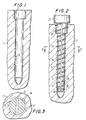
- post hole 17 includes a bore 15 and a tier 13.
- Slotted tap 19 comprises a shaft 21 formed unitarily with a body or flange member 23 that is connected to head 25.
- Shaft 21, body 23 and head 25 are all integrally connected together and formed as a unitary structure with a continuously running thread 33 formed along shaft 21 and body 23. Thread 33 is used to create a continuously running groove along the wall of post hole 15, as described below.
- Tap 19 is preferably made from stainless steel, titanium or titanium alloy.
- Shaft 21 is divided and separated into a desired plurality of substantially flexible legs exemplified in the drawing by two legs 27 and 29.
- Legs 27 and 29 are relatively spaced by a slot 31 that extends fully along the length of the shaft and body 23 where it terminates at head 25.
- Slot 31 is sized such as to permit legs 27 and 29 to absorb radial forces that are applied to the legs when shaft 19 is threaded into post hole 17, as shown in FIG. 2.
- tap 19 is selected in size to match the size of post hole 17 that was prepared by the primary reamer and countersink drill, as described above.
- Slotted tap 19 is threadingly inserted into post hole 17 by rotating head 25 in a conventional manner, preferably by hand, until tips 30 of legs 29 reach the apical end of post hole 15.
- Dental debris is collected in slot 31, as shown in FIG. 2, as tap 19 is threaded in post hole 17, which is later removed when tap 19 is unthreaded.
- a continuously running groove (see FIG. 5) is formed along the wall of post hole 15. Moreover, since legs 27 and 29 are flexible and spaced apart by slot 31, the legs absorb the threading torque and other forces produced during the threading operation in order to prevent the application of such forces and stresses to the wall of post hole 17. Consequently, the risk of fracture to tooth 11 is substantially reduced.
- post hole 17 Once threading of post hole 17 is completed, tap 19 is then unthreaded therefrom by rotating head 25 thereof in the opposite direction.
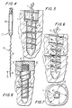
- Drill 37 is used for applying a dental cement along post hole 17 and comprises a shaft 39 which can be selectively retained in a powered dental handpiece, and an extending spiral wire 41.
- Wire 41 comprises a main wire portion 42, and apical wire portion 43 (identified in FIG. 4).
- main wire portion 42 includes a series of forward helical spirals.
- apical wire portion 43 includes a spiral wire configuration that is different from the rest of the wire 41, that is, it incorporates or comprises a reverse spiral wire configuration.
- main wire portion 42 will have a series of spirals which are in either a clockwise or counterclockwise rotational direction, while wire portion 43 will have a series of spirals with the opposite rotational direction.
- the reversed spiral wire configuration is no greater than 50% of the length of wire 41 that is inserted in post hole 17, as shown in FIG. 5.
- FIGS. 5 - 7 operation of lentulo drill 37 for applying a dental cement to post hole 17 is now described.
- Spiral wire 41 of drill 37 is inserted into post hole 17 (which now includes running groove 45 formed by tap 19) until the tip of wire 41 is located just below where post hole 17 begins to narrow (see FIG. 5).
- lentulo drill 37 is operated in order to rapidly rotate spiral wire 41, as shown in FIG. 7.
- Spiral wire 41 as alluded to above, has been previously dipped in or otherwise applied with an appropriate dental cement that is suitable for dental post application. Consequently, when wire 41 rotates, the applied cement is radially sprayed from wire 41 to the wall of post hole 17.
- wire portion 42 cement is sprayed radially in both a somewhat upward and downward direction (see arrows in top portion of FIG. 6).
- apical wire portion 43 has a reverse spiral configuration, cement is only radially sprayed therefrom in either a slightly up or sideways direction (see arrows in bottom portion of FIG. 6) -- no cement is sprayed below where post hole 17 along bore 15 begins to narrow.
- cement is placed only along the portion of the post hole where the dental post is to be inserted.
- a substantially solid dental post being not part of the invention, generally indicated at 51 is selected which matches the size of the post hole that has been prepared.
- the dental post is made from stainless steel, titanium, titanium alloy or gold.
- Dental post 51 comprises a body 55 sized to sit along tier 13 of post hole 17, an extending shaft 53 and a head 57. Shaft 53 and body 55 are formed with a continuous thread 59 which runs therealong and which is sized to engage running groove 45 formed along the wall of post hole 17.
- post 51 is threadingly inserted into post hole 17 until head 57 sits flush along the surface of tooth 11, body 55 rests along tier 13 and the end of shaft 53 is disposed along post hole 17 where post hole 17 begins to narrow -- see FIG. 8.
- a core material 63 is built up over head 57 of post 51, which may include a series of grooves 61 (vertical and horizontal) for facilitating engagement with the core material. Then, a crown 67 is placed over core material 63 in a conventional fashion.
Description
Claims (2)
- A lentulo drill (37) comprising a shaft (39) and an extending spiral wire (41) with forward and apical ends, said spiral wire having a first portion (42) of the wire running from the forward end with a spiral configuration in either a clockwise or counter clockwise rotational direction, characterized in that said spiral wire has a second portion (43) thereof running from the apical end with a reverse spiral configuration opposite that of said first portion such that cement radially sprayed from said second portion when operating said drill does not spray in an apical direction.
- The drill of Claim 2, wherein said second portion (43) has a length which is no greater than 50% of the length of said wire (41).
Priority Applications (1)
| Application Number | Priority Date | Filing Date | Title |
|---|---|---|---|
| EP01305636A EP1138274B1 (en) | 1995-01-31 | 1996-01-25 | Slotted tap and drill for dental post system |
Applications Claiming Priority (3)
| Application Number | Priority Date | Filing Date | Title |
|---|---|---|---|
| US08/381,428 US5669772A (en) | 1995-01-31 | 1995-01-31 | Slotted tap and lentulo drill for dental post system |
| US381428 | 1995-01-31 | ||
| PCT/US1996/000810 WO1996023453A1 (en) | 1995-01-31 | 1996-01-25 | Slotted tap and lentulo drill for dental post system |
Related Child Applications (1)
| Application Number | Title | Priority Date | Filing Date |
|---|---|---|---|
| EP01305636A Division EP1138274B1 (en) | 1995-01-31 | 1996-01-25 | Slotted tap and drill for dental post system |
Publications (3)
| Publication Number | Publication Date |
|---|---|
| EP0806916A1 EP0806916A1 (en) | 1997-11-19 |
| EP0806916A4 EP0806916A4 (en) | 2000-04-05 |
| EP0806916B1 true EP0806916B1 (en) | 2002-07-24 |
Family
ID=23504978
Family Applications (2)
| Application Number | Title | Priority Date | Filing Date |
|---|---|---|---|
| EP96904484A Expired - Lifetime EP0806916B1 (en) | 1995-01-31 | 1996-01-25 | Slotted tap and lentulo drill for dental post system |
| EP01305636A Expired - Lifetime EP1138274B1 (en) | 1995-01-31 | 1996-01-25 | Slotted tap and drill for dental post system |
Family Applications After (1)
| Application Number | Title | Priority Date | Filing Date |
|---|---|---|---|
| EP01305636A Expired - Lifetime EP1138274B1 (en) | 1995-01-31 | 1996-01-25 | Slotted tap and drill for dental post system |
Country Status (7)
| Country | Link |
|---|---|
| US (2) | US5669772A (en) |
| EP (2) | EP0806916B1 (en) |
| AU (1) | AU4857996A (en) |
| CA (1) | CA2207392C (en) |
| DE (2) | DE69622533T2 (en) |
| ES (2) | ES2178700T3 (en) |
| WO (1) | WO1996023453A1 (en) |
Families Citing this family (14)
| Publication number | Priority date | Publication date | Assignee | Title |
|---|---|---|---|---|
| US5803732A (en) * | 1995-01-31 | 1998-09-08 | Essential Dental Systems, Inc. | Slotted tap and lentulo drill for dental post system |
| US6634051B1 (en) | 1997-09-22 | 2003-10-21 | Centrix, Inc. | Disposable dental applicator |
| US6049934A (en) * | 1997-09-22 | 2000-04-18 | Centrix, Inc. | Disposable dental applicator |
| EP1124499B1 (en) * | 1998-10-30 | 2005-04-27 | Stuart Julian Filhol | Dental tool |
| FR2821000B1 (en) * | 2001-02-20 | 2003-08-22 | Jean Claude Rouiller | BORING INSTRUMENT, PARTICULARLY FOR BORING DENTAL CHANNELS |
| US6607533B2 (en) * | 2001-09-25 | 2003-08-19 | The Anspbell Effort, Inc | Miniature cutter shaft configuration |
| US6929475B1 (en) * | 2002-10-04 | 2005-08-16 | Centrix, Inc. | Pre-dosed applicator and applicator system |
| EP1734884B1 (en) | 2004-03-16 | 2021-06-16 | Guidance Endodontics, LLC | Endodontic files |
| USD736386S1 (en) * | 2013-04-24 | 2015-08-11 | Robert Sicurelli | Jacketed dental post |
| USD732669S1 (en) * | 2014-02-07 | 2015-06-23 | Nobel Biocare Services Ag | Dental abutment |
| USD732668S1 (en) * | 2014-02-07 | 2015-06-23 | Nobel Biocare Services Ag | Dental abutment |
| USD787061S1 (en) * | 2014-03-28 | 2017-05-16 | Dentsply International, Inc. | Scan body for dental implant procedures |
| AU363992S (en) | 2015-02-25 | 2015-09-08 | Nobel Biocare Services Ag | Dental implant abutment |
| US20190274786A1 (en) * | 2017-10-25 | 2019-09-12 | William L. Wildey | Root canal dental instrument |
Family Cites Families (13)
| Publication number | Priority date | Publication date | Assignee | Title |
|---|---|---|---|---|
| DE581004C (en) * | 1933-07-20 | Henri Lentulo | Filling device for narrow cavities, especially for tooth root canals | |
| US498554A (en) * | 1893-05-30 | Olop johanson | ||
| DE837146C (en) * | 1949-02-25 | 1952-04-21 | Fritz Drux | Flexible tooth root needle |
| US4260379A (en) * | 1979-05-17 | 1981-04-07 | Sybron Corporation | Endodontic instrument |
| US4457710A (en) * | 1979-08-03 | 1984-07-03 | Inventive Technology International | Dental instrument |
| USRE31948E (en) * | 1981-11-16 | 1985-07-16 | Dental post and wrench therefor and method of restoring bulk to a tooth root therewith | |
| US4490116A (en) * | 1984-01-04 | 1984-12-25 | Deutsch Allan S | Dental post and wrench therefor and method of restoring bulk to a tooth root therewith |
| CH673086A5 (en) * | 1987-09-08 | 1990-02-15 | Maillefer Auguste Sa | |
| GB9008515D0 (en) * | 1990-04-17 | 1990-06-13 | Kurer Hans G | Improvements in or relating to dentistry |
| US5083923A (en) * | 1990-06-04 | 1992-01-28 | Mcspadden John T | Method of obturating an extirpated root canal |
| US5236361A (en) * | 1991-03-27 | 1993-08-17 | Mays Ralph C | Dental post |
| US5275563A (en) * | 1992-09-02 | 1994-01-04 | Essential Dental Systems, Inc. | Dental post extracting drill |
| US5348476A (en) * | 1993-11-24 | 1994-09-20 | Essential Dental Systems, Inc. | System for fabrication of dental cast post and core using a burn-out post |
-
1995
- 1995-01-31 US US08/381,428 patent/US5669772A/en not_active Expired - Lifetime
-
1996
- 1996-01-25 CA CA002207392A patent/CA2207392C/en not_active Expired - Lifetime
- 1996-01-25 WO PCT/US1996/000810 patent/WO1996023453A1/en active IP Right Grant
- 1996-01-25 EP EP96904484A patent/EP0806916B1/en not_active Expired - Lifetime
- 1996-01-25 DE DE69622533T patent/DE69622533T2/en not_active Expired - Lifetime
- 1996-01-25 ES ES96904484T patent/ES2178700T3/en not_active Expired - Lifetime
- 1996-01-25 EP EP01305636A patent/EP1138274B1/en not_active Expired - Lifetime
- 1996-01-25 ES ES01305636T patent/ES2188577T3/en not_active Expired - Lifetime
- 1996-01-25 AU AU48579/96A patent/AU4857996A/en not_active Abandoned
- 1996-01-25 DE DE69625726T patent/DE69625726T2/en not_active Expired - Lifetime
- 1996-05-13 US US08/645,263 patent/US5632620A/en not_active Expired - Lifetime
Also Published As
| Publication number | Publication date |
|---|---|
| CA2207392C (en) | 2002-09-10 |
| EP0806916A4 (en) | 2000-04-05 |
| US5632620A (en) | 1997-05-27 |
| ES2178700T3 (en) | 2003-01-01 |
| US5669772A (en) | 1997-09-23 |
| AU4857996A (en) | 1996-08-21 |
| ES2188577T3 (en) | 2003-07-01 |
| CA2207392A1 (en) | 1996-08-08 |
| EP1138274A1 (en) | 2001-10-04 |
| DE69625726T2 (en) | 2003-10-16 |
| DE69622533D1 (en) | 2002-08-29 |
| EP1138274B1 (en) | 2003-01-08 |
| DE69625726D1 (en) | 2003-02-13 |
| DE69622533T2 (en) | 2003-03-20 |
| EP0806916A1 (en) | 1997-11-19 |
| WO1996023453A1 (en) | 1996-08-08 |
Similar Documents
| Publication | Publication Date | Title |
|---|---|---|
| EP0806916B1 (en) | Slotted tap and lentulo drill for dental post system | |
| US5897319A (en) | Self-tapping implant with helical flutes | |
| CA2093900C (en) | Dental implant having cutting means | |
| US8777949B2 (en) | Trocar-tipped drill bit | |
| US4449937A (en) | Dental anchor | |
| US4767332A (en) | Threaded dental anchor | |
| US6572373B2 (en) | Dental endosseous implant | |
| US4990088A (en) | Dental tool combining reamer and router | |
| US20030165796A1 (en) | Self-drilling implant | |
| EP1075228B1 (en) | Non circular endodontic instruments | |
| US4729736A (en) | Contoured dental posts | |
| JPH06500253A (en) | Dental post with interrupted thread | |
| JPH09253092A (en) | Drilling method for root canal of tooth and appliance set for executing this method | |
| US5145373A (en) | Endodontic post | |
| US5017137A (en) | Dental tool reamer capable of following natural curvature of tooth canal | |
| US5820375A (en) | Dental post having cutting and non-cutting surfaces | |
| US4284406A (en) | Dental tooth bur | |
| US5051092A (en) | Dental anchor and a drill for use therewith | |
| US5803732A (en) | Slotted tap and lentulo drill for dental post system | |
| EP0955015B1 (en) | Dental implant | |
| US4408990A (en) | Endodontic dental implant | |
| US5035620A (en) | Endodontic post with spiral groove | |
| CA2388695C (en) | Slotted tap and lentulo drill for dental post system | |
| US5944529A (en) | Two-component dental post system |
Legal Events
| Date | Code | Title | Description |
|---|---|---|---|
| PUAI | Public reference made under article 153(3) epc to a published international application that has entered the european phase |
Free format text: ORIGINAL CODE: 0009012 |
|
| 17P | Request for examination filed |
Effective date: 19970731 |
|
| AK | Designated contracting states |
Kind code of ref document: A1 Designated state(s): CH DE ES FR GB IT LI |
|
| A4 | Supplementary search report drawn up and despatched |
Effective date: 20000217 |
|
| AK | Designated contracting states |
Kind code of ref document: A4 Designated state(s): CH DE ES FR GB IT LI |
|
| RIC1 | Information provided on ipc code assigned before grant |
Free format text: 7A 61C 8/00 A, 7A 61C 13/30 B |
|
| 17Q | First examination report despatched |
Effective date: 20010509 |
|
| GRAG | Despatch of communication of intention to grant |
Free format text: ORIGINAL CODE: EPIDOS AGRA |
|
| GRAG | Despatch of communication of intention to grant |
Free format text: ORIGINAL CODE: EPIDOS AGRA |
|
| GRAH | Despatch of communication of intention to grant a patent |
Free format text: ORIGINAL CODE: EPIDOS IGRA |
|
| GRAH | Despatch of communication of intention to grant a patent |
Free format text: ORIGINAL CODE: EPIDOS IGRA |
|
| GRAA | (expected) grant |
Free format text: ORIGINAL CODE: 0009210 |
|
| AK | Designated contracting states |
Kind code of ref document: B1 Designated state(s): CH DE ES FR GB IT LI |
|
| REG | Reference to a national code |
Ref country code: GB Ref legal event code: FG4D |
|
| REG | Reference to a national code |
Ref country code: CH Ref legal event code: EP |
|
| REF | Corresponds to: |
Ref document number: 69622533 Country of ref document: DE Date of ref document: 20020829 |
|
| REG | Reference to a national code |
Ref country code: CH Ref legal event code: NV Representative=s name: RITSCHER & PARTNER AG PATENTANWAELTE |
|
| ET | Fr: translation filed | ||
| REG | Reference to a national code |
Ref country code: ES Ref legal event code: FG2A Ref document number: 2178700 Country of ref document: ES Kind code of ref document: T3 |
|
| PLBE | No opposition filed within time limit |
Free format text: ORIGINAL CODE: 0009261 |
|
| STAA | Information on the status of an ep patent application or granted ep patent |
Free format text: STATUS: NO OPPOSITION FILED WITHIN TIME LIMIT |
|
| 26N | No opposition filed |
Effective date: 20030425 |
|
| REG | Reference to a national code |
Ref country code: CH Ref legal event code: PCAR Free format text: RITSCHER & PARTNER AG;RESIRAIN 1;8125 ZOLLIKERBERG (CH) |
|
| REG | Reference to a national code |
Ref country code: CH Ref legal event code: PFA Owner name: ESSENTIAL DENTAL SYSTEMS, INC., US Free format text: FORMER OWNER: ESSENTIAL DENTAL SYSTEMS, INC., US |
|
| REG | Reference to a national code |
Ref country code: FR Ref legal event code: PLFP Year of fee payment: 20 |
|
| PGFP | Annual fee paid to national office [announced via postgrant information from national office to epo] |
Ref country code: ES Payment date: 20141211 Year of fee payment: 20 |
|
| PGFP | Annual fee paid to national office [announced via postgrant information from national office to epo] |
Ref country code: DE Payment date: 20150120 Year of fee payment: 20 Ref country code: CH Payment date: 20150114 Year of fee payment: 20 Ref country code: IT Payment date: 20150112 Year of fee payment: 20 |
|
| PGFP | Annual fee paid to national office [announced via postgrant information from national office to epo] |
Ref country code: GB Payment date: 20150121 Year of fee payment: 20 Ref country code: FR Payment date: 20150108 Year of fee payment: 20 |
|
| REG | Reference to a national code |
Ref country code: DE Ref legal event code: R071 Ref document number: 69622533 Country of ref document: DE |
|
| REG | Reference to a national code |
Ref country code: CH Ref legal event code: PL |
|
| REG | Reference to a national code |
Ref country code: GB Ref legal event code: PE20 Expiry date: 20160124 |
|
| PG25 | Lapsed in a contracting state [announced via postgrant information from national office to epo] |
Ref country code: GB Free format text: LAPSE BECAUSE OF EXPIRATION OF PROTECTION Effective date: 20160124 |
|
| REG | Reference to a national code |
Ref country code: ES Ref legal event code: FD2A Effective date: 20160503 |
|
| PG25 | Lapsed in a contracting state [announced via postgrant information from national office to epo] |
Ref country code: ES Free format text: LAPSE BECAUSE OF EXPIRATION OF PROTECTION Effective date: 20160126 |