EP0806862A2 - Bildprozessor zur Verarbeitung von Verarbeitungsmedien unterschiedlicher Formate - Google Patents
Bildprozessor zur Verarbeitung von Verarbeitungsmedien unterschiedlicher Formate Download PDFInfo
- Publication number
- EP0806862A2 EP0806862A2 EP97201213A EP97201213A EP0806862A2 EP 0806862 A2 EP0806862 A2 EP 0806862A2 EP 97201213 A EP97201213 A EP 97201213A EP 97201213 A EP97201213 A EP 97201213A EP 0806862 A2 EP0806862 A2 EP 0806862A2
- Authority
- EP
- European Patent Office
- Prior art keywords
- imaging
- medium
- receptacle
- receiving
- processor
- Prior art date
- Legal status (The legal status is an assumption and is not a legal conclusion. Google has not performed a legal analysis and makes no representation as to the accuracy of the status listed.)
- Granted
Links
Images


Classifications
-
- H—ELECTRICITY
- H04—ELECTRIC COMMUNICATION TECHNIQUE
- H04N—PICTORIAL COMMUNICATION, e.g. TELEVISION
- H04N1/00—Scanning, transmission or reproduction of documents or the like, e.g. facsimile transmission; Details thereof
- H04N1/04—Scanning arrangements, i.e. arrangements for the displacement of active reading or reproducing elements relative to the original or reproducing medium, or vice versa
- H04N1/06—Scanning arrangements, i.e. arrangements for the displacement of active reading or reproducing elements relative to the original or reproducing medium, or vice versa using cylindrical picture-bearing surfaces, i.e. scanning a main-scanning line substantially perpendicular to the axis and lying in a curved cylindrical surface
- H04N1/08—Mechanisms for mounting or holding the sheet around the drum
- H04N1/0804—Holding methods
- H04N1/0817—Holding sides of the sheet which are substantially perpendicular to the drum axis
-
- H—ELECTRICITY
- H04—ELECTRIC COMMUNICATION TECHNIQUE
- H04N—PICTORIAL COMMUNICATION, e.g. TELEVISION
- H04N1/00—Scanning, transmission or reproduction of documents or the like, e.g. facsimile transmission; Details thereof
- H04N1/04—Scanning arrangements, i.e. arrangements for the displacement of active reading or reproducing elements relative to the original or reproducing medium, or vice versa
- H04N1/06—Scanning arrangements, i.e. arrangements for the displacement of active reading or reproducing elements relative to the original or reproducing medium, or vice versa using cylindrical picture-bearing surfaces, i.e. scanning a main-scanning line substantially perpendicular to the axis and lying in a curved cylindrical surface
- H04N1/08—Mechanisms for mounting or holding the sheet around the drum
- H04N1/083—Holding means
- H04N1/0839—Mechanical clamps, i.e. means for holding the sheet against the drum by mechanical force
-
- H—ELECTRICITY
- H04—ELECTRIC COMMUNICATION TECHNIQUE
- H04N—PICTORIAL COMMUNICATION, e.g. TELEVISION
- H04N1/00—Scanning, transmission or reproduction of documents or the like, e.g. facsimile transmission; Details thereof
- H04N1/04—Scanning arrangements, i.e. arrangements for the displacement of active reading or reproducing elements relative to the original or reproducing medium, or vice versa
- H04N1/06—Scanning arrangements, i.e. arrangements for the displacement of active reading or reproducing elements relative to the original or reproducing medium, or vice versa using cylindrical picture-bearing surfaces, i.e. scanning a main-scanning line substantially perpendicular to the axis and lying in a curved cylindrical surface
- H04N1/08—Mechanisms for mounting or holding the sheet around the drum
- H04N1/083—Holding means
- H04N1/0869—Holding means capable of holding different sized sheets
Definitions
- the invention relates generally to the field of lathe bed scanners utilizing a rotating imaging drum for maintaining the positional relationship of donor element and receiver elements during the writing process and, more particularly, to such imaging drums having two movable, multi-positional rings for permitting retention of various widths of receiver and donor elements on the drum.
- Color-proofing is the procedure used by the printing industry for creating representative images that replicate the appearance of printed images without the cost and time required to actually set up a high-speed, high-volume printing press to print an example of the images intended.
- One such color proofer is a lathe bed scanner which utilizes a thermal printer having half-tone capabilities. This printer is arranged to form an image on a thermal print medium, or writing element, in which a donor transfers a dye to the writing element upon a sufficient amount of thermal energy.
- This printer includes a plurality of diode lasers which can be individually modulated to supply energy to selected areas of the medium in accordance with an information signal.
- a print-head includes one end of a fiber optic array having a plurality of optical fibers that are coupled to the diode lasers for transmitting the signals from the laser to the print head .
- the writing element is supported on a rotatable imaging drum, and the print-head with the fiber optic array is movable relative to the longitudinal axis of the drum.
- the dye is transferred to the writing element as the radiation, transferred from the diode lasers to the donor element by the optical fibers, is converted to thermal energy in the donor element.
- the cylindrical-shaped imaging drum includes a lip portion at both ends having a depth substantially equal to the depth of the writing element for supporting the writing element therein.
- the donor which is slightly wider in width than the writing element, rests its center portion atop the writing element with its edges resting on the lip portions. This configuration eliminates any crease from occurring at the edges of the donor as they are drawn over the writing element during the loading of the donor. Such creases create undesirable effects on the writing element during printing.
- the lip portions are permanently affixed to the imaging drum at its ends, and when a narrow-width writing element is placed on the drum, a gap is created between each lip portion and the edge of the writing element to which it is adjacent.
- the donor is placed atop the writing element with its center portion atop the writing element, and it extends outwardly over the gap so that its edges rest atop the lip portion. Consequently, the donor will not have adequate support at its portion directly above the gap . This will obviously result in undesirable creases in the donor sheet.
- a new imaging drum with a smaller width between the lip portions may be installed. This is also undesirable due to the cost of a new drum, downtime and the labor required to install it.
- the present invention is directed to overcoming one or more of the problems set forth above.
- the invention resides in an imaging processor for receiving a medium for processing.
- the processor comprises an imaging receptacle having a rigidly attached lip portion for receiving an edge of the medium; and a movable stop disposed on and magnetically attracted toward said receptacle for receiving a second edge of the medium for permitting the retention of medium of various dimensions.
- a lathe bed scanner 10 of the present invention having a housing 15 for forming a protective cover.
- a movable, hinged door 20 is attached to a front portion of the housing 15 for permitting access to two media trays, a lower tray 30a and upper tray 30b, that are positioned in an interior portion of the housing 15 for supporting receiver material 40, typically paper, thereon.
- receiver material 40 typically paper
- the lower media tray 30a includes a cam 50a for lifting the paper 40 upwardly toward a rotatable, lower media roller 60a and, ultimately, toward a second rotatable, upper media roller 60b which, when both are rotated, permits the receiver material 40 to be pulled upwardly towards a media guide 70.
- the upper media tray 30b also includes a cam 50b for lifting the receiver material 40 toward the upper media roller 60b which directs it towards the media guide 70.
- the movable media guide 70 directs the receiver material 40 under a pair of rollers 80 which engages the receiver material 40 for assisting the upper media roller 60b in directing it onto a staging tray 90.
- the media guide 70 is attached and hinged to the interior of the housing 15 at one end, and is uninhibited at its other end for permitting multiple positioning of the media guide 70.
- the media guide 70 then rotates its uninhibited end downwardly, as illustrated by the solid line, and the direction of rotation of the upper media roller 60b is reversed for forcing the receiver material 40 resting on the staging tray 90 back under the rollers 80, upwardly through an entrance passageway 100 and around a rotatable imaging drum 110.
- each roll includes a donor material 120 of a different color, typically black, yellow, magenta and cyan. These donor materials are ultimately cut into sheets and passed to the imaging drum for forming a medium from which dyes imbedded therein are passed to the receiver material resting thereon, which process is described in detail herein below.
- a drive mechanism 140 is attached to each roll 120, and includes three rollers 150 through which the donor material 120 of interest is rolled upwardly into a knife assembly 160.
- the rollers 150 cease driving the donor material 120 and two blades 170 positioned at the bottom portion of the knife assemble cut the donor material 120 into a sheet.
- the media rollers 60a and 60b and media guide 70 then pass the donor material 120 onto the drum 110 and in registration with the receiver material 40 using the same process as described above for passing the receiver material 40 onto the drum 110.
- the donor material 120 rests atop the receiver material 40 with a narrow gap between the two created by microbeads imbedded into the receiver material 40.
- a laser assembly 180 includes twenty lasers 185 in its interior, and these lasers are connected via fiber optic cables 187 to a coupling head 190 and ultimately to a write head 200.
- the write head 200 creates thermal energy from the signal received from the lasers 185 causing the donor material 120 to pass its dye across the gap to the receiver material 40.
- the write head 200 is attached to a lead screw 210 via a nut (not shown in Fig. 1) for permitting it to move axially along the longitudinal axis of the drum 110 for writing data onto the receiver material 40.
- the drum 110 rotates at a constant velocity, and the write head 200 begins at one end of the receiver material 40 and traverses the entire length of the receiver material 40 for completing the transfer process for the particular donor material resting on the receiver material 40.
- the donor material 120 is then transferred from the drum 110 and out of the housing 15 via a skive or ejection chute 210.
- the donor material eventually comes to rest on a donor material tray 212 for permitting removal by a user.
- the above-described process is then repeated for the other three rolls of donor material.
- the receiver material 40 is transported via a transport mechanism 220 through an entrance door 230 and into a dye binding assembly 240 where it rests against an exit door 250.
- the entrance door 230 is opened for permitting the receiver material 40 to enter into the dye binding assembly 240, and shuts once it comes to rest in the dye binding assembly 240.
- the dye binding assembly 240 heats the receiver material 40 for further binding the transferred dye on the receiver material 40 and for sealing the microbeads thereon.
- the exit door 250 is opened and the receiver material 40 with the image thereon passes out of the housing 15 and comes to rest against a stop 260.
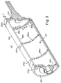
- FIG. 2 there is illustrated a perspective view of the imaging drum 110 and write head 200 of the lathe bed scanner 10.
- the imaging drum 110 is mounted for rotation about an axis (x) in a frame support 270.
- the write head 200 is movable with respect to the imaging drum 110, and is arranged to direct a beam of actinic light to the donor material 120 (shown in Fig. 1).
- the write head 200 contains therein a plurality of writing elements (not shown) which can be individually modulated by electronic signals from the laser diodes 185, which signals are representative of the shape and color of the original image, so that each dye is heated to cause volatilization only in those areas in which its presence is required on the receiver material 40 to reconstruct the color of the original object.
- the write head 200 is mounted on a movable translator member 280 which, in turn, is supported for low friction slidable movement on bars 290 and 300.
- the bars 290 and 300 are sufficiently rigid so that they do not sag or distort between the mounting points at their ends and are arranged as parallel as possible with the axis (x) of the imaging drum 110.
- the upper bar 300 is arranged to locate the axis of the writing head 200 precisely on the axis (x) of the drum 110 with the axis of the writing head perpendicular to the drum axis (x).
- the upper bar 300 locates the translator member 280 in the vertical and the horizontal directions with respect to the axis of the drum 110.
- the lower bar 290 locates the translator member 280 only with respect to rotation of the translator about the bar 290 so that there is no over-constraint of the translator member 280 which might cause it to bind, chatter, or otherwise impart undesirable vibration to the writing head 200 during the generation of an image.
- the drum 110 includes a cylindrical-shaped housing 310 partially enclosed on both ends by an end plate 320.
- the housing 310 includes an outer surface 330, an inner surface 340 and an interior portion 350 therebetween.
- Four circular-shaped magnets 360a, 360b, 360c, and 360d are embedded into the interior portion 350, and extend around the entire circumference of the housing 310.
- Each magnet 360 includes a plurality of both north and south poles alternately positioned thereon.
- Two movable, multiple-position, metallic rings 370a and 370b are positioned circumferentially on the outer surface 330 of the housing 310, and are respectively attracted magnetically to the magnets 360c and 360d for maintaining them in their outer position, as indicated by the solid lines.
- Each ring 370 includes a depth (d) that is slightly greater than the depth of a receiver material 40, typically .2 millimeters, for supporting the receiver material 40 therebetween.
- the donor material 120 includes a width that is slightly greater than the receiver material 40, and rests with its center portion abutting the receiver material 40 and its two outer edges resting respectively on the rings 370.
- the rings 370 are manually slidable along the outer surface 330 for permitting the user to position them at a plurality of positions on the outer surface 330. It will be apparent to those skilled in the art that less friction exists between the outer surface 330 and the rings 370 when they are not positioned directly over any of the magnets 360 for permitting efficient manual movement, and the friction reaches its maximum when the rings 370 are directly over a magnet 360.
- the rings 370 are semi-rigidly attached to the housing 310 when they are directly over a magnet 360 for permitting them to be maintained in this position when the drum 110 is operating. Although only four magnets 360 are shown, a plurality of such magnets 360 may be placed in the interior portion 350 for permitting the rings 370 to be placed at each of these locations.
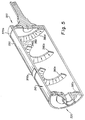
- each ring 370a and 370b is manually moved inwardly toward the center of the drum and respectively over the magnet 360a and 360b, the dashed ring position.
- the dashed ring 370 position is pre-selected so that the narrow-width receiver material 40 (not shown in Figs. 3 and 4) matingly and snugly fits between the rings 370 without creating a gap therebetween.
- the receiver material 40 is placed between the rings 370 and the donor material 120 is placed with its center portion on the receiver material 40 and its edges on the rings 370. This configuration permits the imaging drum 110 to receive a plurality of various-size donor 120 and receiver material 40.
- annular-shaped magnets 380a, 380b, 380c and 380d are disposed abutting against the inner surface 340 of the housing 310.
- Such annular-shaped magnets 380 perform the same function for magnetically attracting the rings 370 as the magnets 360 in Fig. 3.
- a plurality of such magnets 380 may be placed against the inner surface 340 for permitting the rings 370 to be placed at each of these locations.
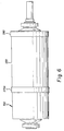
- an additional alternative embodiment includes substituting either of the rings 370 with a lip portion 390 permanently attached at one end of the housing; the other ring, 370a in this example, remains slidable along the outer surface 330 as described above.
- the housing 310 is preferably made of a ferro-magnetic material (such as iron), and a magnet 400 having a plurality of poles is placed over the housing 310 for magnetically attracting it to the housing 310 and for receiving one edge of the receiver material 40.
- the magnet 400 is also slidable over the outer surface 330 for permitting it to be positioned in a plurality of positions thereon.
- the lip portion 390 is permanently attached to the housing 310 at one end for receiving the opposite edge of the receiver material 40. This configuration also permits the retention of various size donor 120 and receiver 40 materials.
- the lip portion 390 may be substituted with a magnet 400 for permitting it to also be placed at any desired position on the outer surface.
- a method for maintaining the positional relationship of a medium on an imaging receptacle of an image processor comprising the steps of:
- step (a) includes magnetically attracting the first stop toward the imaging receptacle for permitting maneuverability of the first stop.
- the method further comprising imbedding a first magnet in a surface of the receptacle for magnetically attracting the second stop.
- the method further comprising imbedding a second magnet in a surface of the receptacle for magnetically attracting the first stop.
- the method further comprising placing a first magnet adjacent an interior surface of the imaging receptacle for magnetically attracting the second stop toward the imaging receptacle.
- the method further comprising placing a second magnet adjacent an interior surface of the imaging receptacle for magnetically attracting the first stop.
Landscapes
- Engineering & Computer Science (AREA)
- Multimedia (AREA)
- Signal Processing (AREA)
- Electronic Switches (AREA)
- Handling Of Cut Paper (AREA)
- Handling Of Sheets (AREA)
Applications Claiming Priority (2)
| Application Number | Priority Date | Filing Date | Title |
|---|---|---|---|
| US646181 | 1996-05-07 | ||
| US08/646,181 US5949463A (en) | 1996-05-07 | 1996-05-07 | Image processor for processing various sizes of a processing medium |
Publications (3)
| Publication Number | Publication Date |
|---|---|
| EP0806862A2 true EP0806862A2 (de) | 1997-11-12 |
| EP0806862A3 EP0806862A3 (de) | 1998-04-15 |
| EP0806862B1 EP0806862B1 (de) | 2002-12-04 |
Family
ID=24592094
Family Applications (1)
| Application Number | Title | Priority Date | Filing Date |
|---|---|---|---|
| EP97201213A Expired - Lifetime EP0806862B1 (de) | 1996-05-07 | 1997-04-23 | Bildabtaster zur Bearbeitung blattförmiger Medien unterschiedlicher Abmessungen |
Country Status (4)
| Country | Link |
|---|---|
| US (1) | US5949463A (de) |
| EP (1) | EP0806862B1 (de) |
| JP (1) | JPH1052952A (de) |
| DE (1) | DE69717534T2 (de) |
Family Cites Families (12)
| Publication number | Priority date | Publication date | Assignee | Title |
|---|---|---|---|---|
| US3581257A (en) * | 1969-10-29 | 1971-05-25 | Electronic Transmission System | Magnetic holding drum |
| US4138102A (en) * | 1977-03-30 | 1979-02-06 | Xerox Corporation | Automatic document processing device |
| JPS5763533A (en) * | 1980-10-02 | 1982-04-17 | Konan Camera Kenkyusho:Kk | Photographic film scanner |
| DE3140196A1 (de) * | 1981-10-09 | 1983-04-28 | Vdo Adolf Schindling Ag, 6000 Frankfurt | Automatische aufwickelvorrichtung fuer registriergeraete |
| JPS597945A (ja) * | 1982-07-06 | 1984-01-17 | Fuji Photo Film Co Ltd | 放射線画像読取方法および装置 |
| GB8727613D0 (en) * | 1987-11-25 | 1987-12-31 | Zed Instr Ltd | Moving support |
| US5270731A (en) * | 1991-08-23 | 1993-12-14 | Eastman Kodak Company | Laser thermal printer with positive air flow |
| US5260714A (en) * | 1991-08-23 | 1993-11-09 | Eastman Kodak Company | Method of removing air from between superposed sheets |
| US5264867A (en) * | 1991-08-23 | 1993-11-23 | Eastman Kodak Company | Method and apparatus for selectively sorting image-bearing sheets from scrap sheets |
| US5301099A (en) * | 1991-08-23 | 1994-04-05 | Eastman Kodak Company | Vacuum imaging drum with a material receiving recess in the periphery thereof |
| US5276464A (en) * | 1991-08-23 | 1994-01-04 | Eastman Kodak Company | Method and apparatus for loading and unloading superposed sheets on a vacuum drum |
| US5278579A (en) * | 1991-08-23 | 1994-01-11 | Eastman Kodak Company | Optical fiber support and storage device |
-
1996
- 1996-05-07 US US08/646,181 patent/US5949463A/en not_active Expired - Fee Related
-
1997
- 1997-04-15 JP JP9743997A patent/JPH1052952A/ja not_active Ceased
- 1997-04-23 DE DE69717534T patent/DE69717534T2/de not_active Expired - Fee Related
- 1997-04-23 EP EP97201213A patent/EP0806862B1/de not_active Expired - Lifetime
Also Published As
| Publication number | Publication date |
|---|---|
| JPH1052952A (ja) | 1998-02-24 |
| EP0806862B1 (de) | 2002-12-04 |
| US5949463A (en) | 1999-09-07 |
| DE69717534T2 (de) | 2003-10-02 |
| DE69717534D1 (de) | 2003-01-16 |
| EP0806862A3 (de) | 1998-04-15 |
Similar Documents
| Publication | Publication Date | Title |
|---|---|---|
| US6043836A (en) | Vacuum drum with countersunk holes | |
| EP0750998B1 (de) | Elektronisches Druckvorbereitungssystem mit einem Mehrzweckgerät für thermische Wiedergabe von Bildern | |
| US6014162A (en) | Vacuum imaging drum with media contours | |
| US5838345A (en) | Apparatus for maintaining the positional relationship of a print head | |
| US5909237A (en) | Exposing imagesetter recording film on a color-proofing apparatus | |
| US5818497A (en) | Apparatus for magnetically coupling a lead screw to a print head | |
| US5829889A (en) | Method and apparatus for magnetically preloading a ball bearing assembly | |
| US6037960A (en) | Direct write plates on a thermal dye transfer apparatus | |
| US6002419A (en) | Vacuum imaging drum with an optimized surface | |
| US5812175A (en) | Laser thermal printer with reversible imaging drum rotation for printing mirror images | |
| US5949463A (en) | Image processor for processing various sizes of a processing medium | |
| US5771059A (en) | Apparatus for preventing axial movement of a lead screw | |
| US6034713A (en) | Image processor having magnetically attached print head | |
| US5146241A (en) | Automatic cut-out for auto-focus device | |
| US6667758B2 (en) | Image processing apparatus and method for simultaneously scanning and proofing | |
| KR0144971B1 (ko) | 프린팅 장치 | |
| US7262878B2 (en) | System and method for calibrating an imaging system during imaging | |
| US6313859B1 (en) | Method and apparatus for axial direction sheet feed to a vacuum drum | |
| US5291217A (en) | Method and apparatus for producing thermal slide transparencies | |
| US5949466A (en) | Exposing imagesetter recording film to a dye collection sheet on a transfer apparatus | |
| EP0810099A2 (de) | Ein Laser absorbierende Bildaufzeichnungstrommel für Abtaster | |
| US6034714A (en) | Method and apparatus for preventing transient oscillations in a focusing beam of scanners | |
| JPS6032687A (ja) | 画像形成装置 | |
| US6476849B1 (en) | Image processing apparatus with internal scanner | |
| US6222569B1 (en) | Laser thermal printer with dual direction imaging |
Legal Events
| Date | Code | Title | Description |
|---|---|---|---|
| PUAI | Public reference made under article 153(3) epc to a published international application that has entered the european phase |
Free format text: ORIGINAL CODE: 0009012 |
|
| AK | Designated contracting states |
Kind code of ref document: A2 Designated state(s): DE FR GB |
|
| PUAL | Search report despatched |
Free format text: ORIGINAL CODE: 0009013 |
|
| AK | Designated contracting states |
Kind code of ref document: A3 Designated state(s): DE FR GB |
|
| 17P | Request for examination filed |
Effective date: 19981007 |
|
| RTI1 | Title (correction) |
Free format text: IMAGE SCANNER FOR PROCESSING MEDIA SHEETS OF VARIOUS SIZES |
|
| GRAG | Despatch of communication of intention to grant |
Free format text: ORIGINAL CODE: EPIDOS AGRA |
|
| RTI1 | Title (correction) |
Free format text: IMAGE SCANNER FOR PROCESSING MEDIA SHEETS OF VARIOUS SIZES |
|
| RTI1 | Title (correction) |
Free format text: IMAGE SCANNER FOR PROCESSING MEDIA SHEETS OF VARIOUS SIZES |
|
| 17Q | First examination report despatched |
Effective date: 20020305 |
|
| GRAG | Despatch of communication of intention to grant |
Free format text: ORIGINAL CODE: EPIDOS AGRA |
|
| GRAH | Despatch of communication of intention to grant a patent |
Free format text: ORIGINAL CODE: EPIDOS IGRA |
|
| GRAH | Despatch of communication of intention to grant a patent |
Free format text: ORIGINAL CODE: EPIDOS IGRA |
|
| GRAA | (expected) grant |
Free format text: ORIGINAL CODE: 0009210 |
|
| AK | Designated contracting states |
Kind code of ref document: B1 Designated state(s): DE FR GB |
|
| REG | Reference to a national code |
Ref country code: GB Ref legal event code: FG4D |
|
| REF | Corresponds to: |
Ref document number: 69717534 Country of ref document: DE Date of ref document: 20030116 |
|
| PGFP | Annual fee paid to national office [announced via postgrant information from national office to epo] |
Ref country code: GB Payment date: 20030313 Year of fee payment: 7 |
|
| PGFP | Annual fee paid to national office [announced via postgrant information from national office to epo] |
Ref country code: FR Payment date: 20030403 Year of fee payment: 7 |
|
| PGFP | Annual fee paid to national office [announced via postgrant information from national office to epo] |
Ref country code: DE Payment date: 20030430 Year of fee payment: 7 |
|
| ET | Fr: translation filed | ||
| PLBE | No opposition filed within time limit |
Free format text: ORIGINAL CODE: 0009261 |
|
| STAA | Information on the status of an ep patent application or granted ep patent |
Free format text: STATUS: NO OPPOSITION FILED WITHIN TIME LIMIT |
|
| 26N | No opposition filed |
Effective date: 20030905 |
|
| PG25 | Lapsed in a contracting state [announced via postgrant information from national office to epo] |
Ref country code: GB Free format text: LAPSE BECAUSE OF NON-PAYMENT OF DUE FEES Effective date: 20040423 |
|
| PG25 | Lapsed in a contracting state [announced via postgrant information from national office to epo] |
Ref country code: DE Free format text: LAPSE BECAUSE OF NON-PAYMENT OF DUE FEES Effective date: 20041103 |
|
| GBPC | Gb: european patent ceased through non-payment of renewal fee |
Effective date: 20040423 |
|
| PG25 | Lapsed in a contracting state [announced via postgrant information from national office to epo] |
Ref country code: FR Free format text: LAPSE BECAUSE OF NON-PAYMENT OF DUE FEES Effective date: 20041231 |
|
| REG | Reference to a national code |
Ref country code: FR Ref legal event code: ST |