EP0806850A2 - Method for transmission of COFDM-modulated broadcast signals through a satellite system - Google Patents
Method for transmission of COFDM-modulated broadcast signals through a satellite system Download PDFInfo
- Publication number
- EP0806850A2 EP0806850A2 EP97103914A EP97103914A EP0806850A2 EP 0806850 A2 EP0806850 A2 EP 0806850A2 EP 97103914 A EP97103914 A EP 97103914A EP 97103914 A EP97103914 A EP 97103914A EP 0806850 A2 EP0806850 A2 EP 0806850A2
- Authority
- EP
- European Patent Office
- Prior art keywords
- satellite
- signal
- coverage area
- transmitter
- reference point
- Prior art date
- Legal status (The legal status is an assumption and is not a legal conclusion. Google has not performed a legal analysis and makes no representation as to the accuracy of the status listed.)
- Granted
Links
Images


Classifications
-
- H—ELECTRICITY
- H04—ELECTRIC COMMUNICATION TECHNIQUE
- H04H—BROADCAST COMMUNICATION
- H04H20/00—Arrangements for broadcast or for distribution combined with broadcast
- H04H20/44—Arrangements characterised by circuits or components specially adapted for broadcast
- H04H20/46—Arrangements characterised by circuits or components specially adapted for broadcast specially adapted for broadcast systems covered by groups H04H20/53-H04H20/95
- H04H20/51—Arrangements characterised by circuits or components specially adapted for broadcast specially adapted for broadcast systems covered by groups H04H20/53-H04H20/95 specially adapted for satellite broadcast systems
-
- H—ELECTRICITY
- H04—ELECTRIC COMMUNICATION TECHNIQUE
- H04B—TRANSMISSION
- H04B7/00—Radio transmission systems, i.e. using radiation field
- H04B7/14—Relay systems
- H04B7/15—Active relay systems
- H04B7/185—Space-based or airborne stations; Stations for satellite systems
- H04B7/18523—Satellite systems for providing broadcast service to terrestrial stations, i.e. broadcast satellite service
-
- H—ELECTRICITY
- H04—ELECTRIC COMMUNICATION TECHNIQUE
- H04H—BROADCAST COMMUNICATION
- H04H20/00—Arrangements for broadcast or for distribution combined with broadcast
- H04H20/65—Arrangements characterised by transmission systems for broadcast
- H04H20/71—Wireless systems
- H04H20/74—Wireless systems of satellite networks
-
- H—ELECTRICITY
- H04—ELECTRIC COMMUNICATION TECHNIQUE
- H04L—TRANSMISSION OF DIGITAL INFORMATION, e.g. TELEGRAPHIC COMMUNICATION
- H04L27/00—Modulated-carrier systems
- H04L27/26—Systems using multi-frequency codes
- H04L27/2601—Multicarrier modulation systems
-
- H—ELECTRICITY
- H04—ELECTRIC COMMUNICATION TECHNIQUE
- H04H—BROADCAST COMMUNICATION
- H04H2201/00—Aspects of broadcast communication
- H04H2201/10—Aspects of broadcast communication characterised by the type of broadcast system
- H04H2201/20—Aspects of broadcast communication characterised by the type of broadcast system digital audio broadcasting [DAB]
Definitions
- the greatest difficulty is a maximum permissible transit time difference until a DAB symbol arrives at the location of the receiver (so-called protection time interval) and the loss of the orthogonality of the COFDM signal if the signal source or the receiver move and thus Doppler effects cause.
- Further physical difficulties relate to the propagation conditions in a typical environment, such as an urban area with a high probability of blocking damping at low elevation angles or a high damping due to foliage (foliage).
- the influence of the Doppler shift will now be estimated in the following.
- the speed of a satellite relative to the ground depends on the orbit parameters.
- Table 3 shows the occurring minimum and maximum values of the Doppler shift in the case of pre-compensation on board the satellite. The values given represent the worst case for an observer at the supply margins. The compensation strategy explained eliminates the Doppler shift occurring in the center of the supply area. Table 3 shows the same parameters as given in Table 2. The abbreviations have the following meaning:
- the Doppler shift at an RF center frequency of 150 MHz is one tenth of the values given in Table 3.
- the path parameters are not limited to geosynchronous or geostationary paths. Rather, the proposed broadcasting system is available worldwide. Various broadcasters can share the proposed radio supply system with one another by installing inexpensive earth stations (uplink stations) which only need to transmit the DAB multiplex transmission signal in the vertical direction. Neither satellite tracking nor ground control for signal transfer between the satellites is required in the uplink stations. The coverage areas that can be achieved are sufficiently large for regional and national broadcasting coverage.
- FIG. 7 A conventional structure shown in FIG. 7 is assumed for the satellite transponder.
- the transpender according to FIG. 7 differs from the construction according to FIG. 1 in that the delay 20 and the COFDM modulator 30 are missing in the signal branch between the receiver 10 and the mixer 70.
- the oscillator 60 according to FIG. 7 is not controlled by a controller 40, but runs freely.
- a branch is made into at least two, otherwise any number of transmission devices 1000, 2000, 3000 and 4000 according to FIG. 6.
- the control signals E (for the runtime compensation of the variable distance to the respective satellite S 1 , S 2 ... S n ) and F (for the compensation of the double effect) are generated by a common control device 500 and sent to the transmission devices 1000, 2000, 3000, Given 4000.
- the transmitters 1000 and 2000 are the minimum equipment required for an uninterrupted supply.
- the control device 500 generates control signals for the setting of the respective oscillator frequencies f 1 , f 2 ... f n of the oscillators 200, which are variable for the compensation of the Doppler effect, and for the setting of the delay devices 100, which ensure the constancy and equality of the Establish transit times of all satellite paths between the central entry point 400 of the radio signal and the reference point in the coverage area.
- the total running times of the individual signal paths between the central entry point 400 of the transmitting devices 1000, 2000 ... 4000, which is composed of the running time through the respective one Delay device 100a, 100b ... 100n, the transit time from the ground station to the respective satellite 1, 2 ... n, the transit time through the satellite transponder (FIG. 7) and the transit time from the respective satellite 1, 2 ... n to the reference point , is kept constant and the same size for each satellite 1, 2 ... n. This fact is illustrated in FIG. 9.
- the delay devices 100a, 100b ... 100n tracked by control signals so that the variable transit time is compensated for due to the relative movement to the satellites S 1 , S 2 ... S n .
Landscapes
- Engineering & Computer Science (AREA)
- Signal Processing (AREA)
- Physics & Mathematics (AREA)
- Astronomy & Astrophysics (AREA)
- General Physics & Mathematics (AREA)
- Computer Networks & Wireless Communication (AREA)
- Aviation & Aerospace Engineering (AREA)
- Radio Relay Systems (AREA)
Abstract
Um bei der Übertragung von COFDM-modulierten Rundfunksignale über Satelliten mit beliebigen Umlaufbahnen eine unterbrechungsfreie, qualitativ befriedigende Versorgung auch in Stadtbereichen zu ermöglichen, die an den Versorgungsrändern weder durch Belaubungsdämpfung oder Sperrdämpfung beeinträchtigt wird, werden folgende Merkmale vorgeschlagen:
- a) Das Rundfunksignal wird im Satelliten über eine Zeitdauer δτDELAY verzögert, derart, daß die Summe aus dieser Zeitdauer δτDELAY und der gesamten Signallaufzeit des Rundfunksignals zwischen Sendestelle und Empfänger im Satelliten sowie zwischen Sender im Satelliten und einem Empfänger an einem definierten Bezugspunkt im Versorgungsgebiet einem konstanten Wert τoffset entspricht:

- p1(t)
- der Entfernung zwischen Sendestelle und Empfänger im Satelliten,
- p2(t)
- der Entfernung zwischen Sender im Satelliten und einem definierten Bezugspunkt im Versorgungsgebiet, und
- cAusbreitung
- der Ausbreitungsgeschwindigkeit elektromagnetischer Wellen längs des Signalweges der Länge p1(t) + p2(t)
- a) The radio signal is delayed in the satellite over a period of time δ τDELAY such that the sum of this period of time δ τDELAY and the total signal duration of the radio signal between the transmitter and receiver in the satellite and between the transmitter in the satellite and a receiver at a defined reference point in the coverage area corresponds to a constant value τ offset :
- p 1 (t)
- the distance between the transmitter and receiver in the satellite,
- p 2 (t)
- the distance between the transmitter in the satellite and a defined reference point in the coverage area, and
- c spread
- the propagation speed of electromagnetic waves along the signal path of length p 1 (t) + p 2 (t)
Description
Die Erfindung bezieht sich auf ein Verfahren zum Übertragen von COFDM-modulierten Rundfunksignalen über ein Satellitensystem mit beliebigen Bahnen.The invention relates to a method for transmitting COFDM-modulated radio signals via a satellite system with any orbits.
Für das im Rahmen des Forschungsprojektes EUREKA 147-DAB entwickelte Übertragungsverfahren wird ein einfaches Rundfunksatellitensystem mit erdnahen (Low Earth Orbiting, abgekürzt LEO) oder erdfernen (Medium/High Earth Orbiting, abgekürzt MEO/HEO) Satelliten vorgestellt. Dieses Satellitensystem ermöglicht eine kontinuierliche, weltweite Versorgung, welche durch die Signalübergabe zwischen den Satelliten nicht unterbrochen wird. Damit lassen sich regionale und nationale Bereiche auf einfache Weise versorgen.A simple broadcast satellite system with near-earth (Low Earth Orbiting, abbreviated LEO) or distant (Medium / High Earth Orbiting, abbreviated MEO / HEO) satellites is presented for the transmission method developed within the framework of the research project EUREKA 147-DAB. This satellite system enables a continuous, worldwide supply, which is not interrupted by the signal transfer between the satellites. This makes it easy to supply regional and national areas.
Es gibt eine Reihe weiterer Vorschläge zur Verbreitung von digitalen Rundfunksignalen über Satellitensysteme, welche alle von geostationären Umlaufbahnen oder von stark elliptischen, zum Äquator geneigten, geosynchronen Umlaufbahnen (beispielsweise die Satellitensystem-Vorschläge Archimedes und Media Star bzw. World Space) Gebrauch machen. Der Vorteil dieser Satellitensysteme wird in den großen Versorgungsgebieten gesehen, welche sich mit geringen Kosten erzielen lassen. Die Nachteile scheinen jedoch schwerwiegend zu sein, weil die Signalleistung im Versorgungsgebiet nicht ausreichend ist, um mit der Belaubungsdämpfung oder mit der durch Gebäude verursachten Sperrdämpfung fertig zu werden. Geostationäre Satelliten besitzen geringe Elevationswinkel in Gebieten größerer geographischer Breite, so daß eine zuverlässige Versorgung in städtischen Gebieten Europas unmöglich erscheint. Obwohl erdferne HEO-Satelliten große Elevationswinkel in Bereichen hoher geographischer Breite aufweisen, verursacht die Signalübergabe, d.h., das Umschalten von einem Satelliten auf den nächsten Satelliten, eine Unterbrechung der Rundfunkversorgung und den Verlust der DAB-Empfängersynchronisation.There are a number of other proposals for the distribution of digital radio signals via satellite systems, all of which make use of geostationary orbits or strongly elliptical, geosynchronous orbits inclined towards the equator (for example, the satellite system proposals Archimedes and Media Star or World Space). The advantage of these satellite systems is seen in the large coverage areas, which can be achieved at low cost. The disadvantages, however, appear to be serious because the signaling power in the coverage area is not sufficient to cope with the foliage damping or the barrier damping caused by buildings. Geostationary satellites have low elevation angles in areas of greater geographical latitude, so that reliable supplies in urban areas of Europe appear impossible. Although remote HEO satellites have large elevation angles in areas of high latitude, the handover, ie switching from one satellite to the next, causes an interruption in broadcasting and loss of DAB receiver synchronization.
Es erschien daher als Herausforderung, ein Rundfunksatellitenkonzept zu verfolgen und zu untersuchen, welches die Schwierigkeiten hinsichtlich des Elevationswinkels, der Signalleistung im Versorgungsgebiet, der Signalübergabe und der Komplexität der Uplink-Stationen gleichzeitig überwindet. Legt man für eine Rundfunkversorgung mit einem Satellitensystem die EUREKA 147-DAB-Spezifikation für das digitale Rundfunksignal zu Grunde, so haben verschiedene Einschränkungen eine Auswirkung auf die Konstruktion eines geeigneten Satellitensystems.It therefore appeared to be a challenge to pursue and investigate a broadcast satellite concept that overcomes the difficulties with regard to the elevation angle, the signal power in the coverage area, the signal transfer and the complexity of the uplink stations at the same time. If the EUREKA 147-DAB specification for the digital broadcast signal is used as the basis for broadcasting with a satellite system, various restrictions have an impact on the construction of a suitable satellite system.
Die größte Erschwernis besteht in einer maximal zulässigen Laufzeitdifferenz bis zum Eintreffen eines DAB-Symbols am Ort des Empfängers (sogenanntes Schutzzeit-Intervall) und in dem Verlust der Orthogonalität des COFDM-Signals, falls sich die Signalquelle oder der Empfänger bewegen und damit Doppler-Effekte hervorrufen. Weitere physikalische Erschwernisse beziehen sich auf die Ausbreitungsbedingungen in einer typischen Umgebung wie beispielsweise einem Stadtbereich mit hoher Sperrdämpfungswahrscheinlichkeit bei geringen Elevationswinkeln oder einer hohen Dämpfung aufgrund von Belaubung (Blattwerk).The greatest difficulty is a maximum permissible transit time difference until a DAB symbol arrives at the location of the receiver (so-called protection time interval) and the loss of the orthogonality of the COFDM signal if the signal source or the receiver move and thus Doppler effects cause. Further physical difficulties relate to the propagation conditions in a typical environment, such as an urban area with a high probability of blocking damping at low elevation angles or a high damping due to foliage (foliage).
Die Aufgabe der Erfindung besteht darin, ein Verfahren zum Übertragen von COFDM-modulierten Rundfunksignalen über ein Satellitensystem anzugeben, welches eine unterbrechungsfreie, qualitativ befriedigende Versorgung auch in Stadtbereichen ermöglicht, die aufgrund hoher erzielbarer Leistungsflußdichten im Versorgungsgebiet weder durch Belaubungsdämpfung oder Sperrdämpfung beeinträchtigt wird.The object of the invention is to provide a method for transmitting COFDM-modulated radio signals via a satellite system, which enables uninterrupted, qualitatively satisfactory coverage even in urban areas, which due to the high achievable power flow densities in the coverage area is not impaired by leaf loss or barrier attenuation.
Diese Aufgabe wird erfindungsgemäß durch die kennzeichnenden Merkmale des Patentanspruchs 1 gelöst.This object is achieved by the characterizing features of
Eine vorteilhafte Ausgestaltung des Verfahrens nach Patentanspruch 1 ist in dem Patentanspruch 2 angegeben.An advantageous embodiment of the method according to
Ein Satelliten-Transponder zur Durchführung des Verfahrens nach Anspruch 1 ist in dem nebengeordneten Patentanspruch 3 angegeben.A satellite transponder for performing the method according to
Die Erfindung beruht auf der Überlegung, daß die Leistungsübertragung mit einem erdnahen Satellitensystem ausreichend ist, um die mit der Sperrdämpfung und der Belaubungsdämpfung zusammenhängenden Empfangsprobleme zu beseitigen, die bei Satellitensystemen mit erdfernen Umlaufbahnen auftreten. Und zwar weist ein derartiges Satellitensystem den Vorteil einer guten Leistungsbilanz auf der Übertragungsstrecke auf. Ferner geht die Erfindung davon aus, daß das normgemäße DAB-COFDM-Signal gemäß der EUREKA 147-DAB-Spezifikation nicht ohne weiteres geeignet ist, um mit Entfernungs- und Entfernungsgeschwindigkeitseffekten aufgrund der Orbitalbewegung von Satelliten auf erdnahen Umlaufbahnen sowie auf mittleren Umlaufbahnen fertigzuwerden. Das erfindungsgemäß vorgeschlagene Systemkonzept beruht auf der Auswertung von Entfernungs-, Entfernungsgeschwindigkeits- und Winkelinformationen innerhalb des Satelliten bezüglich eines Bezugspunktes im Versorgungsgebiet. An diesem Bezugspunkt kann eine Uplink-Station errichtet sein. Falls die Versorgungsgebiete größenmäßig beschränkt sind und falls einfache Vorkehrungen für die Kompensation von Entfernungs- und Entfernungsgeschwindigkeitseffekten berücksichtigt werden, kann die Leistungsfähigkeit eines derartigen Systems den aufgabengemäßen Anforderungen zufriedenstellend genügen. Insofern wird hier ein vereinfachter Weg eingeschlagen, welcher die Grundanforderungen von Rundfunkveranstaltern, wie sie typischerweise in Europa und in den U.S.A. gesehen werden, in Betracht zieht. Diese Anforderungen sind (1) die Bereitstellung regionaler Versorgungszonen, (2) eine Versorgung mit hoher Qualität, welche besser oder wenigstens vergleichbar ist mit der Versorgung durch terrestrische Rundfunksendernetze, (3) unterbrechungsfreier Empfang, und (4) kostengünstiger Uplink-Betrieb und Programmzuführung.The invention is based on the consideration that the power transmission with a near-earth satellite system is sufficient to eliminate the reception problems associated with the blocking attenuation and the foliage damping, which occur in satellite systems with orbits far from the earth. In fact, such a satellite system has the advantage of a good track record on the transmission link. Furthermore, the invention assumes that the standard DAB-COFDM signal according to the EUREKA 147-DAB specification is not readily suitable for dealing with distance and distance speed effects due to the orbital movement of satellites in near-Earth orbits and in medium orbits. The system concept proposed according to the invention is based on the evaluation of distance, distance speed and angle information within the satellite with respect to a reference point in the coverage area. An uplink station can be set up at this reference point. If the supply areas are limited in size and if simple precautions for the compensation of distance and distance speed effects are taken into account, the performance of such a system can satisfactorily meet the requirements of the task. In this respect, a simplified path is taken here, which takes into account the basic requirements of broadcasters, as are typically seen in Europe and the USA. These requirements are (1) the provision of regional supply zones, (2) a supply of high quality, which better or is at least comparable to the coverage through terrestrial radio transmitter networks, (3) uninterrupted reception, and (4) inexpensive uplink operation and program feed.
Die Erfindung wird im Folgenden anhand der Zeichnungen näher erläutert. Es zeigt:
- Fig. 1
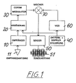
- ein Blockschaltbild der zur Durchführung einer ersten Ausführungsform des erfindungsgemäßen Verfahrens erforderlichen Komponenten eines Satellitentransponders für Übertragung von digitalen Hörfunksignalen nach dem EUREKA 147-DAB-Standard;
- Fig. 2
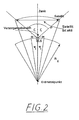
- eine schematische Darstellung des Versorgungsgebietes eines Rundfunksatelliten mit erdnaher Umlaufbahn;
- Fig. 3
- eine schematische Ansicht der Umlaufbahn von sechs Rundfunksatelliten mit erdnaher Umlaufbahn;
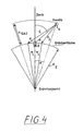
- Fig. 4
- eine schematische Ansicht ähnlich wie in Fig. 2 zur Veranschaulichung bestimmter geometrischer Beziehungen;
- Fig. 5
- eine vereinfachte Darstellung zur Veranschaulichung der Dopplerverschiebung, der Dopplerverschiebungsgeschwindigkeit und des Differenz-Dopplereffektes bei einer Relativbewegung zwischen dem Bezugspunkt mit der Uplink-Station und dem Satelliten;
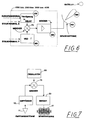
- Fig. 6
- ein Blockschaltbild einer Sendeeinrichtung bei einer alternativen Ausführungsform des erfindungsgemäßen Verfahrens;
- Fig. 7
- ein Blockschaltbild eines herkömmlichen Satellitentransponders, wie er bei der alternativen Ausführungsform des erfindungsgemäßen Verfahrens verwendet werden kann;
- Fig. 8
- ein Blockschaltbild einer Bodenstelle mit mehreren Sendeeinrichtungen gemäß Fig. 6, und
- Fig. 9
- eine schematische Darstellung für die Signalwege eines zentral in die Bodenstelle nach Fig. 8 eingespeisten Rundfunksignals.
- Fig. 1
- a block diagram of the components of a satellite transponder required for carrying out a first embodiment of the method according to the invention for transmission of digital radio signals according to the EUREKA 147-DAB standard;
- Fig. 2
- a schematic representation of the coverage area of a broadcast satellite with near-Earth orbit;
- Fig. 3
- a schematic view of the orbit of six broadcast satellites with near-Earth orbit;
- Fig. 4
- a schematic view similar to Figure 2 to illustrate certain geometric relationships.
- Fig. 5
- a simplified representation to illustrate the Doppler shift, the Doppler shift speed and the differential Doppler effect with a relative movement between the reference point with the uplink station and the satellite;
- Fig. 6
- a block diagram of a transmission device in an alternative embodiment of the method according to the invention;
- Fig. 7
- a block diagram of a conventional satellite transponder, as in the alternative embodiment of the method according to the invention can be used;
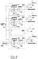
- Fig. 8
- 6 shows a block diagram of a ground station with several transmission devices according to FIG. 6, and
- Fig. 9
- a schematic representation of the signal paths of a radio signal fed centrally into the ground station according to FIG. 8.
Das erfindungsgemäß vorgeschlagene System teilt Satelliten mit erdnahen und mittleren Umlaufbahnen zwischen verschiedenen Rundfunkveranstaltern auf. Jeder Satellit ist bei dem Satellitentransponder gemäß Fig. 1 mit Empfängern 10 ausgerüstet, um über eine Empfangsantenne 11 den DAB-Übertragungsmultiplex von den Uplink-Stationen oder von einem anderen Satelliten, z.B. Fernmeldesatelliten, zu empfangen (Fig. 1). Über eine Verzögerungsleitung 20 wird jeder empfangene DAB-Übertragungsmultiplex einem COFDM-Modulator 30 zugeführt, wobei die Verzögerungsleitung 20 von einer Entfernungs- und Doppler-Steuerung 40 gesteuert wird. Die Verzögerungsleitung 20 kompensiert die Gesamtlaufzeit des DAB-Signals, welches sich zusammensetzt aus der Laufzeit zwischen Sendestelle und Empfänger 10 im Satelliten sowie der Laufzeit zwischen einem Sender 50 im Satelliten und einem Empfänger an einem definierten Bezugspunkt im Versorgungsgebiet. Die Steuerung 40, welche die Verzögerungsleitung 20 steuert, erfaßt daher die Entfernungen zwischen Uplink-Station (Sendestelle) und Satellit sowie zwischen Satellit und einem definierten Bezugspunkt im Versorgungsgebiet, um hieraus die gesamte Signallaufzeit des DAB-Signals zu berechnen. Die Steuerung 40 steuert ferner einen variablen Oszillator 60 (VCO), um die Doppler-Verschiebung bezüglich des Ortes der Uplink-Station zu kompensieren. Die Erfassung der Entfernungen und der Entfernungsgeschwindigkeiten erfolgt durch Signalverarbeitung an Bord des Satelliten. Das COFDM-modulierte DAB-Signal am Ausgang des COFDM-Modulators 30 wird mit der Ausgangsfrequenz des variablen Oszillators 60 in einem Mischer 70 gemischt, wodurch die Mittenfrequenz der COFDM-modulierten DAB-Signale von der nachgeführten Ausgangsfrequenz des steuerbaren Oszillators 60 bestimmt wird. Über den Sender 50 und eine Sendeantenne 51 überträgt der Satellit das Ausgangssignal des Mischers 70 zu den Empfängern im vorgesehenen Versorgungsgebiet, wobei im Sender 50 die COFDM-modulierten DAB-Signale verstärkt werden. Das auf diese Weise abgestrahlte DAB-Rundfunksignal wird von den Teilnehmern in dem Versorgungsbegiet empfangen, welches sich unter dem Satelliten befindet. Der Einfallswinkel bezogen auf das Satelliten-Koordinatensystem und die räumliche Entfernung zum Bezugspunkt wird an Bord des Satelliten laufend gemessen und analysiert, ebenso wie die HF-Frequenzabweichung des Uplink-Signals aufgrund des Doppler-Effektes. Falls der Einfallswinkel des ankommenden Uplink-Signals einen vorgegebenen Grenzwert von beispielsweise 20° überschreitet, wird der im Satelliten befindliche Sender 50 eingeschaltet und das COFDM-Signal wird in Richtung der Quelle des ankommenden Uplink-Signals gesendet, wie aus Fig. 2 ersichtlich ist. Die an Bord des Satelliten gemessene Doppler-Abweichung des empfangenen Uplink-Signals wird ausgewertet, um die Mittenfrequenz des ausgesendeten Signals nachzuführen. Die Mittenfrequenz des Satellitensignals wird mittels des variablen Oszillators 60 auf einen solchen Wert eingestellt, welcher die auftretende Doppler-Abweichung am Ort der Uplink-Station exakt auf Null kompensiert.The system proposed according to the invention divides satellites with near-earth and medium orbits between different broadcasters. In the satellite transponder according to FIG. 1, each satellite is equipped with
Die Verzögerungszeit wird durch Auswertung der Entfernungsinformation gesteuert, welche die Summe der Entfernung zwischen dem Ort des Satelliten und dem Bezugspunkt im Versorgungsgebiet sowie der Entfernung zwischen dem Ort des Satelliten und dem Ort der Uplink-Station ist. Diese gesamte Signallaufzeit des DAB-Signals wird während des aktiven Teils der Satellitenbahn konstant gehalten. Gegebenenfalls wird der an Bord des Satelliten befindliche Sender 50 ausgeschaltet, wenn der Einfallswinkel bezogen auf das Satellitenkoordinatensystem einen bestimmten Grenzwert unterschreitet.The delay time is controlled by evaluating the distance information, which is the sum of the distance between the location of the satellite and the reference point in the coverage area and the distance between the location of the satellite and the location of the uplink station. This total signal transit time of the DAB signal is kept constant during the active part of the satellite orbit. Optionally, the
Aus der schematischen Darstellung nach Fig. 2 ist ersichtlich, wie der Rundfunksatelliten-Transponder innerhalb eines Kegels betrieben bzw. aktiviert wird, welcher durch den Zenit-Entfernungswinkel ζ an der Uplink-Station ULS definiert wird. Der Ort der Uplink-Station stellt das Zentrum des Versorgungsbereiches dar, welcher durch die Winkelsektoren -φ1 und +φ1 bezogen auf den Erdmittelpunkt, bestimmt wird.2 shows how the broadcast satellite transponder is operated or activated within a cone, which one is defined by the zenith distance angle ζ at the uplink station ULS. The location of the uplink station represents the center of the coverage area, which is determined by the angle sectors -φ 1 and + φ 1 in relation to the center of the earth.
Die Dopplerkompensation, die Steuerung der Verzögerungszeit und die Einschalt-Ausschaltbedingungen sind geeignet, weiche Signalübergänge (vgl. Fig. 3) von dem einen Satelliten zu einem oder zu mehreren anderen Satelliten zu gewährleisten. Wie noch erläutert werden soll, können zwei oder mehrere Satelliten gleichzeitig betrieben werden, ohne daß eine DAB-Symbol-Interferenz oder inakzeptable Orthogonalitäts-Verletzungen des EUREKA 147-DAB-Signaltyps innerhalb eines Versorgungsbereichs auftreten.The Doppler compensation, the control of the delay time and the switch-on-switch-off conditions are suitable for ensuring smooth signal transitions (cf. FIG. 3) from one satellite to one or more other satellites. As will be explained, two or more satellites can be operated simultaneously without DAB symbol interference or unacceptable orthogonality violations of the EUREKA 147 DAB signal type within a coverage area.
Die Uplink-Stationen verfügen über rotationssymetrische Richtantennen mit einer maximalen Verstärkung in vertikaler Richtung. Die Bündelung der Antennen wird auf den festen Winkel justiert, innerhalb welchem der Satellit aktiv ist. Zur Gewinnung von Informationen über Entfernung, Entfernungsgeschwindigkeit und Einfallswinkel bezogen auf das Satelliten-Koordinatensystem an Bord des Satelliten lassen sich innerhalb des DAB-Multiplex geeignete Zusatzsignale übertragen. Die Uplink-Stationen am Erdboden können ohne Beschränkung der Anwendbarkeit des Verfahrens durch Bezugspunkte im Versorgungsgebiet und Uplink-Stationen in Erdumlaufbahnen ersetzt werden.The uplink stations have rotationally symmetrical directional antennas with a maximum gain in the vertical direction. The bundling of the antennas is adjusted to the fixed angle within which the satellite is active. Suitable additional signals can be transmitted within the DAB multiplex to obtain information about distance, distance speed and angle of incidence in relation to the satellite coordinate system on board the satellite. The uplink stations on the ground can be replaced by reference points in the coverage area and uplink stations in earth orbits without restricting the applicability of the method.
Die Bahndaten des Satellitensystems werden in Abhängigkeit von den jeweiligen Anforderungen hinsichtiich der Leistung an den Versorgungsrändern, der Verfügbarkeit der Übertragungsfrequenzen und den Toleranzen des örtlichen Elevationswinkelbereiches gewählt. Es gibt keine Einschränkungen bezüglich der Inklination, der Exzentrizität, der Umlaufzeit, der Lage des aufsteigenden Knotens oder der Lage des Perigäums. In Abhängigheit der Höhe über Grund ändert sich die Anzahl der für eine weltweite, kontinuierliche Versorgung erforderlichen Satelliten in einem Bereich zwischen 10 und 100. Bei dem Beispiel nach Fig. 3 sind sechs Rundfunksatelliten S1 bis S6 vorgesehen, wobei die aktiven Zenitwinkelzonen von drei Uplink-Stationen mit ULS I, ULS II und ULS III auf der Erdoberfläche angegeben sind. Wenn sich der Satellit S1 der Uplink-Station ULS I nähert, wird er aktiviert. Der Satellit S2 ist noch aktiv und trägt zur Rundfunkversorgung im Bereich der Uplink-Station I bei. Der Satellit S3 ist aktiv und versorgt den Bereich der Uplink-Station II, wohingegen der Satellit S4 gerade den Aktivierungskegel der Uplink-Station II verläßt und inaktiv wird. Der Versorgungsbereich der Uplink-Station III wird von den Satelliten S5 und S6 gleichzeitig versorgt. An einer Stelle einer Uplink-Station am Boden kann ein anderer Satellit, z.B. Fernmeldesatellit, treten, der das Signal dem Rundfunksatelliten zuführt.The path data of the satellite system are selected depending on the respective requirements with regard to the performance at the supply edges, the availability of the transmission frequencies and the tolerances of the local elevation angle range. There are no restrictions on inclination, eccentricity, orbital period, the location of the ascending node or the location of the perigee. Depending on the height above ground, the number of satellites required for worldwide, continuous coverage changes in a range between 10 and 100. In the example according to FIG. 3, six radio satellites are S1 to S6 provided, the active zenith angle zones of three uplink stations with ULS I, ULS II and ULS III being indicated on the earth's surface. When satellite S1 approaches ULS I uplink station, it is activated. The satellite S2 is still active and contributes to the radio coverage in the area of the uplink station I. Satellite S3 is active and supplies the area of uplink station II, whereas satellite S4 just leaves the activation cone of uplink station II and becomes inactive. The coverage area of the uplink station III is served by the satellites S5 and S6 simultaneously. Another satellite, for example a telecommunications satellite, can appear at one point of an uplink station on the ground and feed the signal to the broadcasting satellite.
Zur Vereinfachung soll für die nachfolgenden Erläuterungen angenommen werden, daß die Orbitalbewegung des Satelliten kreisförmig ist. Atmosphärische oder ionosphärische Ausbreitungseffekte bleiben unberücksichtigt, wenn die Verzögerungszeiten der DAB-Symbole, der Doppler-Effekt oder die Leistung an den Versorgungsrändern berechnet werden. Die Form der Erde wird als sphärisch angenommen, wobei Störungen auf Grund von Abflachungen der Erde und der Erdrotation vernachlässigt werden. Auf spezielle geographische Bereiche wird vorliegend nicht eingegangen. Es wird ferner angenommen, daß DAB-Rundfunksatelliten zur Durchführung der Signalübergabe ein- und ausgeschaltet werden können und zwar in Abhängigkeit von dem auftretenden Elevationswinkel im Zentrum des Versorgungsbereiches. Das Satelliten-Sendesystem kann hinsichtlich der HF-Mittenfrequenz (zur Kompensation von Doppler-Effekten) gesteuert werden und verfügt über Möglichkeiten zur Laufzeitverzögerung des empfangenen Uplink-Signals sowie zur Kompensation der sich ändernden Entfernungen bzw. Signallaufzeiten.For the sake of simplicity, the following explanations assume that the orbital movement of the satellite is circular. Atmospheric or ionospheric propagation effects are not taken into account when calculating the delay times of the DAB symbols, the Doppler effect or the power at the supply edges. The shape of the earth is assumed to be spherical, with disturbances due to flattening of the earth and the earth's rotation being neglected. Special geographic areas are not discussed here. It is also assumed that DAB broadcasting satellites can be switched on and off to carry out the signal transfer, depending on the elevation angle occurring in the center of the coverage area. The satellite transmission system can be controlled with regard to the HF center frequency (to compensate for Doppler effects) and has options for delaying the delay of the received uplink signal and for compensating for the changing distances or signal delays.
Von den Uplink-Stationen wird angenommen, daß sie kontinuierlich arbeiten. Sie haben keine steuerbaren Antennen, so daß keine Satelliten-Verfolgung erfolgt. Die Signalübergabe zwischen den einzelnen Satelliten wird von der Uplink-Station nicht unmittelbar unterstützt; vielmehr wird der Übergabevorgang vollständig durch die Satelliten im Orbit gesteuert.The uplink stations are assumed to operate continuously. They have no controllable antennas, so there is no satellite tracking. The uplink station does not directly support the signal transfer between the individual satellites; rather, the transfer process is completely controlled by the satellites in orbit.
Im Folgenden sollen die Systemanforderungen aufgrund des Schutzzeit-Intervalls des EUREKA 147 DAB-Signaltyps erörtert werden.The system requirements based on the guard time interval of the EUREKA 147 DAB signal type are discussed below.
Falls ein von Symbol-Interferenzen freier Empfang erforderlich ist, darf der Zeitunterschied bis zum Eintreffen eines COFDM-Symbols, welches von zwei getrennten Signalquellen gleichzeitig gesendet wird, das sogenannte Schutzzeitintervall am Empfangsort nicht überschreiten. Im Falle von Satelliten als Signalquellen hat dieses Schutzzeitintervall Auswirkungen auf die Größe des Versorgungsbereiches. Zum Verständnis hierfür sind in der schematischen Darstellung nach Fig. 4 die verschiedenen Variablen angegeben, wobei mit ULS die Uplink-Station und mit S der Rundfunksatellit bezeichnet sind. Die Lageverhältnisse sind innerhalb der Orbitalebene des Satelliten S dargestellt. Dabei wird angenommen, daß der Satellit S die Uplink-Station ULS in Zenitrichtung überquert, was den schlimmsten Fall darstellt.If a reception free of symbol interference is required, the time difference until the arrival of a COFDM symbol, which is sent by two separate signal sources simultaneously, must not exceed the so-called protection time interval at the receiving location. In the case of satellites as signal sources, this guard time interval affects the size of the coverage area. To the The various variables are shown in the schematic representation according to FIG. 4, ULS denoting the uplink station and S denoting the broadcasting satellite. The positional relationships are shown within the orbital plane of the satellite S. It is assumed that the satellite S crosses the uplink station ULS in the zenith direction, which is the worst case.
Das Profil der in Fig. 4 dargestellten Erdoberfläche unterhalb des Satelliten S innerhalb der Orbitalebene ist als Kreisbogen wiedergegeben. Der Ursprung des Koordinatensystems ist der Erdmittelpunkt. Die Höhe des Satelliten über Grund ist mit hSAT, der Erdradius mit RE angegeben. Die Uplink-Station besitzt die Polarkoordinaten 0,RE. Gegenüber dem über der Uplink-Station aufgetragenen Zenit besitzt der Satellit den Zenitwinkel ζ, so daß die Position des Satelliten durch die Polarkoordinaten φ, RE+hSAT gegeben sind. Ein Rundfunkversorgungsbereich wird definiert durch eine Segmentzone um die Uplink-Station ULS, welche gegeben ist durch den geozentrischen Polarwinkel φ1. Wird die Entfernung zwischen der Uplink-Station ULS und dem Satelliten S mit p und die Entfernungen zwischen den linken und rechten Rändern des Versorgungsgebietes zum Satelliten p1 und p2 bezeichnet, dann gilt:
Die Differenz![]()
![]()
![]()
![]()
![]()
![]()
Als Ergebnis erhält man eine Gleichung, welche das Winkelmaß des Versorgungsbereiches als Funktion des Zenitwinkels des Satelliten bezogen auf den Ort der Uplink-Station, der Entfernung des Satelliten vom Erdmittelpunkt und der Differenz der Weglängen zwischen dem Satelliten S und den Rändern des Versorgungsgebietes darstellt:![]()
![]()
![]()
![]()
Falls der Unterschied der beiden Wegstrecken p - p1 bzw. p - p2 die entsprechende Signallaufzeit um nicht mehr als die Hälfte des Schutzintervalls ![]()
![]()
![]()
![]()
Die maximale Verzögerungsdauer tritt auf, wenn der Satellit S die Uplink-Station ULS senkrecht (also im Zenit) überstreicht.The maximum delay period occurs when the satellite S sweeps vertically (ie at the zenith) over the uplink station ULS.
Der Durchmesser des möglichen Versorgungsbereichs als Funktion des Zenitwinkelkegels, des Schutzzeitintervalls und der Orbithöhe des Satelliten ergibt sich aus Tabelle 1.
Aus Tabelle 1 ist ersichtlich, daß die Größe des Versorgungsbereichs von der Größe des Zenitwinkelkegels abhängt. Falls der Kegel eng ist, vergrößert sich die Größe des Versorgungsbereichs. Indessen wird der Teil der Flugbahn, innerhalb welchem der Satellit aktiv betrieben werden kann, entsprechend verringert. Aus diesem Grund muß ein Kompromiß zwischen der Größe des Versorgungsbereiches, der Anzahl von Satelliten im Orbit und dem minimalen Elevationswinkel getroffen werden.It can be seen from Table 1 that the size of the coverage area depends on the size of the zenith angle cone. If the cone is narrow, the size of the coverage area increases. In the meantime, the part of the trajectory within which the satellite can be actively operated is reduced accordingly. For this reason, a compromise must be made between the size of the coverage area, the number of satellites in orbit and the minimum elevation angle.
Im Folgenden soll nunmehr der Einfluß der Doppler-Verschiebung abgeschätzt werden. Die Geschwindigkeit eines Satelliten relativ zum Boden hängt von den Bahnparametern ab. Zur Grobabschätzung des Einflusses der Doppler-Verschiebung auf die Verschlechterung des empfangenen EUREKA 147 DAB-Signals können einige vereinfachende Annahmen getroffen werden. Dabei ist es ausreichend, wenn die Überlegungen auf Kreisbahnen beschränkt werden.The influence of the Doppler shift will now be estimated in the following. The speed of a satellite relative to the ground depends on the orbit parameters. To make a rough estimate of the influence of the Doppler shift on the deterioration of the received EUREKA 147 DAB signal, some simplifying assumptions can be made. It is sufficient if the considerations are limited to circular orbits.
Aufgrund der maximalen Größe des Versorgungsbereiches (Dsa < 250 km), der steilen Elevationswinkel ( ζ < 20°) und der angenommenen minimalen Höhe des Satelliten über Grund (hsat > 800 km) ist ferner die Näherung der sphärischen Oberflächen durch ebene Oberflächen bzw. der Kreisbogen durch gerade Linien gerechtfertigt. Mit diesen Vereinfachungen erhält man aus Fig. 5 folgende Beziehung:![]()
- vsat
- die Geschwindigkeit des Satelliten,
- b
- die x-Koordinate der Grenze des Versorgungsbereiches,
- p(t)
- die Entfernung des Satelliten bezüglich des Zentrums des Versorgungsbereiches, und
- t=0
- die Zeit beim Überqueren des durch ζ gegebenen Zenitwinkelkegels durch den Satelliten
- v sat
- the speed of the satellite,
- b
- the x coordinate of the border of the supply area,
- p (t)
- the distance of the satellite from the center of the coverage area, and
- t = 0
- the time when the satellite crosses the zenith cone given by ζ
Die Satellitengeschwindigkeit errechnet sich dann zu:![]()
![]()
![]()
![]()
Die zeitliche Ableitung der Gleichung 8 liefert die Entfernungsgeschwindigkeit:![]()
![]()
![]()
![]()
![]()
![]()
In Tabelle 2 ist die auftretende Doppler-Verschiebung angegeben, wie sie im Zentrum des Versorgungsbereichs ohne Kompensation an Bord des Satelliten auftritt. Tabelle 3 zeigt die verbleibende Differenzverschiebung an den Rändern des Versorgungsbereichs unter der Annahme, daß die Doppler-Verschiebung bezüglich des Zentrums des Versorgungsbereichs an Bord des Satelliten kompensiert wird.
In Tabelle 2 ergibt sich der auftretende maximale Absolutwert der Doppler-Verschiebung ![]()
![]()
![]()
![]()
![]()
![]()
![]()
![]()
Tabelle 3 zeigt die auftretenden minimalen und maximalen Werte der Doppler-Verschiebung im Falle einer Vor-Kompensation an Bord des Satelliten. Die angegebenen Werte stellen den schlechtesten Fall dar, wie er sich für einen Beobachter an den Versorgungsrändern ergibt. Die erläuterte Kompensationsstrategie beseitigt die auftretende Doppler-Verschiebung im Zentrum des Versorgungsbereichs. In Tabelle 3 sind die gleichen Parameter wie in Tabelle 2 angegeben. Die Abkürzungen haben folgende Bedeutung:
Die Doppler-Verschiebung bei einer HF-Mittenfrequenz von 150 MHz betragt ein Zehntel der in Tabelle 3 angegebenen Werte.The Doppler shift at an RF center frequency of 150 MHz is one tenth of the values given in Table 3.
Wie man aus Tabelle 2 erkennt, ist die Doppler-Verschiebung des Satellitensignals am Boden ganz offensichtlich ohne weitere Maßnahmen nicht tolerierbar, da sie ernsthafte Verletzungen der Orthogonalität des COFDM-Signals für alle DAB-Moden verursacht. Demgegenüber funktioniert die Doppler-Kompensation nach der vorliegenden Erfindung hinreichend gut, wie man aus den Ergebnissen für den schlimmsten Fall gemäß Tabelle 3 ersieht. Es zeigt sich, daß an sämtlichen Orten innerhalb des Versorgungsbereichs die auftretende Gesamtfrequenzänderung während eines Satellitendurchlaufs maximal etwa 3 % der beobachteten Werte im Vergleich zu einer fehlenden Kompensation beträgt. Wenn der HF-Träger unterhalb 150 MHz liegt, tritt für sämtliche DAB-Moden keine wesentliche Verschlechterung der Empfangsverhältnisse aufgrund von Orthogonalitätsverletzungen auf. Im Falle der Verwendung des L-Bandes als HF-Träger ist der DAB-Mode # 1 für Satelliten mit erdnahen Umlaufbahnen nicht geeignet; dieser Mode ist aufgrund der Mehrwege-Ausbreitung am Boden ohnehin nicht für eine L-Band-Übertragung geeignet.As can be seen from Table 2, the Doppler shift of the satellite signal on the ground is obviously intolerable without further measures, since it causes serious violations of the orthogonality of the COFDM signal for all DAB modes. In contrast, the Doppler compensation according to the present invention works sufficiently well, as can be seen from the worst case results in Table 3. It can be seen that at all locations within the coverage area, the total frequency change occurring during a satellite pass is a maximum of approximately 3% of the observed values compared to a lack of compensation. If the RF carrier is below 150 MHz, there is no significant deterioration in the reception conditions due to orthogonality violations for all DAB modes. If the L-band is used as an HF carrier,
Es versteht sich, daß die absolute Frequenz-Abweichung von der Mittenfrequenz des nominellen DAB-Kanals an einem speziellen Ort von der Geometrie der Satellitenbahn relativ zu dem Versorgungsbereich abhängt. Wenn sich der Empfänger an der Grenze des Versorgungsbereichs befindet, welche ganz in der Nähe der Stelle liegt, wo der Satellit aktiv wird, ist die Frequenz-Abweichung positiv; falls der Empfänger an der gegenüberliegenden Versorgungsgrenze liegt, ist die Frequenz-Abweichung negativ. Die relative Abweichung von der exakten Lage der HF-Mittenfrequenz ist in allen Fällen sehr gering im Vergleich zum nicht-kompensierten Fall.It is understood that the absolute frequency deviation from the center frequency of the nominal DAB channel at a particular location depends on the geometry of the satellite orbit relative to the coverage area. If the receiver is on the border of the coverage area, which is very close to the place where the satellite is active, the frequency deviation is positive; if the receiver is on the opposite supply limit, the frequency deviation is negative. The relative deviation from the exact position of the HF center frequency is very small in all cases compared to the non-compensated case.
Die Leistungsbilanz von DAB-Satelliten mit erdnahen und mittleren Umlaufbahnen läßt sich mit Hilfe folgender Gleichung abschätzen:![]()
- P
- die Leistung des Senders [dBW],
- fRF
- die HF-Trägerfrequenz [GHz],
- p
- die Länge des Signalweges [km],
- La
- die atmosphärische Dämpfung [dB],
- GT
- die Verstärkung der Sendeantenne an Bord des Satelliten [dB],
- GR
- die Verstärkung der Empfangsantenne an Bord des Satelliten [dB],
- T
- die Temperatur des Empfangssystems an Bord des Satelliten [K],
- B
- die Signalbandbreite [Hz]
- P
- the power of the transmitter [dBW],
- f RF
- the RF carrier frequency [GHz],
- p
- the length of the signal path [km],
- L a
- atmospheric attenuation [dB],
- G T
- the amplification of the transmitting antenna on board the satellite [dB],
- G R
- the gain of the receiving antenna on board the satellite [dB],
- T
- the temperature of the receiving system on board the satellite [K],
- B
- the signal bandwidth [Hz]
Für die Bauteile des Rundfunksystems müssen einige Annahmen bezüglich der Breite Öffnungskeule der Sendeantenne 51 (Fig. 1), der Eigenschaften des Rundfunkempfängers und des Antennen-Wirkungsgrades gemacht werden. Zur Vereinfachung wird davon ausgegangen, daß die Halbwertsbreite der Sendeantenne 51 an das Versorgungsbereich angepaßt ist. Dies ist aus Frequenzgründen günstig, da die räumliche Wiederholung der Nachbarkanalfrequenzen optimal ist, wenn der Spill-Over minimiert wird. Für die Sendeantenne wird ein Wirkungsgrad von 0,5 angenommen. In der Praxis bedeutet dies, daß der Satellit mit einer phasengeschalteten Array-Antenne ausgerüstet ist, wobei die Mitte des Antennenstrahls auf die Uplink-Station bzw. den Bezugspunkt im Versorgungsgebiet zeigt. Da die Richtung auf diesen, Referenzort an Bord des Satelliten gemessen wird oder berechnet werden kann, ist diese Annahme realistisch.For the components of the radio system, some assumptions have to be made regarding the width of the opening lobe of the transmitting antenna 51 (FIG. 1), the properties of the radio receiver and the antenna efficiency. For the sake of simplicity, it is assumed that the half-width of the
Mit den vorstehenden Annahmen kommt man zu folgenden Ergebnissen:
In der vorstehenden Tabelle geben die Indizes die Bahnhöhe an, wobei die Temperatur des Empfangssystems 400°K, die Bandbreite 1,536MHz, die atmosphärische Dämpfung La 1dB und die Sendeleistung P 100W betragen.In the table above, the indices indicate the web height, the temperature of the receiving system being 400 ° K, the bandwidth 1.536 MHz, the atmospheric attenuation L a 1dB and the transmission power P 100W.
Für die Rausch-Leistungsverhältnisse ergeben sich folgende Werte:
Das vorstehende Ergebnis zeigt, daß Dämpfungseffekte aufgrund von Sperr- und Belaubungsdämpfung mit Hilfe hoher Leistungsflußdichten beseitigt werden können. Die Verwendung von VHF-Frequenzen ist optimal bezüglich Antennenöffnung, Leistungsbilanz und Größe des Versorgungsbereichs.The above result shows that damping effects due to barrier and leaf damping can be eliminated with the aid of high power flux densities. The use of VHF frequencies is optimal in terms of antenna opening, power balance and size of the coverage area.
Was die Anzahl der für das erfindungsgemäße System erforderlichen Satelliten anbelangt, so ist davon ausgegangen, daß eine kontinuierliche Versorgung erfolgt. Hieraus ergibt sich der nutzbare (aktive) Bogenabschnitt als Teil einer vollständigen Satellitenbahn. Ferner läßt sich das zugeordnete Zeitintervall errechnen, in welchem sich der Satellit über der unteren Elevationswinkelgrenze befindet. Dieses Zeitintervall ist zumindest zweimal täglich für die Versorgung innerhalb des betrachteten Versorgungsbereichs verfügbar, da sowohl der bezüglich der Äquatorebene aufsteigende als auch absteigende Teil der Satellitenbahn in Betracht zu ziehen ist. Die erforderliche maximale Anzahl NSAT von Satelliten ergibt sich dann durch Teilung von 24 Stunden (1 Tag) durch die Dauer des Zeitintervalls, in welchem ein Satellit bezüglich eines spezifischen Versorgungsbereiches täglich aktiv ist. Die Ergebnisse sind in Tabelle 5 wiedergegeben. Dabei hängt NSAT nicht von der Größe des Versorgungsbereichs ab.
Die Erfindung läßt sich wie folgt zusammenfassen:The invention can be summarized as follows:
Ein Satellitensystem mit erdnahen oder mittleren Umlaufbahnen stellt ein geeignetes Rundfunkversorgungssystem dar, wenn als Übertragungsstandard der EUREKA 147-DAB-Standard gewählt wird. Die Eigenschaften eines dementsprechend bemessenen Satellitensystem mit erdnahen oder mittleren Umlaufbahnen sind:
- Weiche Signalübergabe zwischen den einzelnen Satelliten;
- einfache Hardware-Ausrüstung der Uplink-Stationen ohne Unterstützung für die Signalübergabe und ohne Satellitenverfolgung mittels schwenkbarer Antennen;
- ausgezeichnete Leistungsbilanz an den Versorgungsrändern;
- hohe Elevationswinkel innerhalb der Versorgungsbereiche;
- hohe Zuverlässigkeit aufgrund gleichzeitiger Übertragung durch mehrere Satelliten;
- weltweite Verfügbarkeit.
- Soft signal transmission between the individual satellites;
- simple hardware equipment of the uplink stations without support for signal transmission and without satellite tracking by means of swiveling antennas;
- excellent current account at the supply margins;
- high elevation angles within the coverage areas;
- high reliability due to simultaneous transmission by several satellites;
- worldwide availability.
Die Bahnparameter sind nicht auf geosynchrone oder geostationäre Bahnen beschränkt. Vielmehr ist das vorgeschlagene Rundfunkversorgungssystem weltweit verfügbar. Verschiedene Rundfunkveranstalter können das vorgeschlagene Rundfunkversorgungssystem durch Installation kostengünstiger Erdstationen (Uplink-Stationen) miteinander teilen, welche lediglich das DAB-Multiplex-Übertragungssignal in vertikaler Richtung abzustrahlen brauchen. Weder eine Satellitenverfolgung noch eine Bodensteuerung für die Signalübergabe zwischen den Satelliten ist in den Uplink-Stationen erforderlich. Die erzielbaren Versorgungsbereiche sind ausreichend groß für eine regionale und nationale Rundfunkversorgung.The path parameters are not limited to geosynchronous or geostationary paths. Rather, the proposed broadcasting system is available worldwide. Various broadcasters can share the proposed radio supply system with one another by installing inexpensive earth stations (uplink stations) which only need to transmit the DAB multiplex transmission signal in the vertical direction. Neither satellite tracking nor ground control for signal transfer between the satellites is required in the uplink stations. The coverage areas that can be achieved are sufficiently large for regional and national broadcasting coverage.
Bei einer an Hand der Fign. 6 bis 9 dargestellten alternativen Ausführungsform des erfindungsgemäßen Verfahrens können Maßnahmen in einer Bodenstation (Fig. 8) getroffen werden, um die Gesamtlaufzeit des Signals konstant zu halten. Auf diese Weise läßt sich die Verzögerungsleitung 20 (Fig. 1) im Satelliten vermeiden, die von einer Steuereinrichtung 40 (Fig. 1) derart gesteuert wird, daß die Gesamtlaufzeit des Rundfunksignals von der Sendestelle am Boden zum Satelliten und vom Satelliten zurück zu einem Bezugspunkt im Versorgungsgebiet konstant gehalten wird. Bei der Alternative nach Fign. 6 bis 9 sind zunächst mindestens zwei identisch aufgebaute Sendeeinrichtungen erforderlich, um mindestens zwei Satelliten des Rundfunksignals zubringen zu können; andernfalls wäre ein unterbrechungsfreier Rundfunkbetrieb nicht möglich. Der technische Aufbau einer der benötigten Sendeeinrichtungen ist in Fig. 6 dargestellt.In the case of a 6 to 9 shown alternative embodiment of the method according to the invention, measures can be taken in a ground station (FIG. 8) in order to keep the total running time of the signal constant. In this way, the delay line 20 (Fig. 1) in the satellite can be avoided, which is controlled by a control device 40 (Fig. 1) in such a way that the total duration of the radio signal from the transmitting point on the ground to the satellite and from the satellite back to a reference point is kept constant in the supply area. In the alternative according to FIGS. 6 to 9, at least two identically constructed transmission devices are initially required in order to be able to bring at least two satellites of the radio signal; otherwise uninterrupted broadcasting would not be possible. The technical structure of one of the required transmission devices is shown in FIG. 6.
Das COFDM-Rundfunksignal wird mit einer steuerbaren Verzögungseinrichtung 100 nach Maßgabe des Steuersignals E verzögert. Der Ausgang der Verzögerungseinrichtung 100 ist mit dem ersten Eingang eines Mischers 70 verbunden, dessen zweiter Eingang von dem Oszillator 200 mit variabler Frequenz f gespeist wird. Die Frequenz des Oszillators 200 wird von einem Steuersignal F gesteuert. Der Ausgang des Mischers 70 ist mit dem Eingang des Senders 300 verbunden, der über die Sendeantenne 310 mit gerichteter Antennenkeule 320 dem Satelliten das Rundfunksignal zuführt. Das Steuersignal F steuert den Oszillator 200 so, daß das von dem Satelliten in das Versorgungsgebiet wiederausgestrahlte Signal am Bezugspunkt konstante Frequenz hat. Das Steuersignal E steuert die Verzögerungseinrichtung 100 so, daß die Gesamtzeit, gebildet aus der Laufzeit durch die Verzögerungseinrichtung 100, der Laufzeit von der Bodenstelle zum Satelliten, der Laufzeit durch den Satellitentransponder (Fig. 7) und der Laufzeit vom Satelliten zum Bezugspunkt konstant ist und einem definierten Offset-Wert entspricht. Damit kompensiert das Steuersignal E mittels der Verzögerungseinrichtung 100 die Laufzeitänderungen zwischen der Bodenstelle und dem Satelliten, der infolge seiner Relativbewegung zur Bodenstelle seine Entfernung ändert; das Steuersignal F dient der Steuerung des Oszillators 200, der den Doppler-Effekt der Satellitenbewegung relativ zu einem Bezugspunkt im Versorgungsgebiet kompensiert.The COFDM broadcast signal is delayed with a
Für den Satellitentransponder wird ein in Fig. 7 dargestellter, herkömmlicher Aufbau angenommen. Von dem Aufbau nach Fig. 1 unterscheidet sich der Transpender nach Fig. 7 dadurch, daß im Signalzweig zwischen Empfänger 10 und Mischer 70 die Verzögerung 20 und der COFDM-Modulator 30 fehlen. Ferner wird der Oszillator 60 gemäß Fig. 7 nicht von einer Steuerung 40 gesteuert, sondern läuft frei.A conventional structure shown in FIG. 7 is assumed for the satellite transponder. The transpender according to FIG. 7 differs from the construction according to FIG. 1 in that the delay 20 and the
Der Aufbau der Bodenstelle ist in Fig. 8 gezeigt. Von einem Einspeisepunkt 400 aus, der mit einem Pfeil und der Bezeichnung "Rundfunksignal" eingezeichnet ist, wird in mindestens zwei, ansonsten beliebig viele Sendeeinrichtungen 1000, 2000, 3000 und 4000 gemäß Fig. 6 verzweigt. Von einer gemeinsamen Steuereinrichtung 500 werden die Steuersignale E (für den Laufzeitausgleich der variablen Entfernung zum jeweiligen Satelliten S1, S2 ... Sn) und F (für die Kompensation des Doppelereffekts) erzeugt und an die Sendeeinrichtungen 1000, 2000, 3000, 4000 gegeben.The structure of the ground location is shown in Fig. 8. From an
Die Sendeeinrichtungen 1000 und 2000 sind die Mindestausstattung einer Bodenstelle für die unterbrechungsfreie Versorung. Die Steuereinrichtung 500 erzeugt Steuersignale für die Einstellung der jeweiligen Oszillatorfrequenzen f1, f2 ... fn der Oszillatoren 200, die für die Kompensation des Doppler-Effektes variabel sind, sowie für die Einstellung der Verzögerungseinrichtungen 100, welche die Konstanz und Gleichheit der Laufzeiten aller Satellitenpfade zwischen dem zentralen Einspeisepunkt 400 des Rundfunksignals und dem Bezugspunkt im Versorgungsgebiet herstellen.The
Die Sendeantennen 310a, 310b ... 310n der Bodenstelle gemäß Fig. 8 führen den erdnahen Satelliten S1, S2 ... Sn innerhalb eines vorgegebenen Zenitwinkelbereichs die Rundfunksignale über Richtantennen zu. Die Gesamtlaufzeiten der einzelnen Signalwege zwischen zentralem Einspeisepunkt 400 der Sendeeinrichtungen 1000, 2000 ... 4000, welche sich zusammensetzt aus der Laufzeit durch die jewelige Verzögerungseinrichtung 100a, 100b ... 100n, der Laufzeit von der Bodenstelle zum jeweiligen Satelliten 1, 2 ... n, der Laufzeit durch den Satellitentransponder (Fig. 7) und der Laufzeit vom jeweiligen Satelliten 1, 2 ... n zum Bezugspunkt, wird konstant und für jeden Satelliten 1, 2 ... n gleich groß gehalten. Dieser Sachverhalt ist in Fig. 9 veranschaulicht. Um die Laufzeiten der Rundfunksignale zwischen dem zentralen Einspeisepunkt 400 und dem Bezugspunkt im Versorgungsgebiet für alle Verbindungspfade zwischen der Bodenstelle, den Satelliten S1, S2 ... Sn und den Rückwegen zum Bezugspunkt konstant und gleich groß zu halten, werden die Verzögerungseinrichtungen 100 a, 100b ... 100n durch Steuersignale so nachgeführt, daß die veränderliche Laufzeit aufgrund der Relativbewegung zu den Satelliten S1, S2 ... Sn ausgeglichen wird.8 transmit the radio signals via directional antennas to the satellites S 1 , S 2 ... S n close to the earth within a predetermined zenith angle range. The total running times of the individual signal paths between the
Claims (6)
Das Rundfunksignale wird in der Sendestelle um eine Zeitdauer δτDELAY verzögert, derart, daß die Summe aus dieser Zeitdauer und der gesamten Signallaufzeit cAusbreitung -1 · (p1(t)+p2(t)) des Rundfunksignals einem konstanten Wert τoffset entspricht:
The radio signal is delayed in the transmitting station by a time period δτ DELAY such that the sum of this time period and the total signal propagation time c propagation -1 · (p 1 (t) + p 2 (t)) of the radio signal has a constant value τ offset corresponds to:
Applications Claiming Priority (2)
| Application Number | Priority Date | Filing Date | Title |
|---|---|---|---|
| DE19618142A DE19618142B4 (en) | 1996-05-06 | 1996-05-06 | Method for transmitting COFDM-modulated broadcast signals via a satellite system and satellite transponder for carrying out the method |
| DE19618142 | 1996-05-06 |
Publications (3)
| Publication Number | Publication Date |
|---|---|
| EP0806850A2 true EP0806850A2 (en) | 1997-11-12 |
| EP0806850A3 EP0806850A3 (en) | 1999-11-03 |
| EP0806850B1 EP0806850B1 (en) | 2005-11-02 |
Family
ID=7793479
Family Applications (1)
| Application Number | Title | Priority Date | Filing Date |
|---|---|---|---|
| EP97103914A Expired - Lifetime EP0806850B1 (en) | 1996-05-06 | 1997-03-08 | Method for transmission of COFDM-modulated broadcast signals through a satellite system |
Country Status (3)
| Country | Link |
|---|---|
| EP (1) | EP0806850B1 (en) |
| AT (1) | ATE308833T1 (en) |
| DE (2) | DE19618142B4 (en) |
Family Cites Families (6)
| Publication number | Priority date | Publication date | Assignee | Title |
|---|---|---|---|---|
| US4004098A (en) * | 1973-12-06 | 1977-01-18 | Communications Satellite Corporation (Comsat) | Satellite on-board switching system with satellite-to-satellite link |
| GB9219486D0 (en) * | 1992-09-15 | 1992-10-28 | British Broadcasting Corp | Digital audio broadcasts |
| DE4306590A1 (en) * | 1992-09-21 | 1994-03-24 | Rohde & Schwarz | Digital broadcast network system |
| JPH0738610B2 (en) * | 1993-03-01 | 1995-04-26 | 日本電気株式会社 | Orbiting satellite transmitter |
| US5440562A (en) * | 1993-12-27 | 1995-08-08 | Motorola, Inc. | Communication through a channel having a variable propagation delay |
| GB2293725B (en) * | 1994-07-22 | 1999-02-10 | Int Maritime Satellite Organiz | Satellite communication method and apparatus |
-
1996
- 1996-05-06 DE DE19618142A patent/DE19618142B4/en not_active Expired - Fee Related
-
1997
- 1997-03-08 DE DE59712465T patent/DE59712465D1/en not_active Expired - Lifetime
- 1997-03-08 EP EP97103914A patent/EP0806850B1/en not_active Expired - Lifetime
- 1997-03-08 AT AT97103914T patent/ATE308833T1/en active
Also Published As
| Publication number | Publication date |
|---|---|
| EP0806850B1 (en) | 2005-11-02 |
| DE59712465D1 (en) | 2005-12-08 |
| DE19618142A1 (en) | 1997-11-13 |
| EP0806850A3 (en) | 1999-11-03 |
| DE19618142B4 (en) | 2005-03-17 |
| ATE308833T1 (en) | 2005-11-15 |
Similar Documents
| Publication | Publication Date | Title |
|---|---|---|
| DE69032430T2 (en) | SATELLITE BASED SAME-WAVE CALLING SYSTEM | |
| DE69839238T2 (en) | A method and arrangement for high data rate transmission in a satellite communications network | |
| DE19747065B4 (en) | Method for communication with communication stations, digital beamformer and communication station | |
| DE60021483T2 (en) | METHOD AND DEVICE FOR PRODUCING A BROADBAND SERVICE WITH SATELLITES ON A LOW AND MEDIUM RAIL | |
| DE69229179T2 (en) | BROADCASTING SYSTEMS AND METHODS, WITH TWO CHEAP GEOSTATIONARY SATELLITES | |
| DE60126792T2 (en) | CONSTRUCTION OF A BACK CONNECTION WITH LIMITED PERFORMANCE SENSOR DENSITY FOR MOBILE SATELLITE COMMUNICATION SYSTEM | |
| DE69838272T2 (en) | Method and device for producing broadband communications for mobile users in a satellite network | |
| DE69124664T2 (en) | Satellite transmission system for a call system | |
| DE60218871T2 (en) | METHOD AND DEVICE FOR SEPARATING BETWEEN A MOBILE PLATFORM AND AN EARTH SEGMENT | |
| DE60006564T2 (en) | SWITCHING A RADIO CONNECTION FROM ONE PLANE TO ANOTHER | |
| DE69724379T2 (en) | Multi-beam antenna, method and system for generating cells of a wireless communication network, the multi-beam antenna being arranged on an aircraft | |
| DE69720766T2 (en) | METHOD AND DEVICE FOR BETTER MESSAGE TRANSMISSION | |
| DE60028017T2 (en) | DEVICE AND METHOD FOR RADIO CALL IN A SATELLITE COMMUNICATION ARRANGEMENT WITH USER RANGE | |
| DE19720720A1 (en) | Communication system and method for geosynchronous satellites | |
| DE69605980T2 (en) | Low-flying satellite communication arrangement, station and terminal therefor | |
| DE69121650T2 (en) | Method and device for generating a plurality of frequency-addressable scanning radiation lobes | |
| WO1988004866A1 (en) | Process for data transmission by means of a geo-stationary satellite and at least one sub-satellite | |
| DE69432214T2 (en) | Communication via a channel with a variable delay time | |
| DE60213355T2 (en) | A method and apparatus for identifying which of a plurality of mobile terminals causes interference with one or more satellites adjacent to a target satellite | |
| DE60024733T2 (en) | System for aligning a satellite antenna | |
| DE69230393T2 (en) | Communication arrangement for terminals with satellites in low orbits | |
| DE69330849T2 (en) | Device and method for spectrum recovery | |
| DE69807883T2 (en) | TELECOMMUNICATIONS ARRANGEMENT | |
| DE69230015T2 (en) | Communication system using satellites in low orbit to mobile stations | |
| DE102019117969B3 (en) | Communication device, in particular small and micro-satellites such as CubeSat, system and associated method |
Legal Events
| Date | Code | Title | Description |
|---|---|---|---|
| PUAI | Public reference made under article 153(3) epc to a published international application that has entered the european phase |
Free format text: ORIGINAL CODE: 0009012 |
|
| AK | Designated contracting states |
Kind code of ref document: A2 Designated state(s): AT BE CH DE DK ES FI FR GB GR IE IT LI LU NL PT SE |
|
| AX | Request for extension of the european patent |
Free format text: SI PAYMENT 970402 |
|
| PUAL | Search report despatched |
Free format text: ORIGINAL CODE: 0009013 |
|
| AK | Designated contracting states |
Kind code of ref document: A3 Designated state(s): AT BE CH DE DK ES FI FR GB GR IE IT LI LU NL PT SE |
|
| AX | Request for extension of the european patent |
Free format text: SI PAYMENT 19970402 |
|
| 17P | Request for examination filed |
Effective date: 19991221 |
|
| 17Q | First examination report despatched |
Effective date: 20040405 |
|
| GRAP | Despatch of communication of intention to grant a patent |
Free format text: ORIGINAL CODE: EPIDOSNIGR1 |
|
| GRAS | Grant fee paid |
Free format text: ORIGINAL CODE: EPIDOSNIGR3 |
|
| GRAA | (expected) grant |
Free format text: ORIGINAL CODE: 0009210 |
|
| AK | Designated contracting states |
Kind code of ref document: B1 Designated state(s): AT BE CH DE DK ES FI FR GB GR IE IT LI LU NL PT SE |
|
| AX | Request for extension of the european patent |
Extension state: SI |
|
| PG25 | Lapsed in a contracting state [announced via postgrant information from national office to epo] |
Ref country code: IT Free format text: LAPSE BECAUSE OF FAILURE TO SUBMIT A TRANSLATION OF THE DESCRIPTION OR TO PAY THE FEE WITHIN THE PRE;WARNING: LAPSES OF ITALIAN PATENTS WITH EFFECTIVE DATE BEFORE 2007 MAY HAVE OCCURRED AT ANY TIME BEFORE 2007. THE CORRECT EFFECTIVE DATE MAY BE DIFFERENT FROM THE ONE RECORDED.SCRIBED TIME-LIMIT Effective date: 20051102 Ref country code: IE Free format text: LAPSE BECAUSE OF FAILURE TO SUBMIT A TRANSLATION OF THE DESCRIPTION OR TO PAY THE FEE WITHIN THE PRESCRIBED TIME-LIMIT Effective date: 20051102 Ref country code: GB Free format text: LAPSE BECAUSE OF FAILURE TO SUBMIT A TRANSLATION OF THE DESCRIPTION OR TO PAY THE FEE WITHIN THE PRESCRIBED TIME-LIMIT Effective date: 20051102 Ref country code: FI Free format text: LAPSE BECAUSE OF FAILURE TO SUBMIT A TRANSLATION OF THE DESCRIPTION OR TO PAY THE FEE WITHIN THE PRESCRIBED TIME-LIMIT Effective date: 20051102 |
|
| REG | Reference to a national code |
Ref country code: GB Ref legal event code: FG4D Free format text: NOT ENGLISH |
|
| REG | Reference to a national code |
Ref country code: CH Ref legal event code: EP |
|
| REF | Corresponds to: |
Ref document number: 59712465 Country of ref document: DE Date of ref document: 20051208 Kind code of ref document: P |
|
| PG25 | Lapsed in a contracting state [announced via postgrant information from national office to epo] |
Ref country code: SE Free format text: LAPSE BECAUSE OF FAILURE TO SUBMIT A TRANSLATION OF THE DESCRIPTION OR TO PAY THE FEE WITHIN THE PRESCRIBED TIME-LIMIT Effective date: 20060202 Ref country code: GR Free format text: LAPSE BECAUSE OF FAILURE TO SUBMIT A TRANSLATION OF THE DESCRIPTION OR TO PAY THE FEE WITHIN THE PRESCRIBED TIME-LIMIT Effective date: 20060202 Ref country code: DK Free format text: LAPSE BECAUSE OF FAILURE TO SUBMIT A TRANSLATION OF THE DESCRIPTION OR TO PAY THE FEE WITHIN THE PRESCRIBED TIME-LIMIT Effective date: 20060202 |
|
| PG25 | Lapsed in a contracting state [announced via postgrant information from national office to epo] |
Ref country code: ES Free format text: LAPSE BECAUSE OF FAILURE TO SUBMIT A TRANSLATION OF THE DESCRIPTION OR TO PAY THE FEE WITHIN THE PRESCRIBED TIME-LIMIT Effective date: 20060213 |
|
| REG | Reference to a national code |
Ref country code: CH Ref legal event code: NV Representative=s name: PATENTANWAELTE SCHAAD, BALASS, MENZL & PARTNER AG |
|
| PG25 | Lapsed in a contracting state [announced via postgrant information from national office to epo] |
Ref country code: PT Free format text: LAPSE BECAUSE OF FAILURE TO SUBMIT A TRANSLATION OF THE DESCRIPTION OR TO PAY THE FEE WITHIN THE PRESCRIBED TIME-LIMIT Effective date: 20060403 |
|
| GBV | Gb: ep patent (uk) treated as always having been void in accordance with gb section 77(7)/1977 [no translation filed] |
Effective date: 20051102 |
|
| REG | Reference to a national code |
Ref country code: IE Ref legal event code: FD4D |
|
| ET | Fr: translation filed | ||
| PLBE | No opposition filed within time limit |
Free format text: ORIGINAL CODE: 0009261 |
|
| STAA | Information on the status of an ep patent application or granted ep patent |
Free format text: STATUS: NO OPPOSITION FILED WITHIN TIME LIMIT |
|
| 26N | No opposition filed |
Effective date: 20060803 |
|
| REG | Reference to a national code |
Ref country code: FR Ref legal event code: PLFP Year of fee payment: 19 |
|
| PGFP | Annual fee paid to national office [announced via postgrant information from national office to epo] |
Ref country code: CH Payment date: 20150319 Year of fee payment: 19 Ref country code: DE Payment date: 20150323 Year of fee payment: 19 Ref country code: NL Payment date: 20150319 Year of fee payment: 19 Ref country code: LU Payment date: 20150319 Year of fee payment: 19 |
|
| PGFP | Annual fee paid to national office [announced via postgrant information from national office to epo] |
Ref country code: AT Payment date: 20150323 Year of fee payment: 19 Ref country code: FR Payment date: 20150319 Year of fee payment: 19 |
|
| PGFP | Annual fee paid to national office [announced via postgrant information from national office to epo] |
Ref country code: BE Payment date: 20150318 Year of fee payment: 19 |
|
| PG25 | Lapsed in a contracting state [announced via postgrant information from national office to epo] |
Ref country code: BE Free format text: LAPSE BECAUSE OF NON-PAYMENT OF DUE FEES Effective date: 20160331 |
|
| REG | Reference to a national code |
Ref country code: DE Ref legal event code: R119 Ref document number: 59712465 Country of ref document: DE |
|
| PG25 | Lapsed in a contracting state [announced via postgrant information from national office to epo] |
Ref country code: LU Free format text: LAPSE BECAUSE OF NON-PAYMENT OF DUE FEES Effective date: 20160308 |
|
| REG | Reference to a national code |
Ref country code: CH Ref legal event code: PL |
|
| REG | Reference to a national code |
Ref country code: AT Ref legal event code: MM01 Ref document number: 308833 Country of ref document: AT Kind code of ref document: T Effective date: 20160308 |
|
| REG | Reference to a national code |
Ref country code: NL Ref legal event code: MM Effective date: 20160401 |
|
| REG | Reference to a national code |
Ref country code: FR Ref legal event code: ST Effective date: 20161130 |
|
| PG25 | Lapsed in a contracting state [announced via postgrant information from national office to epo] |
Ref country code: CH Free format text: LAPSE BECAUSE OF NON-PAYMENT OF DUE FEES Effective date: 20160331 Ref country code: FR Free format text: LAPSE BECAUSE OF NON-PAYMENT OF DUE FEES Effective date: 20160331 Ref country code: LI Free format text: LAPSE BECAUSE OF NON-PAYMENT OF DUE FEES Effective date: 20160331 Ref country code: NL Free format text: LAPSE BECAUSE OF NON-PAYMENT OF DUE FEES Effective date: 20160401 Ref country code: DE Free format text: LAPSE BECAUSE OF NON-PAYMENT OF DUE FEES Effective date: 20161001 |
|
| PG25 | Lapsed in a contracting state [announced via postgrant information from national office to epo] |
Ref country code: AT Free format text: LAPSE BECAUSE OF NON-PAYMENT OF DUE FEES Effective date: 20160308 |