EP0806807A2 - Coaxial filter - Google Patents
Coaxial filter Download PDFInfo
- Publication number
- EP0806807A2 EP0806807A2 EP97660053A EP97660053A EP0806807A2 EP 0806807 A2 EP0806807 A2 EP 0806807A2 EP 97660053 A EP97660053 A EP 97660053A EP 97660053 A EP97660053 A EP 97660053A EP 0806807 A2 EP0806807 A2 EP 0806807A2
- Authority
- EP
- European Patent Office
- Prior art keywords
- coaxial resonator
- resonator
- section
- filter
- filter according
- Prior art date
- Legal status (The legal status is an assumption and is not a legal conclusion. Google has not performed a legal analysis and makes no representation as to the accuracy of the status listed.)
- Granted
Links
Images
Classifications
-
- H—ELECTRICITY
- H01—ELECTRIC ELEMENTS
- H01P—WAVEGUIDES; RESONATORS, LINES, OR OTHER DEVICES OF THE WAVEGUIDE TYPE
- H01P1/00—Auxiliary devices
- H01P1/20—Frequency-selective devices, e.g. filters
- H01P1/201—Filters for transverse electromagnetic waves
- H01P1/202—Coaxial filters
-
- H—ELECTRICITY
- H01—ELECTRIC ELEMENTS
- H01P—WAVEGUIDES; RESONATORS, LINES, OR OTHER DEVICES OF THE WAVEGUIDE TYPE
- H01P7/00—Resonators of the waveguide type
- H01P7/04—Coaxial resonators
Definitions
- resonator filters comprising a shell construction, or a body: e.g. a coaxial resonator filter and an L-C filter.
- the present solution relates to coaxial resonators.
- a helix resonator and a cavity resonator construction are known. All these resonator types comprise a metallic shell construction.
- the shell envelops a conductor which is positioned in the middle of the shell and which is called a resonator or a resonator pin.
- the wire of the resonator is wound into a spiral coil.
- a cavity resonator only comprises a cavity.
- a temperature rise may extend the length of the resonator 3 and thus lower resonance frequency.
- a temperature rise may cause the end section 3d of the resonator to straighten and come closer to the bottom 2a of the shell construction, in which case the capacitance between the bottom 2a and the resonator would change as the distance becomes shorter.
- the solution in the preferred embodiment of the invention is such that a supporting means 4 is used in the support between the resonator and the connection surface 2a (the bottom 2a), the supporting means 4 extending its length due to heat. Teflon is a suitable material for the supporting means 4.
- Figure 4 shows a filter 101, which is a multi-circuit filter and comprises several resonators 102, 202, 302, 402, and a shell construction 103 comprising compartments 111 to 114, that is, a compartment for each resonator 102, 202, 302, 402.
- Each of the compartments 111 to 114 together with corresponding resonators 102, 202, 302, 402 form a specific resonance circuit.
- the resonance circuits are arranged to one another by means of a switching element so that the resonator construction realizes a desired frequency response in the frequency range.
- the resonance circuits are connected to the resonator circuit next in the switch diagram of the filter.
- the Q factor can be even further improved with some preferred embodiments of the invention and the construction of the coaxial resonator can still remain suitably simple to manufacture and install.
Landscapes
- Physics & Mathematics (AREA)
- Electromagnetism (AREA)
- Control Of Motors That Do Not Use Commutators (AREA)
- Fluid-Pressure Circuits (AREA)
- Control Of Throttle Valves Provided In The Intake System Or In The Exhaust System (AREA)
- Centrifugal Separators (AREA)
- Piezo-Electric Or Mechanical Vibrators, Or Delay Or Filter Circuits (AREA)
Abstract
Description
- The invention relates to a filter comprising a shell construction and at least one coaxial resonator in the shell construction, and in which filter the coaxial resonator comprises a turning point where the coaxial resonator turns backwards, and in which filter the coaxial resonator is attached to a connection surface included in the shell construction.
- Radio-frequency filters, such as resonator filters are used for implementing high frequency circuits in base stations of mobile telephone networks, for example. Filter constructions can be used, for example, as interface and filtering circuits in the amplifiers of transmitter and receiver units in base stations.
- There are several different types of resonator filters comprising a shell construction, or a body: e.g. a coaxial resonator filter and an L-C filter. The present solution relates to coaxial resonators. In addition, for example, a helix resonator and a cavity resonator construction are known. All these resonator types comprise a metallic shell construction. In coaxial resonator constructions, for example, the shell envelops a conductor which is positioned in the middle of the shell and which is called a resonator or a resonator pin. In helix resonators the wire of the resonator is wound into a spiral coil. A cavity resonator only comprises a cavity.
- As the size of the equipments requiring filters has become smaller, it has become necessary to make the resonator small-sized. To reduce the space required by the resonator, a helix coil is used where the same operational length will be in a shorter space because the resonator in the helix resonator has been formed as a coil. A helix coil is, however, difficult to manufacture, and a further disadvantage is that it very difficult to attach to the helix coil a wiring connection or other such projection which is needed when the switching between two resonance circuits is to be adjusted. A further problem with helix resonators is that it is difficult to support them and carry out temperature compensation. References FI-80163, FI-80811 and FI-90157 disclose supports of helix resonators where the annular lower edge of the helix resonator coil rests on the surface to which the helix is attached. But as mentioned, it is difficult to support a helix resonator and the manufacturing of the actual helix is difficult in comparison to a bar-like coaxial resonator.
- In coaxial resonators, a resonator is normally a straight pin which is connected only to the bottom of the resonator. This type of resonator is long and thus takes up a lot of space.
- A coaxial resonator type, which is U-shaped, that is, it comprises a turning point, is also known. Such a construction allows a smaller size but its manufacturing is problematic because the connection of the initial section and the support of the end section of the resonator will be on different surfaces wherefore the manufacture and installation of the filter will become considerably more difficult.
- The object of the present invention is to provide a new type of filter which obviates the problems associated with the known solutions.
- This object is achieved with a filter of the invention, which is characterized in that the coaxial resonator rests on a supporting means which is attached to the same connection surface to which the coaxial resonator is attached, and that the support of the coaxial resonator is such that the support of the coaxial resonator against this same connection surface is arranged in the essentially straight section of the coaxial resonator after the turning point of the coaxial resonator and/or in the area of the turning point preceding this essentially straight section.
- Several advantages are attained with the solution of the invention. The invention enables a small-sized resonator without needing to use a complicated helix construction. It is easy and economic to install the filter as the resonators can be connected to and rest on the same surface, that is, most preferably in practice on the bottom of the filter, and the walls and the cover of the shell construction can be positioned as separate sections on the bottom of the shell construction and the resonators on top of it. Applicant has observed that a good quality factor, i.e. a good Q factor can be attained with the new construction. The preferred embodiments of the invention and other details emphasize the advantages of the invention. The support of the coaxial resonator of the invention also allows the form of the coaxial resonator to be still easily manufactured and modifiable. Modifiability means that frequency bands settling at different frequencies can be implemented in such a manner that the length of the straight area which is the support area, or the length of the straight area which is after the support area, i.e. the end section of the resonator, is cut shorter or left longer.
- In the following, the invention will be explained in more detail by means of the appended drawings, wherein
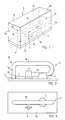
- Figure 1 shows a resonator of a single-circuit filter in its shell,
- Figure 2 is a side view of the resonator shown in Figure 1 on the bottom of the shell construction,
- Figure 3 is a top view of the resonator shown in Figure 1 on the bottom of the shell construction,
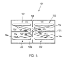
- Figure 4 shows a 4-circuit filter.
- With reference to Figures 1 to 3, it is first stated that the invention relates to an RF filter 1, i.e. a radio-frequency filter 1, comprising a
shell construction 2 and at least one coaxial resonator 3 in the shell construction. Theshell construction 2 comprises abottom 2a,walls 2b to 2e and acover 2f. Theshell construction 2 defines acompartment 2g where the coaxial resonator is located. Both the shell construction and the resonator are naturally of an electroconductive material. The coaxial resonator 3 is formed for example of a thin copper wire having a thickness of 1.5 mm, for instance. Theshell construction 2 may be of aluminium, for example. In the filter 1, the resonator 3 may be attached to aconnection surface 2a included in the shell construction, which is formed of thebottom 2a of the shell construction in the preferred embodiment. The connection is carried out at aconnection point 6. Theconnection point 6 can be a soldered joint, a screw joint or some other joint, or the resonator may be integrated as an integral part of thebottom 2a. In the drawings e.g. a soldered joint or a screw joint is used. - It can be seen in Figures 1 and 2 that in some area after the initial section of the resonator 3, at the end section of the resonator at the latest, the resonator 3 rests on a supporting
means 4 which is attached to thesame connection surface 2a to which the resonator 3 is attached. The resonator 3 comprises aninitial section 3a extending from thesurface 2a, anintermediate section 3b, a turning point 3c where the resonator turns backwards, and anend section 3d. In the preferred embodiment of the invention, the resonator 3 bears on theconnection point 2a in the area of the turning point 3c of the resonator 3 and/or in the area after the turning point, that is, according to the figures, precisely in the area after the turning point 3c, that is, in the area of theend section 3d of the resonator 3 some distance after the turning point 3c. It can also be seen in the figure that in the preferred embodiment, the resonator comprises aninitial section 3a extending from theconnection surface 2a and in addition, aturning area 30 and anintermediate section 3b before said turning point 3c of the resonator. This kind of a resonator is easy to manufacture, and in accordance with the invention, it makes it possible to attach to and rest on the same surface, that is, in practice, thebottom 2a of the shell construction. - The
support 4 of the coaxial resonator 3 is such that thesupport 4 of the coaxial resonator 3 against thissame connection surface 2a is arranged in the essentiallystraight section 3d of the coaxial resonator after the turning point 3c of the coaxial resonator and/or in the area of the turning point 3c preceding this essentiallystraight section 3d. - In one preferred embodiment of the invention the coaxial resonator is a hooked bar-like coaxial resonator since the Applicant has observed that this provides a better Q factor than a strip-like construction, for example. A resonator formed of a sufficiently rigid metallic wire can also be interpreted as being hooked.
- As was mentioned above, in the preferred embodiment of the invention, the filter is such that the
connection surface 2a included in theshell construction 2, to which surface to the resonator 3 is attached and on which the turning point 3c and/or thesection 3d of the resonator 3 after the turning point 3c rests, is thebottom 2a of the shell construction of the filter. In this case the manufacture and installation of the filter will be as easy as possible. - In the filter, a temperature rise may extend the length of the resonator 3 and thus lower resonance frequency. On the other hand, a temperature rise may cause the
end section 3d of the resonator to straighten and come closer to thebottom 2a of the shell construction, in which case the capacitance between thebottom 2a and the resonator would change as the distance becomes shorter. To eliminate these disadvantages, that is, to effect temperature compensation at the same time, the solution in the preferred embodiment of the invention is such that a supportingmeans 4 is used in the support between the resonator and theconnection surface 2a (thebottom 2a), the supportingmeans 4 extending its length due to heat. Teflon is a suitable material for the supportingmeans 4. - In the embodiment of the figures, the resonator 3 is positioned so that because of heat and straightening, the resonator 3 and the
bottom 2a will come closer. In that case the solution in the preferred embodiment of the invention is such that the supportingmeans 4 extends its length due to heat, whereby the supporting means, such as a piece of teflon makes the distance greater between the resonator and thesurface 2a, that is, thebottom 2a, compensating the disadvantageous effect in the opposite direction. - It can be seen in the figure that in the preferred embodiment of the invention, the filter comprises a
means 5 for adjusting the resonance frequency of the filter and that themeans 5 for adjusting the resonance frequency of the filter is attached to thesame connection surface 2a to which the resonator is attached and on which the turning point and/or the section of the resonator after the turning point 3c rests. In that case, all the important constructions, that is, the connection, support, temperature compensation of the resonator, and thus in this preferred embodiment also themeans 5 for adjusting the resonance frequency of the filter are attached to thesame connection surface 2a, that is, thebottom 2a. - It can be seen in the figures that in the preferred embodiment of the invention, the filter is such that the
section 3d of the resonator 3 after the turning point 3c is positioned close to theconnection point 6, that is, the joint of the resonator 3 and itsconnection surface 2a. Theinitial section 3a and theend section 3d of the resonator are thus close to one another. The Applicant has observed that a better quality factor, i.e. Q factor is then attained. The Applicant has observed that a quality factor of over 1,400 can be attained with the method of the invention. For example, resonance frequency and the size of the resonator and the shell also have an effect on the quality factor. - It can be seen in particular in Figure 3 that the resonator is a piece on one plane. This kind of a resonator is easy to manufacture and install.
- With reference to Figures 1 to 3, in the preferred embodiment of the invention, the end section of the resonator is directed at least approximately towards the initial section of the resonator. The Applicant has noticed that in this way the quality factor, i.e. the Q factor is improved and the resonator is maintained on a plane.
- The embodiment of Figure 4 will be discussed in the following. Figure 4 shows a
filter 101, which is a multi-circuit filter and comprisesseveral resonators shell construction 103 comprisingcompartments 111 to 114, that is, a compartment for eachresonator compartments 111 to 114 together withcorresponding resonators - Figure 4 also illustrates resonance-specific adjustment means 105 for adjusting the resonator frequency of the filter. Supporting means can also be seen there.
Reference numeral 103a illustrates the bottom of the shell construction. - With reference to Figure 4, in the preferred embodiment the end section of the resonator is directed past the initial section of the resonator. In this way a good quality factor, i.e. Q factor is attained.
- It can be seen in Figure 4 that in the preferred embodiment of the invention, different resonators are directed to the vicinity of one or more adjacent circuits of a resonator. Then it possible to carry out switching between adjacent resonator circuits more easily. The shell construction should have
openings 200 between the compartments of the shell construction to enable switching between resonator circuits. - The Q factor can be even further improved with some preferred embodiments of the invention and the construction of the coaxial resonator can still remain suitably simple to manufacture and install.
- In one such preferred embodiment the
initial section 3a of the coaxial resonator is essentially straight as then the construction of the resonator will remain simple. - Correspondingly and for this same reason in one preferred embodiment, the
intermediate section 3b after the turningarea 30 subsequent to theinitial section 3a of the coaxial resonator is essentially straight. In one such preferred embodiment, theinitial section 3a of the coaxial resonator extends essentially at a straight angle outwards from the connection surface. Then there will be sufficient distance with respect to theconnection surface 2a and the resonator is provided with more length. - In another preferred embodiment, the
intermediate section 3b of the coaxial resonator extends essentially in the same direction as the connection surface. - In one preferred embodiment, the
section 3d of the coaxial resonator after the turning point 3c extends essentially in the same direction as theconnection surface 2a. - In one preferred embodiment, the
intermediate section 3b of the coaxial resonator is at least approximately at a straight angle with respect to theinitial section 3a of the bar-like coaxial resonator. - In one preferred embodiment, the
intermediate section 3b of the coaxial resonator and theend section 3d after the turning point are essentially parallel, having a constant distance from one another. - All the above preferred embodiments improve the advantages of the invention, especially with regard to manufacture, installation and the Q factor.
- Although the invention has been described above with reference to the examples illustrated in the accompanying drawings, it will be clear that the invention is not restricted to these examples but can be modified in many ways within the inventive concept disclosed in the appended claims.
Claims (20)
- A filter comprising a shell construction (2, 2a to 2f) and at least one coaxial resonator (3, 3a to 3d) in the shell construction, and in which filter the coaxial resonator (3, 3a to 3d) comprises a turning point (3c) where the coaxial resonator turns backwards, and in which filter the coaxial resonator (3, 3a to 3d) is attached to a connection surface (2a) included in the shell construction (2, 2a to 2f), characterized in that the coaxial resonator (3) rests on a supporting means (4) which is attached to the same connection surface (2a) to which the coaxial resonator (3) is attached, and that the support (4) of the coaxial resonator is such that the support (4) of the coaxial resonator (3, 3a to 3d) against this same connection surface (2a) is arranged in the essentially straight section (3d) of the coaxial resonator after the turning point (3c) of the coaxial resonator and/or in the area of the turning point (3c) preceding this essentially straight section (3d).
- A filter according to claim 1, characterized in that the coaxial resonator is a hooked bar-like coaxial resonator.
- A filter according to claim 1, characterized in that the connection surface (2a) included in the shell construction, to which surface the coaxial resonator (3) is attached and on which the turning point (3c) and/or the section (3d) after the turning point (3c) rests, is the bottom (2a) of the shell construction (2) of the filter.
- A filter according to claim 1, characterized in that a supporting means (4) is used in the support between the coaxial resonator (3) and the connection surface (2a), the supporting means being a supporting means (4) that changes its length due to heat for carrying out temperature compensation of the coaxial resonator (3).
- A filter according to claim 4, characterized in that the supporting means (4) is a supporting means that extends its length due to heat.
- A filter according to claim 1, characterized in that the filter comprises a means (5) for adjusting resonator frequency of the filter, and that said means (5) for adjusting resonator frequency of the filter is attached to the same connection surface (2a) to which the coaxial resonator (3) is attached and on which the turning point (3c) and/or the section (3d) after the turning point (3c) rests.
- A filter according to claim 1, characterized in that the section (3d) of the coaxial resonator after the turning point (3c) is positioned close to a connection point (6) of the coaxial resonator and its connection surface (2a).
- A filter according to claim 1, characterized in that the coaxial resonator (3) is a piece on one plane.
- A filter according to claim 1, characterized in that the end section (3d) of the coaxial resonator, that is, the section (3d) after the turning point is directed at least approximately towards the initial section (3a) of the coaxial resonator.
- A filter according to claim 1, characterized in that the end section (3d) of the coaxial resonator, that is, the section (3d) after the turning point is directed past the initial section (3a) of the coaxial resonator.
- A filter according to claim 1, characterized in that a filter (101) is a multi-circuit filter and it comprises several coaxial resonators (102, 202, 302, 402).
- A filter according to claim 1, characterized in that different coaxial resonators are directed to the vicinity of one or more adjacent resonator circuits of a coaxial resonator.
- A filter according to claim 1, characterized in that the coaxial resonator comprises an initial section (3a) extending from the connection surface (2a) and also a turning area (30) and an intermediate section (3b) before said turning point (3c) of the resonator.
- A filter according to claim 13, characterized in that the initial section (3a) of the coaxial resonator is essentially straight.
- A filter according to claim 13, characterized in that the intermediate section (3b) after the turning point (30) subsequent to the initial section (3a) of the coaxial resonator is essentially straight.
- A filter according to claim 13, characterized in that the initial section (3a) of the coaxial resonator extends essentially at a straight angle outwards from the connection surface.
- A filter according to claim 13, characterized in that the intermediate section (3b) of the coaxial resonator extends essentially in the same direction as the connection surface.
- A filter according to claim 1, characterized in that the section (3d) of the coaxial resonator after the turning point (3c) extends essentially in the same direction as the connection surface (2a).
- A filter according to claim 13, characterized in that the intermediate section (3b) of the coaxial resonator is at least approximately at a straight angle with respect to the initial section (3a) of the bar-like coaxial resonator.
- A filter according to claim 13, characterized in that the intermediate section (3b) of the coaxial resonator and the end section (3d) after the turning point are essentially parallel, having a constant distance from one another.
Applications Claiming Priority (2)
| Application Number | Priority Date | Filing Date | Title |
|---|---|---|---|
| FI961940 | 1996-05-07 | ||
| FI961940A FI110393B (en) | 1996-05-07 | 1996-05-07 | Filter |
Publications (4)
| Publication Number | Publication Date |
|---|---|
| EP0806807A2 true EP0806807A2 (en) | 1997-11-12 |
| EP0806807A3 EP0806807A3 (en) | 1998-07-29 |
| EP0806807B1 EP0806807B1 (en) | 2003-03-12 |
| EP0806807B8 EP0806807B8 (en) | 2003-08-13 |
Family
ID=8545977
Family Applications (1)
| Application Number | Title | Priority Date | Filing Date |
|---|---|---|---|
| EP97660053A Expired - Lifetime EP0806807B8 (en) | 1996-05-07 | 1997-05-05 | Filter |
Country Status (6)
| Country | Link |
|---|---|
| US (1) | US5874872A (en) |
| EP (1) | EP0806807B8 (en) |
| AT (1) | ATE234516T1 (en) |
| DE (2) | DE69719593T2 (en) |
| FI (1) | FI110393B (en) |
| GB (1) | GB2312993B (en) |
Cited By (1)
| Publication number | Priority date | Publication date | Assignee | Title |
|---|---|---|---|---|
| WO2000025429A1 (en) * | 1998-10-22 | 2000-05-04 | Gregory Michael Orme | A method of compressing data and compressible devices |
Family Cites Families (8)
| Publication number | Priority date | Publication date | Assignee | Title |
|---|---|---|---|---|
| BE469698A (en) * | 1945-03-10 | |||
| DE1170020B (en) * | 1962-11-26 | 1964-05-14 | Nordmende | Tuning device for the reception of decimeter waves |
| US3706948A (en) * | 1971-02-18 | 1972-12-19 | Motorola Inc | Comb-line filter structure having reduced length and width |
| CA1080313A (en) * | 1975-07-31 | 1980-06-24 | Matsushita Electric Industrial Co., Ltd. | Coaxial cavity resonator |
| JPS5299746A (en) * | 1976-02-18 | 1977-08-22 | Toshiba Corp | Microstrip line |
| FI90157C (en) * | 1990-05-04 | 1993-12-27 | Lk Products Oy | Helix resonator support device |
| FI92265C (en) * | 1992-11-23 | 1994-10-10 | Lk Products Oy | Radio frequency filter, whose helix resonators on the inside are supported by an insulation plate |
| WO1995027318A1 (en) * | 1994-03-31 | 1995-10-12 | Nihon Dengyo Kosaku Co., Ltd. | Resonator and filter using it |
-
1996
- 1996-05-07 FI FI961940A patent/FI110393B/en not_active IP Right Cessation
-
1997
- 1997-05-05 US US08/851,446 patent/US5874872A/en not_active Expired - Fee Related
- 1997-05-05 DE DE69719593T patent/DE69719593T2/en not_active Expired - Fee Related
- 1997-05-05 AT AT97660053T patent/ATE234516T1/en not_active IP Right Cessation
- 1997-05-05 EP EP97660053A patent/EP0806807B8/en not_active Expired - Lifetime
- 1997-05-07 DE DE29708224U patent/DE29708224U1/en not_active Expired - Lifetime
- 1997-05-07 GB GB9709242A patent/GB2312993B/en not_active Expired - Fee Related
Cited By (1)
| Publication number | Priority date | Publication date | Assignee | Title |
|---|---|---|---|---|
| WO2000025429A1 (en) * | 1998-10-22 | 2000-05-04 | Gregory Michael Orme | A method of compressing data and compressible devices |
Also Published As
| Publication number | Publication date |
|---|---|
| DE69719593T2 (en) | 2004-01-08 |
| GB2312993A (en) | 1997-11-12 |
| EP0806807A3 (en) | 1998-07-29 |
| DE69719593D1 (en) | 2003-04-17 |
| EP0806807B8 (en) | 2003-08-13 |
| US5874872A (en) | 1999-02-23 |
| DE29708224U1 (en) | 1997-07-10 |
| GB9709242D0 (en) | 1997-06-25 |
| ATE234516T1 (en) | 2003-03-15 |
| FI110393B (en) | 2003-01-15 |
| EP0806807B1 (en) | 2003-03-12 |
| FI961940L (en) | 1997-11-08 |
| FI961940A0 (en) | 1996-05-07 |
| GB2312993B (en) | 1998-07-01 |
Similar Documents
| Publication | Publication Date | Title |
|---|---|---|
| AU687240B2 (en) | Method for tuning a summing network of a base station, and a bandpass filter | |
| EP1604425B1 (en) | Resonator filter | |
| EP0567266B1 (en) | Helix resonator | |
| US5949309A (en) | Dielectric resonator filter configured to filter radio frequency signals in a transmit system | |
| US5689221A (en) | Radio frequency filter comprising helix resonators | |
| US4142164A (en) | Dielectric resonator of improved type | |
| EP1251588A3 (en) | Method for tuning an antenna and an antenna | |
| WO2000052784A1 (en) | Integrable multiband antenna | |
| EP0924790B1 (en) | Filter | |
| US9812751B2 (en) | Plurality of resonator cavities coupled by inductive apertures which are adjusted by capacitive parts | |
| KR100561694B1 (en) | Radio frequency filter with dielectric with high dielectric constant and high selectivity values | |
| WO1999030383A2 (en) | Resonator structure | |
| US5874872A (en) | Filter | |
| CN107331927A (en) | A kind of minimized wide-band electricity adjusts cavity body filter | |
| JPH07193419A (en) | Tunable circuit board antenna and its tuning method | |
| CN101978551A (en) | A microwave filter | |
| US5892419A (en) | Integral resonators for a filter and a method for manufacturing thereof | |
| US5666093A (en) | Mechanically tunable ceramic bandpass filter having moveable tabs | |
| US6060965A (en) | Dielectric resonator and filter including capacitor electrodes on a non-conductive surface | |
| US6566984B2 (en) | Resonator filter with reduced variation in the pass band attenuation | |
| KR20070013983A (en) | Resonator filter coupled with curved conductor plate | |
| US4070627A (en) | Double tuned input circuit for television transmitter amplifier | |
| US5781088A (en) | Lumped-constant resonator structure and method for adjusting it | |
| US6198364B1 (en) | Resonator filter having a frequency regulating means with at least one turn | |
| EP0797267A2 (en) | Radio frequency filter and a method for adjusting the frequency response thereof |
Legal Events
| Date | Code | Title | Description |
|---|---|---|---|
| PUAI | Public reference made under article 153(3) epc to a published international application that has entered the european phase |
Free format text: ORIGINAL CODE: 0009012 |
|
| 17P | Request for examination filed |
Effective date: 19970508 |
|
| AK | Designated contracting states |
Kind code of ref document: A2 Designated state(s): AT CH DE DK ES FR GB IT LI NL SE |
|
| PUAL | Search report despatched |
Free format text: ORIGINAL CODE: 0009013 |
|
| AK | Designated contracting states |
Kind code of ref document: A3 Designated state(s): AT CH DE DK ES FR GB IT LI NL SE |
|
| GRAH | Despatch of communication of intention to grant a patent |
Free format text: ORIGINAL CODE: EPIDOS IGRA |
|
| GRAH | Despatch of communication of intention to grant a patent |
Free format text: ORIGINAL CODE: EPIDOS IGRA |
|
| GRAA | (expected) grant |
Free format text: ORIGINAL CODE: 0009210 |
|
| RAP1 | Party data changed (applicant data changed or rights of an application transferred) |
Owner name: REMEC OY |
|
| AK | Designated contracting states |
Designated state(s): AT CH DE DK ES FR GB IT LI NL SE |
|
| PG25 | Lapsed in a contracting state [announced via postgrant information from national office to epo] |
Ref country code: NL Free format text: LAPSE BECAUSE OF FAILURE TO SUBMIT A TRANSLATION OF THE DESCRIPTION OR TO PAY THE FEE WITHIN THE PRESCRIBED TIME-LIMIT Effective date: 20030312 Ref country code: LI Free format text: LAPSE BECAUSE OF FAILURE TO SUBMIT A TRANSLATION OF THE DESCRIPTION OR TO PAY THE FEE WITHIN THE PRESCRIBED TIME-LIMIT Effective date: 20030312 Ref country code: FR Free format text: LAPSE BECAUSE OF FAILURE TO SUBMIT A TRANSLATION OF THE DESCRIPTION OR TO PAY THE FEE WITHIN THE PRESCRIBED TIME-LIMIT Effective date: 20030312 Ref country code: CH Free format text: LAPSE BECAUSE OF FAILURE TO SUBMIT A TRANSLATION OF THE DESCRIPTION OR TO PAY THE FEE WITHIN THE PRESCRIBED TIME-LIMIT Effective date: 20030312 Ref country code: AT Free format text: LAPSE BECAUSE OF FAILURE TO SUBMIT A TRANSLATION OF THE DESCRIPTION OR TO PAY THE FEE WITHIN THE PRESCRIBED TIME-LIMIT Effective date: 20030312 |
|
| REG | Reference to a national code |
Ref country code: GB Ref legal event code: FG4D |
|
| REG | Reference to a national code |
Ref country code: CH Ref legal event code: EP |
|
| REF | Corresponds to: |
Ref document number: 69719593 Country of ref document: DE Date of ref document: 20030417 Kind code of ref document: P |
|
| PG25 | Lapsed in a contracting state [announced via postgrant information from national office to epo] |
Ref country code: DK Free format text: LAPSE BECAUSE OF FAILURE TO SUBMIT A TRANSLATION OF THE DESCRIPTION OR TO PAY THE FEE WITHIN THE PRESCRIBED TIME-LIMIT Effective date: 20030612 |
|
| REG | Reference to a national code |
Ref country code: SE Ref legal event code: TRGR |
|
| RTI2 | Title (correction) |
Free format text: FILTER |
|
| NLV1 | Nl: lapsed or annulled due to failure to fulfill the requirements of art. 29p and 29m of the patents act | ||
| REG | Reference to a national code |
Ref country code: CH Ref legal event code: PL |
|
| PG25 | Lapsed in a contracting state [announced via postgrant information from national office to epo] |
Ref country code: ES Free format text: LAPSE BECAUSE OF FAILURE TO SUBMIT A TRANSLATION OF THE DESCRIPTION OR TO PAY THE FEE WITHIN THE PRESCRIBED TIME-LIMIT Effective date: 20030930 |
|
| PLBE | No opposition filed within time limit |
Free format text: ORIGINAL CODE: 0009261 |
|
| STAA | Information on the status of an ep patent application or granted ep patent |
Free format text: STATUS: NO OPPOSITION FILED WITHIN TIME LIMIT |
|
| EN | Fr: translation not filed | ||
| 26N | No opposition filed |
Effective date: 20031215 |
|
| PGFP | Annual fee paid to national office [announced via postgrant information from national office to epo] |
Ref country code: GB Payment date: 20040427 Year of fee payment: 8 |
|
| PGFP | Annual fee paid to national office [announced via postgrant information from national office to epo] |
Ref country code: SE Payment date: 20040519 Year of fee payment: 8 |
|
| PGFP | Annual fee paid to national office [announced via postgrant information from national office to epo] |
Ref country code: DE Payment date: 20040525 Year of fee payment: 8 |
|
| PG25 | Lapsed in a contracting state [announced via postgrant information from national office to epo] |
Ref country code: IT Free format text: LAPSE BECAUSE OF NON-PAYMENT OF DUE FEES;WARNING: LAPSES OF ITALIAN PATENTS WITH EFFECTIVE DATE BEFORE 2007 MAY HAVE OCCURRED AT ANY TIME BEFORE 2007. THE CORRECT EFFECTIVE DATE MAY BE DIFFERENT FROM THE ONE RECORDED. Effective date: 20050505 Ref country code: GB Free format text: LAPSE BECAUSE OF NON-PAYMENT OF DUE FEES Effective date: 20050505 |
|
| PG25 | Lapsed in a contracting state [announced via postgrant information from national office to epo] |
Ref country code: SE Free format text: LAPSE BECAUSE OF NON-PAYMENT OF DUE FEES Effective date: 20050506 |
|
| PG25 | Lapsed in a contracting state [announced via postgrant information from national office to epo] |
Ref country code: DE Free format text: LAPSE BECAUSE OF NON-PAYMENT OF DUE FEES Effective date: 20051201 |
|
| EUG | Se: european patent has lapsed | ||
| GBPC | Gb: european patent ceased through non-payment of renewal fee |
Effective date: 20050505 |