EP0806715A1 - Method for controlling a computer driven storage shelf device - Google Patents
Method for controlling a computer driven storage shelf device Download PDFInfo
- Publication number
- EP0806715A1 EP0806715A1 EP95118823A EP95118823A EP0806715A1 EP 0806715 A1 EP0806715 A1 EP 0806715A1 EP 95118823 A EP95118823 A EP 95118823A EP 95118823 A EP95118823 A EP 95118823A EP 0806715 A1 EP0806715 A1 EP 0806715A1
- Authority
- EP
- European Patent Office
- Prior art keywords
- storage
- control circuit
- drive
- current
- retrieval
- Prior art date
- Legal status (The legal status is an assumption and is not a legal conclusion. Google has not performed a legal analysis and makes no representation as to the accuracy of the status listed.)
- Granted
Links
- 238000000034 method Methods 0.000 title claims abstract description 18
- 238000003860 storage Methods 0.000 title claims description 40
- 238000005259 measurement Methods 0.000 claims abstract description 5
- 230000001105 regulatory effect Effects 0.000 claims description 6
- 238000005265 energy consumption Methods 0.000 claims description 3
- 238000006073 displacement reaction Methods 0.000 claims description 2
- 230000001133 acceleration Effects 0.000 description 13
- 230000006399 behavior Effects 0.000 description 7
- 238000013178 mathematical model Methods 0.000 description 4
- 238000012546 transfer Methods 0.000 description 4
- 230000008901 benefit Effects 0.000 description 3
- 238000013016 damping Methods 0.000 description 3
- 238000013461 design Methods 0.000 description 3
- 238000005457 optimization Methods 0.000 description 3
- 230000008569 process Effects 0.000 description 3
- 230000003068 static effect Effects 0.000 description 3
- 230000003044 adaptive effect Effects 0.000 description 2
- 230000008859 change Effects 0.000 description 2
- 238000010276 construction Methods 0.000 description 2
- 230000005284 excitation Effects 0.000 description 2
- 230000006870 function Effects 0.000 description 2
- 238000012544 monitoring process Methods 0.000 description 2
- 238000001228 spectrum Methods 0.000 description 2
- 238000012360 testing method Methods 0.000 description 2
- 238000005303 weighing Methods 0.000 description 2
- 230000006978 adaptation Effects 0.000 description 1
- 230000033228 biological regulation Effects 0.000 description 1
- 230000005540 biological transmission Effects 0.000 description 1
- 239000000969 carrier Substances 0.000 description 1
- 238000004891 communication Methods 0.000 description 1
- 230000008094 contradictory effect Effects 0.000 description 1
- 230000036461 convulsion Effects 0.000 description 1
- 238000012937 correction Methods 0.000 description 1
- 230000001186 cumulative effect Effects 0.000 description 1
- 230000007423 decrease Effects 0.000 description 1
- 230000001419 dependent effect Effects 0.000 description 1
- 238000003745 diagnosis Methods 0.000 description 1
- 238000010586 diagram Methods 0.000 description 1
- 230000000694 effects Effects 0.000 description 1
- 230000008030 elimination Effects 0.000 description 1
- 238000003379 elimination reaction Methods 0.000 description 1
- 238000005516 engineering process Methods 0.000 description 1
- 230000007613 environmental effect Effects 0.000 description 1
- 238000009434 installation Methods 0.000 description 1
- 239000002184 metal Substances 0.000 description 1
- 230000009467 reduction Effects 0.000 description 1
- 238000009987 spinning Methods 0.000 description 1
- 239000000725 suspension Substances 0.000 description 1
- 230000007704 transition Effects 0.000 description 1
Images
Classifications
-
- G—PHYSICS
- G05—CONTROLLING; REGULATING
- G05B—CONTROL OR REGULATING SYSTEMS IN GENERAL; FUNCTIONAL ELEMENTS OF SUCH SYSTEMS; MONITORING OR TESTING ARRANGEMENTS FOR SUCH SYSTEMS OR ELEMENTS
- G05B19/00—Programme-control systems
- G05B19/02—Programme-control systems electric
- G05B19/18—Numerical control [NC], i.e. automatically operating machines, in particular machine tools, e.g. in a manufacturing environment, so as to execute positioning, movement or co-ordinated operations by means of programme data in numerical form
- G05B19/19—Numerical control [NC], i.e. automatically operating machines, in particular machine tools, e.g. in a manufacturing environment, so as to execute positioning, movement or co-ordinated operations by means of programme data in numerical form characterised by positioning or contouring control systems, e.g. to control position from one programmed point to another or to control movement along a programmed continuous path
-
- B—PERFORMING OPERATIONS; TRANSPORTING
- B66—HOISTING; LIFTING; HAULING
- B66F—HOISTING, LIFTING, HAULING OR PUSHING, NOT OTHERWISE PROVIDED FOR, e.g. DEVICES WHICH APPLY A LIFTING OR PUSHING FORCE DIRECTLY TO THE SURFACE OF A LOAD
- B66F9/00—Devices for lifting or lowering bulky or heavy goods for loading or unloading purposes
- B66F9/06—Devices for lifting or lowering bulky or heavy goods for loading or unloading purposes movable, with their loads, on wheels or the like, e.g. fork-lift trucks
- B66F9/07—Floor-to-roof stacking devices, e.g. "stacker cranes", "retrievers"
-
- Y—GENERAL TAGGING OF NEW TECHNOLOGICAL DEVELOPMENTS; GENERAL TAGGING OF CROSS-SECTIONAL TECHNOLOGIES SPANNING OVER SEVERAL SECTIONS OF THE IPC; TECHNICAL SUBJECTS COVERED BY FORMER USPC CROSS-REFERENCE ART COLLECTIONS [XRACs] AND DIGESTS
- Y10—TECHNICAL SUBJECTS COVERED BY FORMER USPC
- Y10S—TECHNICAL SUBJECTS COVERED BY FORMER USPC CROSS-REFERENCE ART COLLECTIONS [XRACs] AND DIGESTS
- Y10S706/00—Data processing: artificial intelligence
- Y10S706/902—Application using ai with detail of the ai system
- Y10S706/903—Control
- Y10S706/905—Vehicle or aerospace
Definitions
- the invention relates to a method for regulating a computer-controlled, on a traveling frame a mast with a lifting platform arranged thereon and provided with a load-carrying means, comprising a current control circuit, a drive control circuit including a speed control circuit and a position control circuit.
- Such storage and retrieval machines or conveyors fulfill the transport task, for example in logistic systems which comprise a high-bay warehouse as an essential component, in a fully automatic or manual manner, i.e. the transfer of a loading unit from the storage location to the storage location and from there to the removal location.
- the spectrum of goods to be stored extends from small packages weighing only a few kilograms to coils weighing around 40 tons, for example metal strips wound into bundles.
- the storage heights and, depending on this, the height of the storage and retrieval machines are in a range from approx. 6 m to 45 m.
- the respective storage dimensions are opened up by the freely movable or guided rack operator device by its travel drive in the horizontal X direction, by the lifting drive of the lifting drive which can be moved vertically on the vertical mast for the lifting platform in the vertical Y direction and by the load suspension device drive in the Z direction .
- the tall, slim masts, on which the already mentioned, sometimes quite large loads are moved up and down, are flexible, extremely vibratory systems with variable dynamic properties, which e.g. can be stimulated by motor acceleration and deceleration, road impacts, brake application and controller influence.
- Drive controllers for lifting and travel drives with interfaces to different variable-speed electrical drives used for this purpose are servomotors with servo drive amplifiers, DC motors with converters and three-phase asynchronous motors with frequency converters.
- the interfaces mentioned delimit the controller hierarchically downwards; the upward interface is specified by the storage and retrieval machine control, which notifies the controller of the target points of the travel movements and for Safety functions, limit switches, coordination tasks, error diagnosis, communication to the warehouse management computer, etc. is responsible.
- a position measuring system which transmits the current position of the storage and retrieval machine to the controller via absolute or indirect measurement.
- the so-called “3-point position controller” and the “cascade controller”, which are based on three different, cascade-shaped controller circuits, are the state-of-the-art controller concepts: the current control loop as the inner circle, the speed control loop and the position control loop as the outer circle. Strictly speaking, of these controller concepts, the "3-point position controller” is not a position controller, but rather a path-dependent speed control, with the result that a multi-stage deceleration process with time losses occurs. Since there is no continuous comparison between the actual position and the setpoint, the cumulative position differences can only be compensated for at the end of the deceleration process during slow speed travel at a reduced speed.
- the multi-stage positioning thus brings with it multiple changes in speed and thus also changes in acceleration and deceleration, which favors vibrations of the mast of the storage and retrieval machine.
- the "cascade controller” is characterized by the fact that a continuous comparison of the actual position and setpoint takes place and positional differences are actively compensated for by adjusting the speed setpoint. Due to this concept, there are fewer starting points for vibration excitation.
- a passive method is therefore used in both controller concepts by limiting the change in acceleration over time or the associated jerk by specifying a suitable command variable. Accordingly, there is a transition from a sudden change in acceleration to a linearly increasing or to a sinusoidal rounding. This vibration minimization is disadvantageous however, that due to the rounding while maintaining the maximum acceleration value, the average acceleration decreases, which is inevitably associated with wasted time.
- the invention is therefore based on the object of creating a generic control method of the type mentioned at the outset, which makes it possible to decisively expand the intervention options and narrow technical limits which are limited in the known controller concepts.
- This object is achieved in that the instantaneous dynamic behavior of the storage and retrieval machine is calculated from an existing data base of a status and fault observer controller module using existing measurement and control variables that contain information about the device dynamics and on the basis of coefficient maps on the basis of a basic setting of the sizes of the storage and retrieval machine and an iterative estimation algorithm from a controller module that performs automatic self-learning coefficient identification.
- a self-learning adaptive state controller which takes into account an active vibration damping which takes into account the current dynamic state of the storage and retrieval unit, which results in a considerably broader spectrum of optimization options.
- the control procedure integrates further information containing information about the current dynamic behavior of the storage and retrieval machine, e.g. the mast deflection and relative speed of the mast tip and the position deviation in the case of positive toothed belt drives.
- This additional information or device-dynamic variables for describing the device dynamics are not obtained by measurement technology, but rather are calculated from existing data with the aid of a mathematical model of the state and fault observer controller module, for example the mast deflection and relative speed from the existing current signal.
- the control method according to the invention does not have constant coefficients, but rather coefficient characteristic maps. This takes into account that in practice the coefficients depend on, for example, the current position of the lifting platform, the size of the payload and other influencing variables, all of which are covered by the characteristic diagrams. So that these do not have to be time-consuming to determine in a demanding process, the controller module carries out an automatic self-learning coefficient identification by determining the characteristic fields on the basis of a basic setting with the aid of the mathematical model of the storage and retrieval machine and an iterative estimation algorithm.
- the learning mode of the controller module takes place in the form that a test run is carried out automatically and an additional current test signal is applied as a reference variable in the constant travel phase. From the target / actual comparison, the estimation algorithm calculates the parameters of the transfer function, which in turn lead to the coefficient maps using the mathematical model.
- a preferred embodiment of the invention provides that the current wheel pressure of the storage and retrieval machine is calculated by the status and fault observer controller module and the drive torque or the motor current is limited to the currently possible maximum in the drive or speed control loop. This allows the effects of the dynamics of the storage and retrieval machine on the wheel pressures between the wheels or drive wheels and the rail or the foundation to be taken into account.
- the driven wheels transmit lower frictional forces, which can lead to slippage in the acceleration or deceleration phases and thus to the wheels spinning or locking.
- the active vibration damping already counteracts this influence significantly, the torque monitoring enables the elimination of this influence in the drive control circuit due to a corresponding controller module.
- the current wheel pressure and the drive torque or the are calculated continuously Motor current currently adjusted accordingly.
- the advantage of the torque monitoring controller module is consequently that the instantaneous maximum acceleration or braking torque is always transmitted in accordance with the dynamic behavior of the storage and retrieval unit.
- the torque or motor current regulator loop is superimposed by a continuous comparison of the drive speed and the absolute speed of the storage and retrieval machine, including an absolute displacement measuring system.
- differences caused by slip cause the controller to correct the motor current.
- the energy consumption of the storage and retrieval machine is regulated depending on the current load.
- the invention further provides that the positioning accuracy of the storage and retrieval unit is regulated differently, adapted to the different transport units or stored goods.
- the respective positioning tolerance can be freely selected depending on the respective transport unit. This makes it possible to take into account the wide range of goods to be stored in terms of weight, dimensions and load carriers.
- the different transport units require different position tolerances for the safe transfer from the storage and retrieval machine into the storage compartment of the high-bay warehouse, whereby the positioning controller module ensures that the positioning accuracy is not higher than absolutely necessary in order to keep the seasons as short as possible.
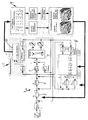
- the controller 1 comprises a reference variable generator 3, a cascade controller 4 with a position controller 5 and a speed controller 6, as well as one Current controllers 7. These are linked via appropriate control loops both to the storage and retrieval unit 2 and to a status and fault observer controller module 8, which uses a mathematical model to describe the data from existing data the additional information required for the device dynamics.
- This is not based on constant coefficients, but rather on coefficient maps, which are determined by a controller module 9 which carries out an automatic self-learning coefficient identification on the basis of a basic setting of the sizes of the storage and retrieval unit 2 and a module 10 for an iterative estimation algorithm.
- the controller 1 combines the advantages of active vibration damping to eliminate vibrations and shorten the decay time, the position control means that the target point is approached as quickly as possible, optimal control access and less drag error, anti-slip control and - since there is no vibration excitation - higher Acceleration values.
- the control parameters can be optimized taking into account different loads, lifting heights and geometries, a design-related dynamic behavior, different drives and types of power transmission and different static and dynamic deformations.
- freely selectable and, if necessary, combinable operating strategies can be carried out.
Abstract
Description
Die Erfindung betrifft ein Verfahren zum Regeln eines rechnergesteuerten, auf einem Fahrrahmen einen Mast mit einer daran angeordneten, mit einem Lastaufnahmemittel versehenen Hubbühne aufweisendes Regalbediengerät, umfassend einen Stromregel-, einen einen Drehzahlregelkreis einschließenden Antriebsregelkreis und einen Lageregelkreis.The invention relates to a method for regulating a computer-controlled, on a traveling frame a mast with a lifting platform arranged thereon and provided with a load-carrying means, comprising a current control circuit, a drive control circuit including a speed control circuit and a position control circuit.
Derartige Regalbediengeräte bzw. -förderzeuge, wie beispielsweise durch die DE-C 38 03 626 bekanntgeworden, erfüllen beispielsweise in logistischen Systemen, die als eine wesentliche Komponente ein Hochregallager umfassen, in vollautomatischer oder manueller Bedienungsweise die Transportaufgabe, d.h. den Transfer einer Ladeeinheit vom Einlagerungsort zum Lagerplatz und von dort zum Auslagerungsort. Das Spektrum der einzulagernden Güter erstreckt sich vom Kleingebinde mit einem Gewicht von nur wenigen Kilogramm bis zu ca. 40 Tonnen schweren Coils, beispielsweise zu Bunden gewickelte Metallbänder. Die Lagerhöhen und davon abhängig die Höhe der Regalbediengeräte bewegen sich in einem Bereich von ca. 6 m bis 45 m. Die jeweiligen Lagerdimensionen werden von dem frei verfahrbaren oder auf Schienen geführten Regalbediengerät durch dessen Fahrantrieb in horizontaler X-Richtung, durch den Hubantrieb des an dem senkrechten Mast vertikal verfahrbaren Hubantriebes für die Hubbühne in vertikaler Y-Richtung und durch den Lastaufnahmemittelantrieb in Z-Richtung erschlossen. Die hohen, schlanken Maste, an denen die bereits erwähnten, mitunter recht großen Lasten auf- und abbewegt werden, sind biegeweiche, extrem schwingungsfähige Systeme mit variablen dynamischen Eigenschaften, die z.B. durch motorische Beschleunigung und Verzögerung, Fahrbahnstöße, Bremseneinfall und Reglereinfluß angeregt werden können.Such storage and retrieval machines or conveyors, as became known, for example, from DE-C 38 03 626, fulfill the transport task, for example in logistic systems which comprise a high-bay warehouse as an essential component, in a fully automatic or manual manner, i.e. the transfer of a loading unit from the storage location to the storage location and from there to the removal location. The spectrum of goods to be stored extends from small packages weighing only a few kilograms to coils weighing around 40 tons, for example metal strips wound into bundles. The storage heights and, depending on this, the height of the storage and retrieval machines are in a range from approx. 6 m to 45 m. The respective storage dimensions are opened up by the freely movable or guided rack operator device by its travel drive in the horizontal X direction, by the lifting drive of the lifting drive which can be moved vertically on the vertical mast for the lifting platform in the vertical Y direction and by the load suspension device drive in the Z direction . The tall, slim masts, on which the already mentioned, sometimes quite large loads are moved up and down, are flexible, extremely vibratory systems with variable dynamic properties, which e.g. can be stimulated by motor acceleration and deceleration, road impacts, brake application and controller influence.
Unter Kosten-, Leistungs- und Zuverlässigkeitsaspekten kommt im Zuge einer technisch-wirtschaftlichen Optimierung von Regalbediengeräten insbesondere den Fahr- und Hubantrieben einschließlich deren Regelungen eine große Bedeutung zu, da diese neben rein mechanischen Parametern maßgeblich das dynamische Verhalten prägen. Die Ziele der bekannten Steuerungs- und Regelungsstrategien sind die Minimierung der Zeiten zur Ein- bzw. Auslagerung der Lasten (Transporteinheiten bzw. Lagergüter) sowie die Reduzierung der dynamischen Belastung der Struktur und mechanischen Komponenten des Regalbediengerätes. Hierbei ist zu beachten, daß sich die Spielzeiten von Hub- und Fahrantrieb aus reinen Bewegungszeiten und aus Abklingzeiten für die z.B. durch Beschleunigen oder Bremsen angeregten Schwingungen von Hubmast oder -bühne zusammensetzen. Bei einem schwingenden hast kann die Lastübergabe von der Hubbühne auf den Regalstellplatz wegen einer möglichen Beschädigungsgefahr zunächst nicht durchgeführt werden; es muß vielmehr das Abklingen der Amplitude auf einen Grenzwert abgewartet werden. Hieraus läßt sich entnehmen, daß nicht zuletzt das dynamische Verhalten maßgeblich den Durchsatz und damit die Wirtschaftlichkeit eines ein Hochregallager einschließenden logistischen Systems beeinflußt.In terms of costs, performance and reliability, the technical and economic optimization of storage and retrieval machines, in particular the travel and lifting drives, including their controls, is of great importance in addition to purely mechanical parameters, these significantly shape the dynamic behavior. The goals of the known control and regulation strategies are to minimize the times for loading and unloading the loads (transport units or stored goods) and to reduce the dynamic load on the structure and mechanical components of the storage and retrieval machine. It should be noted here that the seasons of the lifting and travel drive are composed of pure movement times and of decay times for the vibrations of the lifting mast or platform, which are excited by acceleration or braking, for example. In the event of a vibrating hurry, the load transfer from the lifting platform to the shelf space cannot be carried out initially because of a possible risk of damage; rather, the decay of the amplitude must be waited for to reach a limit. From this it can be seen that, last but not least, the dynamic behavior significantly influences the throughput and thus the economy of a logistic system including a high-bay warehouse.
Der Forderung nach einer Durchsatzsteigerung durch höhere Beschleunigungen und Geschwindigkeiten steht somit entgegen, daß hierdurch größere Schwingungsamplituden und längere Abklingzeiten unvermeidlich sind; im Ergebnis erhöht sich somit die Spielzeit trotz Verringerung der Bewegungszeit. Als Ansatzpunkte zur Lösung des somit vorliegenden Optimierungsproblems mit widersprüchlichen Zielsetzungen sind die Regler der Antriebe herangezogen worden, da aufgrund der logistischen Aufgabenstellungen und der aus Festigkeitsgründen erforderlichen Dimensionierung die geometrische Gestalt des Regalbediengerätes nur schwerlich verändert werden kann. Zu diesem Zweck eingesetzte Antriebsregler für Hub- und Fahrantrieb mit Schnittstellen zu unterschiedlichen drehzahlveränderlichen elektrischen Antrieben sind Servomotoren mit Servoantriebsverstärkern, Gleichstrommotoren mit Stromrichtern und Drehstrom-Asynchronmotoren mit Frequenzumrichtern. Die genannten Schnittstellen grenzen den Regler hierarchisch gesehen nach unten hin ab; die Schnittstelle nach oben wird durch die Regalbediengeräte-Steuerung vorgegeben, die dem Regler die Zielpunkte der Fahrbewegungen mitteilt und für Sicherheitsfunktionen, Endabschaltungen, Koordinierungsaufgaben, Fehlerdiagnose, Kommunikation zum Lagerverwaltungsrechner, etc. zuständig ist. Hinzu kommt eine externe Schnittstelle zu einem Wegmeßsystem, das dem Regler über Absolut- oder indirekte Messung die momentane Lageposition des Regalbediengerätes übermittelt. Diese Meßsysteme sind in formschlüssiger schlupffreier Ausführung und in reibschlüssiger schlupfbehafteter Ausführung mit anschließender Fachfeinpositionierung üblich.The demand for an increase in throughput due to higher accelerations and speeds therefore stands in the way that larger vibration amplitudes and longer decay times are inevitable; as a result, the playing time increases despite the reduction in movement time. The controllers of the drives have been used as starting points for solving the optimization problem thus present with contradicting objectives, since the geometric shape of the storage and retrieval machine can hardly be changed due to the logistical tasks and the dimensions required for reasons of strength. Drive controllers for lifting and travel drives with interfaces to different variable-speed electrical drives used for this purpose are servomotors with servo drive amplifiers, DC motors with converters and three-phase asynchronous motors with frequency converters. The interfaces mentioned delimit the controller hierarchically downwards; the upward interface is specified by the storage and retrieval machine control, which notifies the controller of the target points of the travel movements and for Safety functions, limit switches, coordination tasks, error diagnosis, communication to the warehouse management computer, etc. is responsible. In addition, there is an external interface to a position measuring system, which transmits the current position of the storage and retrieval machine to the controller via absolute or indirect measurement. These measuring systems are customary in a form-fitting, slip-free design and in a friction-fitting, slip-prone design with subsequent specialist fine positioning.
Zum Stand der Technik zählende Reglerkonzepte sind der sogenannte "3-Punkt-Lageregler" und der "Kaskadenregler", die ausgehend von zunächst drei unterschiedlichen, kaskadenförmig geschalteten Reglerkreisen gebildet werden: Dem Stromregelkreis als inneren Kreis, dem Drehzahlregelkreis und dem Lageregelkreis als äußeren Kreis. Von diesen Reglerkonzepten stellt der "3Punkt-Lageregler" streng genommen keinen Lageregler, sondern eine wegabhängige Drehzahlsteuerung dar, mit der Folge, daß ein mehrstufiger, mit Zeitverlusten behafteter Verzögerungsvorgang entsteht. Da kein kontinuierlicher Abgleich zwischen Lage-Ist- und Sollwert stattfindet, lassen sich die kumulierten Lagedifferenzen erst am Ende des Verzögerungsvorgangs während einer Schleichfahrt mit reduzierter Geschwindigkeit ausgleichen. Die somit mehrstufige Positionierung bringt aber mehrfache Drehzahländerungen und damit auch Änderungen von Beschleunigung und Verzögerung mit sich, was es begünstigt, Schwingungen des Mastes des Regalbediengerätes anzuregen. Im Gegensatz dazu zeichnet den "Kaskadenregler" aus, daß ein kontinuierlicher Vergleich von Lage-Ist- und Sollwert stattfindet und Lagedifferenzen aktiv durch Anpassung des Drehzahlsollwertes ausgeglichen werden. Aufgrund dieses Konzeptes ergeben sich weniger Ansatzpunkte für eine Schwingungsanregung.The so-called "3-point position controller" and the "cascade controller", which are based on three different, cascade-shaped controller circuits, are the state-of-the-art controller concepts: the current control loop as the inner circle, the speed control loop and the position control loop as the outer circle. Strictly speaking, of these controller concepts, the "3-point position controller" is not a position controller, but rather a path-dependent speed control, with the result that a multi-stage deceleration process with time losses occurs. Since there is no continuous comparison between the actual position and the setpoint, the cumulative position differences can only be compensated for at the end of the deceleration process during slow speed travel at a reduced speed. The multi-stage positioning thus brings with it multiple changes in speed and thus also changes in acceleration and deceleration, which favors vibrations of the mast of the storage and retrieval machine. In contrast, the "cascade controller" is characterized by the fact that a continuous comparison of the actual position and setpoint takes place and positional differences are actively compensated for by adjusting the speed setpoint. Due to this concept, there are fewer starting points for vibration excitation.
Zur Schwingungsminimierung wird daher bei beiden Reglerkonzepten ein passives Verfahren genutzt, indem die zeitliche Änderung der Beschleunigung bzw. der damit einhergehende Ruck durch Vorgabe einer geeigneten Führungsgröße begrenzt wird. Es wird demnach von einer sprunghaften Beschleunigungsänderung zu einer linear ansteigenden oder zu einer sinusförmigen Verrundung übergegangen. Nachteilig bei dieser Schwingungsminimierung ist allerdings, daß durch die Verrundung bei Beibehaltung des Beschleunigungsmaximalwertes die mittlere Beschleunigung sinkt, was unvermeidlich mit Zeitverlusten einhergeht.To minimize vibration, a passive method is therefore used in both controller concepts by limiting the change in acceleration over time or the associated jerk by specifying a suitable command variable. Accordingly, there is a transition from a sudden change in acceleration to a linearly increasing or to a sinusoidal rounding. This vibration minimization is disadvantageous however, that due to the rounding while maintaining the maximum acceleration value, the average acceleration decreases, which is inevitably associated with wasted time.
Der Erfindung liegt daher die Aufgabe zugrunde, ein gattungsgemäßes Regelverfahren der eingangs genannten Art zu schaffen, das es ermöglicht, die bei den bekannten Reglerkonzepten beschränkten Eingriffsmöglichkeiten und engen technischen Grenzen entscheidend zu erweitern.The invention is therefore based on the object of creating a generic control method of the type mentioned at the outset, which makes it possible to decisively expand the intervention options and narrow technical limits which are limited in the known controller concepts.
Diese Aufgabe wird erfindungsgemäß dadurch gelöst, daß das momentane dynamische Verhalten des Regalbediengerätes aus einem vorhandenen Datenstamm eines Zustands- und Störbeobachterreglermoduls unter Nutzung von bereits vorhandenen Meß- und Stellgrößen, die Informationen über die Gerätedynamik beinhalten, und anhand von Koeffizienten-Kennfeldern errechnet wird, die ausgehend von einer Basiseinstellung der Größen des Regalbediengerätes und einem iterativen Schätzalgorithmus von einem eine automatische selbstlernende Koeffizienten Identifikation durchführenden Reglermodul ermittelt werden. Es liegt damit ein durch eine aktive, den aktuellen dynamischen Zustand des Regalbediengerätes berücksichtigende Schwingungsdämpfung erweiterter, selbstlernender adaptiver Zustandsregler vor, wodurch sich ein erheblich breiteres Spektrum der Optimierungsmöglichkeiten ergibt. Das Regelverfahren integriert neben dem internen Stromregelkreis, dem Drehzahlregelkreis und dem Lageregelkreis weitere, Aufschluß über das momentane dynamische Verhalten des Regalbediengerätes beinhaltende Informationen, z.B. die Mastauslenkung und relative Geschwindigkeit der Mastspitze und die Lageabweichung bei formschlüssigen Zahnriemenantrieben. Diese zusätzlichen Informationen bzw. gerätedynamischen Größen zur Beschreibung der Gerätedynamik werden nicht meßtechnisch gewonnen, sondern mit Hilfe eines mathematischen Modells des Zustands- und Störbeobachterreglermoduls aus vorhandenen Daten errechnet, beispielsweise die Mastauslenkung und -relativgeschwindigkeit aus dem vorhandenen Stromsignal.This object is achieved in that the instantaneous dynamic behavior of the storage and retrieval machine is calculated from an existing data base of a status and fault observer controller module using existing measurement and control variables that contain information about the device dynamics and on the basis of coefficient maps on the basis of a basic setting of the sizes of the storage and retrieval machine and an iterative estimation algorithm from a controller module that performs automatic self-learning coefficient identification. There is thus an expanded, self-learning adaptive state controller which takes into account an active vibration damping which takes into account the current dynamic state of the storage and retrieval unit, which results in a considerably broader spectrum of optimization options. In addition to the internal current control loop, the speed control loop and the position control loop, the control procedure integrates further information containing information about the current dynamic behavior of the storage and retrieval machine, e.g. the mast deflection and relative speed of the mast tip and the position deviation in the case of positive toothed belt drives. This additional information or device-dynamic variables for describing the device dynamics are not obtained by measurement technology, but rather are calculated from existing data with the aid of a mathematical model of the state and fault observer controller module, for example the mast deflection and relative speed from the existing current signal.
Während die Reglerkoeffizienten der unterschiedlichen Regelkreise bei den bekannten Reglerkonzepten konstante Größen und jeweils nur für einen dynamischen Zustand optimal gesetzt sind, weist das erfindungsgemäße Regelverfahren keine konstanten Koeffizienten, sondern Koeffizienten-Kennfelder auf. Hiermit wird berücksichtigt, daß die Koeffizienten in der Praxis abhängig sind von beispielsweise der aktuellen Position der Hubbühne, der Größe der Nutzlast und weiteren Einflußgrößen, welche sämtlich von den Kennfeldern abgedeckt sind. Damit diese nicht in einem anspruchsvollen Prozeß zeitaufwendig ermittelt werden müssen, führt das Reglermodul eine automatische selbstlernende Koeffizientenidentifikation durch, indem es ausgehend von einer Basiseinstellung mit Hilfe des mathematischen Modells des Regalbediengerätes und einem iterativen Schätzalgorithmus die Kennfelder ermittelt. Der Lernmodus des Reglermoduls geschieht hierbei in der Form, daß automatisch eine Testfahrt abläuft und in der Konstantfahrtphase ein zusätzliches Stromtestsignal als Führungsgröße aufgebracht wird. Aus dem Soll-/Ist-Vergleich errechnet der Schätzalgorithmus die Parameter der Übertragungsfunktion, die wiederum mit Hilfe des mathematischen Modells zu den Koeffizienten-Kennfeldern führen.While the controller coefficients of the different control loops In the known controller concepts, constant variables and in each case optimally set only for a dynamic state, the control method according to the invention does not have constant coefficients, but rather coefficient characteristic maps. This takes into account that in practice the coefficients depend on, for example, the current position of the lifting platform, the size of the payload and other influencing variables, all of which are covered by the characteristic diagrams. So that these do not have to be time-consuming to determine in a demanding process, the controller module carries out an automatic self-learning coefficient identification by determining the characteristic fields on the basis of a basic setting with the aid of the mathematical model of the storage and retrieval machine and an iterative estimation algorithm. The learning mode of the controller module takes place in the form that a test run is carried out automatically and an additional current test signal is applied as a reference variable in the constant travel phase. From the target / actual comparison, the estimation algorithm calculates the parameters of the transfer function, which in turn lead to the coefficient maps using the mathematical model.
Eine bevorzugte Ausgestaltung der Erfindung sieht vor, daß der aktuelle Raddruck des Regalbediengerätes von dem Zustands- und Störbeobachterreglermodul errechnet und im Antriebs- bzw. Drehzahlregelkreis das Antriebsmoment bzw. der Motorstrom auf das aktuell mögliche Maximum begrenzt wird. Hiermit lassen sich die Auswirkungen der Dynamik des Regalbediengerätes auf die Raddrücke zwischen den Lauf- bzw. Antriebsrädern und der Schiene bzw. dem Fundament berücksichtigen. Bei sinkenden Raddrücken übertragen die angetriebenen Räder geringere Reibkräfte, was in Beschleunigungs- bzw. Verzögerungsphasen zu Schlupf- und damit zum Durchdrehen bzw. zum Blockieren der Räder führen kann. Wenngleich die verwirklichte aktive Schwingungsdämpfung diesem Einfluß schon maßgeblich entgegenwirkt, ermöglicht die Drehmomentenüberwachung aufgrund eines entsprechenden Reglermoduls die Eliminierung dieses Einflusses im Antriebsregelkreis. Mit Hilfe des Zustands- und Störbeobachterreglermoduls wird nämlich kontinuierlich der aktuelle Raddruck errechnet und das Antriebsmoment bzw. der Motorstrom entsprechend aktuell angepaßt. Der Vorteil des Drehmomenten-Überwachungsreglermoduls besteht folglich darin, daß stets entsprechend dem dynamischen Verhalten des Regalbediengerätes das momentane Maximum an Beschleunigungs- bzw. Bremsmoment übertragen wird.A preferred embodiment of the invention provides that the current wheel pressure of the storage and retrieval machine is calculated by the status and fault observer controller module and the drive torque or the motor current is limited to the currently possible maximum in the drive or speed control loop. This allows the effects of the dynamics of the storage and retrieval machine on the wheel pressures between the wheels or drive wheels and the rail or the foundation to be taken into account. When the wheel pressures drop, the driven wheels transmit lower frictional forces, which can lead to slippage in the acceleration or deceleration phases and thus to the wheels spinning or locking. Although the active vibration damping already counteracts this influence significantly, the torque monitoring enables the elimination of this influence in the drive control circuit due to a corresponding controller module. With the help of the status and fault observer control module, the current wheel pressure and the drive torque or the are calculated continuously Motor current currently adjusted accordingly. The advantage of the torque monitoring controller module is consequently that the instantaneous maximum acceleration or braking torque is always transmitted in accordance with the dynamic behavior of the storage and retrieval unit.
Nach einer Ausgestaltung der Erfindung wird die Momenten- bzw. Motorstromreglerschleife durch einen kontinuierlichen Vergleich von Antriebsdrehzahl und Absolutgeschwindigkeit des Regalbediengerätes unter Einbeziehung eines Absolut-Wegmeßsystems überlagert. Bei auftretenden, z.B. durch Schlupf hervorgerufenen Differenzen wird in diesem Fall der Regler zu einer Korrektur des Motorstromes veranlaßt.According to one embodiment of the invention, the torque or motor current regulator loop is superimposed by a continuous comparison of the drive speed and the absolute speed of the storage and retrieval machine, including an absolute displacement measuring system. When occurring, e.g. In this case, differences caused by slip cause the controller to correct the motor current.
Wenn vorteilhaft Lageabweichungen des Regalbediengerätes aufgrund von belastungsbedingten Durchbiegungen gegenüber der durch das Absolut-Wegmeßsystem ermittelten Position automatisch korrigiert werden, lassen sich die Einflüsse aufgrund der konstruktionsbedingt exzentrisch am Hubmast geführten Hubbühne ausgleichen. Die Exzentrizität führt nämlich unter dem Einfluß von Eigengewicht und Nutzlast abhängig von der momentanen Hubbühnenhöhe zu einer statischen Durchbiegung und somit zu einer Lageabweichung gegenüber der durch das Wegmeßsystem ermittelten Position. Es bedarf damit keiner einen die Durchsatzproblematik erhöhenden, zusätzlichen Zeitaufwand erfordernden Feinpositionierung, die zudem einen erheblichen Installationsaufwand für Sensorik und Orientierungsmarken erfordert. Dieser Aufwand ist erfindungsgemäß nicht mehr notwendig, weil ein weiteres Reglermodul mit Hilfe des Zustands- und Störbeobachterreglermoduls unter Berücksichtigung von tatsächlicher Last und Hubbühnenhöhe sowie unter Einbeziehung des entsprechenden Verformungskennfeldes den Lagefehler kontinuierlich errechnet und eine automatische Korrektur des Lagesollwertes durchgeführt wird.If advantageous positional deviations of the storage and retrieval machine due to load-related deflections compared to the position determined by the absolute position measuring system are automatically corrected, the influences can be compensated for due to the construction-related eccentric lift mast. The eccentricity, under the influence of its own weight and payload, depending on the current lifting platform height, leads to a static deflection and thus to a positional deviation from the position determined by the position measuring system. There is therefore no need for a fine positioning that increases the throughput problem and requires additional time, which also requires a considerable installation outlay for sensors and orientation marks. This effort is no longer necessary according to the invention, because a further controller module with the aid of the status and fault observer controller module, taking into account the actual load and lifting platform height and also taking into account the corresponding deformation map, continuously calculates the position error and an automatic correction of the position setpoint is carried out.
Nach einer weiteren Ausgestaltung der Erfindung wird der Energieverbrauch des Regalbediengerätes abhängig von der aktuellen Auslastung geregelt. Energiekostensparend und im Sinne des gesteigerten Umweltbewußtseins beinhaltet das erfindungsgemäße Regelverfahren somit ein Strategiereglermodul, das es ermöglicht, entsprechend der aktuellen Auslastungssituation des Regalbediengerätes die jeweils energieminimale Betriebsstrategie bzw. -weise anzuwählen. Bei einer hohen erforderlichen Durchsatzleistung werden Hub- und Fahrantrieb zeitsynchronisiert, d.h. die schnellere Achse wird durch Reduzierung der Beschleunigung bzw. der Verzögerung der langsameren Achse angepaßt. Ist die zu erbringende Durchsatzleistung eher gering, wird entsprechend des tatsächlichen Durchsatzes und damit auftragsabhängig der maximale Energieverbrauch in Form von Beschleunigungs- und Verzögerungsgrenzwerten vorgegeben.According to a further embodiment of the invention, the energy consumption of the storage and retrieval machine is regulated depending on the current load. This includes saving energy costs and increasing environmental awareness Control method according to the invention thus a strategy controller module, which makes it possible to select the energy-minimal operating strategy or mode of operation in accordance with the current utilization situation of the storage and retrieval unit. If the throughput required is high, the stroke and travel drives are time-synchronized, ie the faster axis is adapted by reducing the acceleration or deceleration of the slower axis. If the throughput to be provided is rather low, the maximum energy consumption in the form of acceleration and deceleration limit values is specified in accordance with the actual throughput and thus depending on the order.
Die Erfindung sieht weiterhin vor, daß die Positioniergenauigkeit des Regalbediengerätes an die unterschiedlichen Transporteinheiten bzw. Lagergüter angepaßt verschieden geregelt wird. Durch Integration eines Positionierreglermoduls in das erfindungsgemäße Regelverfahren läßt sich die jeweilige Positioniertoleranz abhängig von der jeweiligen Transporteinheit frei wählen. Hiermit ist es möglich, dem großen Spektrum der einzulagernden Güter hinsichtlich Gewicht, Dimension und Ladungsträger Rechnung zu tragen. Die unterschiedlichen Transporteinheiten erfordern zum sicheren Transfer vom Regalbediengerät in das Lagerfach des Hochregallagers unterschiedliche Lagetoleranzen, wobei sich durch das Positionierreglermodul erreichen läßt, daß zur Einhaltung möglichst geringer Spielzeiten die Positioniergenauigkeit nicht höher ist als unbedingt nötig.The invention further provides that the positioning accuracy of the storage and retrieval unit is regulated differently, adapted to the different transport units or stored goods. By integrating a positioning controller module into the control method according to the invention, the respective positioning tolerance can be freely selected depending on the respective transport unit. This makes it possible to take into account the wide range of goods to be stored in terms of weight, dimensions and load carriers. The different transport units require different position tolerances for the safe transfer from the storage and retrieval machine into the storage compartment of the high-bay warehouse, whereby the positioning controller module ensures that the positioning accuracy is not higher than absolutely necessary in order to keep the seasons as short as possible.
Weitere Einzelheiten und Vorteile der Erfindung ergeben sich aus den Ansprüchen und dem in der Zeichnung dargestellten Reglschema eines selbsteinstellenden, adaptiven Zustandsreglers 1 für ein Regalbediengerät 2. Der Regler 1 umfaßt einen Führungsgrößengenerator 3, einen Kaskadenregler 4 mit einem Lageregler 5 und einem Drehzahlregler 6 sowie einen Stromregler 7. Diese sind über entsprechende Regelkreise sowohl mit dem Regalbediengerät 2 als auch einem Zustands- und Störbeobachterreglermodul 8 verknüpft, das mit Hilfe eines mathematischen Modells aus vorhandenen Daten die zur Beschreibung der Gerätedynamik erforderlichen zusätzlichen Informationen errechnet. Dabei wird nicht von konstanten Koeffizienten, sondern von Koeffizienten-Kennfeldern ausgegangen, die von einem eine automatische selbstlernende Koeffizientenidentifikation durchführenden Reglermodul 9 unter Zugrundelegung einer Basiseinstellung der Größen des Regalbediengerätes 2 und einem Modul 10 für einen iterativen Schätzalgorithmus ermittelt werden.Further details and advantages of the invention emerge from the claims and the control scheme shown in the drawing of a self-adjusting, adaptive state controller 1 for a storage and
Der Regler 1 vereint als Vorteile eine aktive Schwingungsdämpfung zur Eliminierung von Schwingungen und Verkürzung der Abklingzeit, durch die Lageregelung eine schnellstmögliche Annäherung an den Zielpunkt, einen optimalen Reglerdurchgriff und einen geringeren Schleppfehler, eine Anti-Schlupf-Regelung sowie - da keine Schwingungsanregung vorliegt - höhere Beschleunigungswerte. Außerdem ergeben sich eine geringere dynamische Belastung der gesamten Konstruktion und des Antriebsstranges sowie - auch unter Berücksichtigung von statischen und dynamischen Verformungen des Regalbediengerätes 2 - ein verbessertes Positionierverhalten sowie eine verkürzte Inbetriebnahme und Anpassung an veränderte Betriebsbedingungen durch den Lernmodus des Moduls. Die Regelparameter lassen sich unter Berücksichtigung von unterschiedlichen Lasten, Hubhöhen und Geometrien, einem konstruktionsbedingt unterschiedlichen dynamischen Verhalten, unterschiedlicher Antriebe und Art der Kraftübertragung und unterschiedlicher statischer und dynamischer Veformungen optimieren. Darüber hinaus können frei wählbare, gegebenenfalls kombinierbare Betriebsstrategien durchgeführt werden.The controller 1 combines the advantages of active vibration damping to eliminate vibrations and shorten the decay time, the position control means that the target point is approached as quickly as possible, optimal control access and less drag error, anti-slip control and - since there is no vibration excitation - higher Acceleration values. In addition, there is a lower dynamic load on the entire construction and the drive train and - taking into account static and dynamic deformations of the storage and retrieval unit 2 - an improved positioning behavior as well as a shorter commissioning and adaptation to changed operating conditions due to the learning mode of the module. The control parameters can be optimized taking into account different loads, lifting heights and geometries, a design-related dynamic behavior, different drives and types of power transmission and different static and dynamic deformations. In addition, freely selectable and, if necessary, combinable operating strategies can be carried out.
Claims (6)
dadurch gekennzeichnet,
daß das momentane dynamische Verhalten des Regalbediengerätes aus einem vorhandenen Datenstamm eines Zustands- und Störbeobachterreglermoduls unter Nutzung von bereits vorhandenen Meß- und Stellgrößen, die Informationen über die Gerätedynamik beinhalten, und anhand von Koeffizienten-Kennfeldern errechnet wird, die ausgehend von einer Basiseinstellung der Größen des Regalbediengerätes und einem iterativen Schätzalgorithmus von einem eine automatische selbstlernende Koeffizientenidentifikation durchführenden Reglermodul ermittelt werden.Method for regulating a computer-controlled storage and retrieval unit having a mast with a lifting platform arranged thereon and provided with a load-carrying means, comprising a current control circuit, a drive control circuit including a speed control circuit and a position control circuit,
characterized,
that the current dynamic behavior of the storage and retrieval machine from an existing data base of a status and fault observer controller module using existing measurement and manipulated variables, which contain information about the device dynamics, and is calculated on the basis of coefficient maps, which are based on a basic setting of the sizes of the Storage and retrieval machine and an iterative estimation algorithm can be determined by a controller module that performs automatic self-learning coefficient identification.
dadurch gekennzeichnet,
daß der aktuelle Raddruck des Regalbediengerätes von dem Zustands- und Störbeobachterreglermodul errechnet und im Antriebs- bzw. Drehzahlregelkreis das Antriebsmoment bzw. der Motorstrom auf das aktuell mögliche Maximum begrenzt wird.Control method according to claim 1,
characterized,
that the current wheel pressure of the storage and retrieval unit is calculated by the status and fault observer control module and the drive torque or the motor current is limited to the currently possible maximum in the drive or speed control loop.
dadurch gekennzeichnet,
daß die Momenten- bzw. Motorstromreglerschleife durch einen kontinuierlichen Vergleich von Antriebsdrehzahl und Absolutgeschwindigkeit des Regalbediengerätes unter Einbeziehung eines Absolut-Wegmeßsystems überlagert wird.Control method according to claim 2,
characterized,
that the torque or motor current regulator loop is overlaid by a continuous comparison of the drive speed and the absolute speed of the storage and retrieval machine, including an absolute displacement measuring system.
dadurch gekennzeichnet,
daß Lageabweichungen des Regalbediengerätes aufgrund von belastungsbedingten Durchbiegungen gegenüber der durch das Absolut-Wegmeßsystem ermittelten Position automatisch korrigiert werden.Control method according to one of claims 1 to 3,
characterized,
that positional deviations of the storage and retrieval machine are automatically corrected due to load-related deflections compared to the position determined by the absolute position measuring system.
dadurch gekennzeichnet,
daß der Energieverbrauch des Regalbediengerätes abhängig von der aktuellen Auslastung geregelt wird.Control method according to one of claims 1 to 4,
characterized,
that the energy consumption of the storage and retrieval machine is regulated depending on the current load.
dadurch gekennzeichnet,
daß die Positioniergenauigkeit des Regalbediengerätes an die unterschiedlichen Transporteinheiten bzw. Lagergüter angepaßt verschieden geregelt wird.Control method according to one of claims 1 to 5,
characterized,
that the positioning accuracy of the storage and retrieval machine is regulated differently adapted to the different transport units or stored goods.
Priority Applications (6)
| Application Number | Priority Date | Filing Date | Title |
|---|---|---|---|
| EP95118823A EP0806715B1 (en) | 1995-11-30 | 1995-11-30 | Method for controlling a computer driven storage shelf device |
| AT95118823T ATE177850T1 (en) | 1995-11-30 | 1995-11-30 | METHOD FOR CONTROLLING A COMPUTER-CONTROLLED SHELF HANDLING DEVICE |
| DE59505399T DE59505399D1 (en) | 1995-11-30 | 1995-11-30 | Process for regulating a computer-controlled storage and retrieval machine |
| PCT/EP1996/005343 WO1997019889A1 (en) | 1995-11-30 | 1996-12-02 | Method of controlling the drive of a computer-controlled conveyor device |
| US09/077,535 US6226558B1 (en) | 1995-11-30 | 1996-12-02 | Method of controlling the drive of a computer-controlled conveyor device |
| KR1019980704082A KR19990071803A (en) | 1995-11-30 | 1996-12-02 | How to control the drive of a computer controlled conveying machine |
Applications Claiming Priority (1)
| Application Number | Priority Date | Filing Date | Title |
|---|---|---|---|
| EP95118823A EP0806715B1 (en) | 1995-11-30 | 1995-11-30 | Method for controlling a computer driven storage shelf device |
Publications (2)
| Publication Number | Publication Date |
|---|---|
| EP0806715A1 true EP0806715A1 (en) | 1997-11-12 |
| EP0806715B1 EP0806715B1 (en) | 1999-03-17 |
Family
ID=8219846
Family Applications (1)
| Application Number | Title | Priority Date | Filing Date |
|---|---|---|---|
| EP95118823A Expired - Lifetime EP0806715B1 (en) | 1995-11-30 | 1995-11-30 | Method for controlling a computer driven storage shelf device |
Country Status (6)
| Country | Link |
|---|---|
| US (1) | US6226558B1 (en) |
| EP (1) | EP0806715B1 (en) |
| KR (1) | KR19990071803A (en) |
| AT (1) | ATE177850T1 (en) |
| DE (1) | DE59505399D1 (en) |
| WO (1) | WO1997019889A1 (en) |
Cited By (2)
| Publication number | Priority date | Publication date | Assignee | Title |
|---|---|---|---|---|
| WO2006082168A1 (en) * | 2005-02-02 | 2006-08-10 | Dematic Gmbh & Co. Kg | Operator device for a shelf warehouse, especially shelf operator device for a high shelf warehouse, and method for controlling said operator device |
| AT501509A1 (en) * | 2005-03-07 | 2006-09-15 | Tgw Transportgeraete Gmbh | METHOD AND POSITION CONTROL APPARATUS FOR CONTROLLING THE OPERATION OF A LOAD TRACTOR DEVICE |
Families Citing this family (16)
| Publication number | Priority date | Publication date | Assignee | Title |
|---|---|---|---|---|
| DE102004048519A1 (en) * | 2004-08-23 | 2006-03-02 | Sandt Logistik Gmbh | Drive controller for shelf storage apparatus, influences motor parameter based on measurement of oscillation of shelf storage apparatus |
| WO2008006928A1 (en) * | 2006-07-12 | 2008-01-17 | Rocla Oyj | A method and an arrangement for dampening vibrations in a mast structure |
| US8025664B2 (en) | 2006-11-03 | 2011-09-27 | Innovative Spine, Llc | System and method for providing surgical access to a spine |
| JP2008225533A (en) * | 2007-03-08 | 2008-09-25 | Fanuc Ltd | Servo controller |
| DE102009004641B4 (en) * | 2009-01-09 | 2020-12-10 | Viastore Systems Gmbh | Logistics facility and method for operating a logistics facility |
| DE102009047036A1 (en) * | 2009-11-24 | 2011-05-26 | Dematic Gmbh | Method for energy-saving operation of logistics system, involves adjusting drives of conveyors, where controller is provided for controlling logistics system |
| JP5673686B2 (en) * | 2010-10-15 | 2015-02-18 | 村田機械株式会社 | Logistics system recovery method |
| DE102011001112A1 (en) * | 2011-03-04 | 2012-09-06 | Schneider Electric Automation Gmbh | Method and control device for the low-vibration movement of a movable crane element of a crane system |
| US9403667B2 (en) | 2011-03-18 | 2016-08-02 | The Raymond Corporation | Dynamic vibration control systems and methods for industrial lift trucks |
| US8731785B2 (en) | 2011-03-18 | 2014-05-20 | The Raymond Corporation | Dynamic stability control systems and methods for industrial lift trucks |
| US8763990B2 (en) | 2012-03-20 | 2014-07-01 | The Raymond Corporation | Turn stability systems and methods for lift trucks |
| US9302893B2 (en) | 2013-02-07 | 2016-04-05 | The Raymond Corporation | Vibration control systems and methods for industrial lift trucks |
| US9002557B2 (en) | 2013-03-14 | 2015-04-07 | The Raymond Corporation | Systems and methods for maintaining an industrial lift truck within defined bounds |
| AT514152B1 (en) * | 2013-04-08 | 2017-09-15 | Dr Ing Berger Benjamin | Method for controlling a storage and retrieval unit |
| US10071894B2 (en) | 2015-08-03 | 2018-09-11 | The Raymond Corporation | Oscillation damping for a material handling vehicle |
| JP6893792B2 (en) * | 2017-01-27 | 2021-06-23 | 芝浦機械株式会社 | Machine tools and vibration suppression methods |
Citations (3)
| Publication number | Priority date | Publication date | Assignee | Title |
|---|---|---|---|---|
| DE3803626A1 (en) * | 1988-02-06 | 1989-08-17 | Dambach Ind Anlagen | SHELVING PRODUCTS AND HIGH SHELVING SYSTEM HERE |
| EP0423351A1 (en) * | 1989-02-23 | 1991-04-24 | Fanuc Ltd. | Method of sliding mode control |
| US5239248A (en) * | 1991-01-23 | 1993-08-24 | Seiko Instruments Inc. | Servo control system |
Family Cites Families (13)
| Publication number | Priority date | Publication date | Assignee | Title |
|---|---|---|---|---|
| US3638575A (en) * | 1969-07-03 | 1972-02-01 | Palmer Shile Co | Analog control system |
| US4103795A (en) * | 1974-12-19 | 1978-08-01 | Automatic Container Loading Limited | Lifting and loading device |
| US4258825A (en) * | 1978-05-18 | 1981-03-31 | Collins Pat L | Powered manlift cart |
| DE3335402A1 (en) * | 1983-09-29 | 1985-04-11 | Siemens AG, 1000 Berlin und 8000 München | Arrangement for damping oscillations of a load suspended from a cable of a crane or other hoist |
| JPH0756608B2 (en) * | 1986-03-24 | 1995-06-14 | キヤノン株式会社 | Positioning control device |
| DE3721184A1 (en) * | 1987-06-26 | 1989-01-05 | Siemens Ag | METHOD FOR IDENTIFYING TRANSMISSION LINES, IN PARTICULAR REGULATED LINES |
| GB2252295B (en) | 1991-01-31 | 1994-08-03 | James Daniel Davidson | Offshore crane control system |
| US5403142A (en) * | 1991-08-22 | 1995-04-04 | Stewart-Glapat Corporation | Pallet handling adjustable conveyor |
| CA2061379C (en) * | 1991-08-22 | 1995-11-14 | William T. Stewart | Pallet handling adjustable conveyor |
| US5792483A (en) * | 1993-04-05 | 1998-08-11 | Vickers, Inc. | Injection molding machine with an electric drive |
| JPH07187318A (en) * | 1993-12-28 | 1995-07-25 | Komatsu Forklift Co Ltd | Travel control device for stacker crane |
| JP3246642B2 (en) * | 1994-05-16 | 2002-01-15 | 特種製紙株式会社 | Automatic picking method and apparatus for stacking sheet packages |
| DE19519368A1 (en) * | 1995-05-26 | 1996-11-28 | Bilfinger Berger Bau | Method for determining the position of weight |
-
1995
- 1995-11-30 EP EP95118823A patent/EP0806715B1/en not_active Expired - Lifetime
- 1995-11-30 DE DE59505399T patent/DE59505399D1/en not_active Expired - Fee Related
- 1995-11-30 AT AT95118823T patent/ATE177850T1/en not_active IP Right Cessation
-
1996
- 1996-12-02 US US09/077,535 patent/US6226558B1/en not_active Expired - Fee Related
- 1996-12-02 KR KR1019980704082A patent/KR19990071803A/en active IP Right Grant
- 1996-12-02 WO PCT/EP1996/005343 patent/WO1997019889A1/en active IP Right Grant
Patent Citations (4)
| Publication number | Priority date | Publication date | Assignee | Title |
|---|---|---|---|---|
| DE3803626A1 (en) * | 1988-02-06 | 1989-08-17 | Dambach Ind Anlagen | SHELVING PRODUCTS AND HIGH SHELVING SYSTEM HERE |
| DE3803626C2 (en) | 1988-02-06 | 1990-02-15 | Dambach-Industrieanlagen Gmbh, 7560 Gaggenau, De | |
| EP0423351A1 (en) * | 1989-02-23 | 1991-04-24 | Fanuc Ltd. | Method of sliding mode control |
| US5239248A (en) * | 1991-01-23 | 1993-08-24 | Seiko Instruments Inc. | Servo control system |
Non-Patent Citations (1)
| Title |
|---|
| HEISS M.: "KENNFELDER IN DER REGELUNGSTECHNIK INPUT-OUTPUT MAPS FOR AUTOMATIC CONTROL", AUTOMATISIERUNGSTECHNIK - AT, vol. 43, no. 8, 1 August 1995 (1995-08-01), pages 363 - 367, XP000523262 * |
Cited By (4)
| Publication number | Priority date | Publication date | Assignee | Title |
|---|---|---|---|---|
| WO2006082168A1 (en) * | 2005-02-02 | 2006-08-10 | Dematic Gmbh & Co. Kg | Operator device for a shelf warehouse, especially shelf operator device for a high shelf warehouse, and method for controlling said operator device |
| AT501509A1 (en) * | 2005-03-07 | 2006-09-15 | Tgw Transportgeraete Gmbh | METHOD AND POSITION CONTROL APPARATUS FOR CONTROLLING THE OPERATION OF A LOAD TRACTOR DEVICE |
| AT501509B1 (en) * | 2005-03-07 | 2007-02-15 | Tgw Transportgeraete Gmbh | METHOD AND POSITION CONTROL APPARATUS FOR CONTROLLING THE OPERATION OF A LOAD TRACTOR DEVICE |
| US8190288B2 (en) | 2005-03-07 | 2012-05-29 | Tgw Mechanics Gmbh | Method and position regulating device for controlling the operation of a load bearing apparatus, based on two dimensions |
Also Published As
| Publication number | Publication date |
|---|---|
| ATE177850T1 (en) | 1999-04-15 |
| WO1997019889A1 (en) | 1997-06-05 |
| KR19990071803A (en) | 1999-09-27 |
| US6226558B1 (en) | 2001-05-01 |
| DE59505399D1 (en) | 1999-04-22 |
| EP0806715B1 (en) | 1999-03-17 |
Similar Documents
| Publication | Publication Date | Title |
|---|---|---|
| EP0806715B1 (en) | Method for controlling a computer driven storage shelf device | |
| EP1859327B8 (en) | Method and position regulating device for controlling the operation of a load bearing apparatus, based on two dimensions | |
| DE60208952T2 (en) | Cranes and methods for controlling the crane | |
| EP2614027B1 (en) | Method for controlling a drive motor of a lift system | |
| DE102011089858A1 (en) | System for transporting goods arranged on auxiliary means | |
| DE19907989B4 (en) | Method for controlling the path of cranes and device for path-accurate method of a load | |
| EP2272786A1 (en) | Crane control for controlling a crane's hoisting gear | |
| WO2002032805A1 (en) | Crane or digger for swinging a load hanging on a support cable with damping of load oscillations | |
| DE112010005324T5 (en) | Control device for an elevator | |
| EP3653562A1 (en) | Method and oscillating regulator for regulating oscillations of an oscillatory technical system | |
| EP1446353A1 (en) | Device for transversally moving a load suspension means in an overhead system for handling storage units | |
| DE102007024817B4 (en) | Industrial truck with a mast and an actuator to compensate for vibrations | |
| WO2016094923A2 (en) | Storage system having improved energy compensation among stacker cranes | |
| DE112019003804T5 (en) | ELECTRICAL POWER CONVERSION SYSTEM AND ENGINE CONTROL PROCEDURE | |
| EP3336050A1 (en) | Industrial truck with a control unit for regulating the movement of a piston rod of a hydraulic cylinder and such a method | |
| EP3006389B1 (en) | Stacker crane and method for controlling a stacker crane | |
| DE69835001T2 (en) | Automatic fine tuning of the rotor time constant for a field oriented elevator drive motor | |
| EP3293141A1 (en) | Operating method for a crane installation, especially for a container crane | |
| EP3652104B1 (en) | Control equipment for a hoisting gear and method for operating the same | |
| EP1843967B1 (en) | Operator device for a shelf warehouse, especially shelf operator device for a high shelf warehouse, and method for controlling said operator device | |
| AT525685B1 (en) | Method for regulating a movement of a load in a working space of a load transport device | |
| DE19918449A1 (en) | Load positioning and pendulation damping method for container stacking uses individual adjustment of lifting cables for individual and combined movement of load in 6 degrees of movement | |
| WO2024047193A1 (en) | Method for controlling the movement of a drive axle of a drive unit | |
| EP3365262B1 (en) | Method for controlling a hoisting machine, hoisting machine and control device for controlling a drive of a hoisting machine | |
| WO2004016540A1 (en) | Method for controlling the operation of a trolley |
Legal Events
| Date | Code | Title | Description |
|---|---|---|---|
| PUAI | Public reference made under article 153(3) epc to a published international application that has entered the european phase |
Free format text: ORIGINAL CODE: 0009012 |
|
| 17P | Request for examination filed |
Effective date: 19951212 |
|
| AK | Designated contracting states |
Kind code of ref document: A1 Designated state(s): AT BE CH DE FR GB LI LU NL SE |
|
| GRAG | Despatch of communication of intention to grant |
Free format text: ORIGINAL CODE: EPIDOS AGRA |
|
| GRAG | Despatch of communication of intention to grant |
Free format text: ORIGINAL CODE: EPIDOS AGRA |
|
| GRAG | Despatch of communication of intention to grant |
Free format text: ORIGINAL CODE: EPIDOS AGRA |
|
| GRAH | Despatch of communication of intention to grant a patent |
Free format text: ORIGINAL CODE: EPIDOS IGRA |
|
| GRAH | Despatch of communication of intention to grant a patent |
Free format text: ORIGINAL CODE: EPIDOS IGRA |
|
| GRAA | (expected) grant |
Free format text: ORIGINAL CODE: 0009210 |
|
| AK | Designated contracting states |
Kind code of ref document: B1 Designated state(s): AT BE CH DE FR GB LI LU NL SE |
|
| REF | Corresponds to: |
Ref document number: 177850 Country of ref document: AT Date of ref document: 19990415 Kind code of ref document: T |
|
| REG | Reference to a national code |
Ref country code: CH Ref legal event code: EP |
|
| REF | Corresponds to: |
Ref document number: 59505399 Country of ref document: DE Date of ref document: 19990422 |
|
| ET | Fr: translation filed | ||
| GBT | Gb: translation of ep patent filed (gb section 77(6)(a)/1977) |
Effective date: 19990420 |
|
| REG | Reference to a national code |
Ref country code: CH Ref legal event code: NV Representative=s name: ULRICH BALLMER, BRIGITTE BALLMER PATENTANWAELTE |
|
| PLBE | No opposition filed within time limit |
Free format text: ORIGINAL CODE: 0009261 |
|
| STAA | Information on the status of an ep patent application or granted ep patent |
Free format text: STATUS: NO OPPOSITION FILED WITHIN TIME LIMIT |
|
| 26N | No opposition filed | ||
| REG | Reference to a national code |
Ref country code: GB Ref legal event code: IF02 |
|
| PGFP | Annual fee paid to national office [announced via postgrant information from national office to epo] |
Ref country code: GB Payment date: 20031029 Year of fee payment: 9 |
|
| PGFP | Annual fee paid to national office [announced via postgrant information from national office to epo] |
Ref country code: NL Payment date: 20031030 Year of fee payment: 9 Ref country code: CH Payment date: 20031030 Year of fee payment: 9 |
|
| PGFP | Annual fee paid to national office [announced via postgrant information from national office to epo] |
Ref country code: LU Payment date: 20031031 Year of fee payment: 9 |
|
| PGFP | Annual fee paid to national office [announced via postgrant information from national office to epo] |
Ref country code: SE Payment date: 20031103 Year of fee payment: 9 Ref country code: DE Payment date: 20031103 Year of fee payment: 9 |
|
| PGFP | Annual fee paid to national office [announced via postgrant information from national office to epo] |
Ref country code: AT Payment date: 20031105 Year of fee payment: 9 |
|
| PGFP | Annual fee paid to national office [announced via postgrant information from national office to epo] |
Ref country code: FR Payment date: 20031107 Year of fee payment: 9 |
|
| PGFP | Annual fee paid to national office [announced via postgrant information from national office to epo] |
Ref country code: BE Payment date: 20031209 Year of fee payment: 9 |
|
| PG25 | Lapsed in a contracting state [announced via postgrant information from national office to epo] |
Ref country code: LU Free format text: LAPSE BECAUSE OF NON-PAYMENT OF DUE FEES Effective date: 20041130 Ref country code: LI Free format text: LAPSE BECAUSE OF NON-PAYMENT OF DUE FEES Effective date: 20041130 Ref country code: GB Free format text: LAPSE BECAUSE OF NON-PAYMENT OF DUE FEES Effective date: 20041130 Ref country code: CH Free format text: LAPSE BECAUSE OF NON-PAYMENT OF DUE FEES Effective date: 20041130 Ref country code: BE Free format text: LAPSE BECAUSE OF NON-PAYMENT OF DUE FEES Effective date: 20041130 Ref country code: AT Free format text: LAPSE BECAUSE OF NON-PAYMENT OF DUE FEES Effective date: 20041130 |
|
| PG25 | Lapsed in a contracting state [announced via postgrant information from national office to epo] |
Ref country code: SE Free format text: LAPSE BECAUSE OF NON-PAYMENT OF DUE FEES Effective date: 20041201 |
|
| BERE | Be: lapsed |
Owner name: *SIEMAG TRANSPLAN G.M.B.H. Effective date: 20041130 |
|
| PG25 | Lapsed in a contracting state [announced via postgrant information from national office to epo] |
Ref country code: NL Free format text: LAPSE BECAUSE OF NON-PAYMENT OF DUE FEES Effective date: 20050601 Ref country code: DE Free format text: LAPSE BECAUSE OF NON-PAYMENT OF DUE FEES Effective date: 20050601 |
|
| REG | Reference to a national code |
Ref country code: CH Ref legal event code: PL |
|
| GBPC | Gb: european patent ceased through non-payment of renewal fee |
Effective date: 20041130 |
|
| PG25 | Lapsed in a contracting state [announced via postgrant information from national office to epo] |
Ref country code: FR Free format text: LAPSE BECAUSE OF NON-PAYMENT OF DUE FEES Effective date: 20050729 |
|
| NLV4 | Nl: lapsed or anulled due to non-payment of the annual fee |
Effective date: 20050601 |
|
| EUG | Se: european patent has lapsed | ||
| REG | Reference to a national code |
Ref country code: FR Ref legal event code: ST |
|
| BERE | Be: lapsed |
Owner name: *SIEMAG TRANSPLAN G.M.B.H. Effective date: 20041130 |