EP0806329B1 - Device to support an axially unloaded shaft - Google Patents
Device to support an axially unloaded shaft Download PDFInfo
- Publication number
- EP0806329B1 EP0806329B1 EP97105514A EP97105514A EP0806329B1 EP 0806329 B1 EP0806329 B1 EP 0806329B1 EP 97105514 A EP97105514 A EP 97105514A EP 97105514 A EP97105514 A EP 97105514A EP 0806329 B1 EP0806329 B1 EP 0806329B1
- Authority
- EP
- European Patent Office
- Prior art keywords
- shaft
- spring ring
- holder
- ring
- axially
- Prior art date
- Legal status (The legal status is an assumption and is not a legal conclusion. Google has not performed a legal analysis and makes no representation as to the accuracy of the status listed.)
- Expired - Lifetime
Links
- 230000035939 shock Effects 0.000 description 5
- 230000006378 damage Effects 0.000 description 3
- 206010039203 Road traffic accident Diseases 0.000 description 2
- 208000027418 Wounds and injury Diseases 0.000 description 2
- 208000014674 injury Diseases 0.000 description 2
- 230000001419 dependent effect Effects 0.000 description 1
- 238000006073 displacement reaction Methods 0.000 description 1
- 238000007789 sealing Methods 0.000 description 1
Images
Classifications
-
- F—MECHANICAL ENGINEERING; LIGHTING; HEATING; WEAPONS; BLASTING
- F16—ENGINEERING ELEMENTS AND UNITS; GENERAL MEASURES FOR PRODUCING AND MAINTAINING EFFECTIVE FUNCTIONING OF MACHINES OR INSTALLATIONS; THERMAL INSULATION IN GENERAL
- F16F—SPRINGS; SHOCK-ABSORBERS; MEANS FOR DAMPING VIBRATION
- F16F7/00—Vibration-dampers; Shock-absorbers
- F16F7/12—Vibration-dampers; Shock-absorbers using plastic deformation of members
- F16F7/125—Units with a telescopic-like action as one member moves into, or out of a second member
-
- B—PERFORMING OPERATIONS; TRANSPORTING
- B60—VEHICLES IN GENERAL
- B60S—SERVICING, CLEANING, REPAIRING, SUPPORTING, LIFTING, OR MANOEUVRING OF VEHICLES, NOT OTHERWISE PROVIDED FOR
- B60S1/00—Cleaning of vehicles
- B60S1/02—Cleaning windscreens, windows or optical devices
- B60S1/04—Wipers or the like, e.g. scrapers
- B60S1/32—Wipers or the like, e.g. scrapers characterised by constructional features of wiper blade arms or blades
- B60S1/34—Wiper arms; Mountings therefor
- B60S1/3488—Means for mounting wiper arms onto the vehicle
- B60S1/3493—Means for mounting the wiper shaft in the wiper bearing
-
- B—PERFORMING OPERATIONS; TRANSPORTING
- B60—VEHICLES IN GENERAL
- B60S—SERVICING, CLEANING, REPAIRING, SUPPORTING, LIFTING, OR MANOEUVRING OF VEHICLES, NOT OTHERWISE PROVIDED FOR
- B60S1/00—Cleaning of vehicles
- B60S1/02—Cleaning windscreens, windows or optical devices
- B60S1/04—Wipers or the like, e.g. scrapers
- B60S1/0488—Wiper arrangement for crash protection or impact absorption
Definitions
- the invention relates essentially to a device for axially fixing an axially unloaded shaft in a fixed receptacle with a spring ring that over its scope has an interruption at least at one point.
- Such storage is such. B. for a wiper shaft in a windshield wiper device used for motor vehicles.
- EP 603 085 A1 describes storage of such Proposed shaft with two plain bearings. Elastic means are also proposed should be damped over the axial shocks, and thus one Damage to the wiper shaft or wiper arm is prevented. The possible Travel is limited by the thickness and elasticity of the elastic means.
- the invention is based on the object of a device for fixing an axially in the essentially unloaded shaft according to the preamble of claim 1 design that the shaft in the event of sudden axial stress slips.
- the invention consists in that the device is attached to a fixed one Recording for the shaft arranged spring ring, which on its circumference a point is interrupted and a coaxial, in the axial direction on the Recording to be tapered or widening surface with which this on a the shaft or the receptacle and with this corresponding surface is applied.
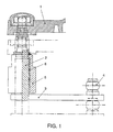
- Figure 1 shows the use of an axially unloaded shaft in normal operation for a Windshield wiper system of a motor vehicle.
- Wave 2 is not closer here Placed bearings 6 shown in the fixed receptacle 5.
- the fixed one Recording 5 is firmly connected to the vehicle, not shown here.
- the wave 2 is driven by a lever 3 and a ball head 4.
- Wiper arm 1 is on the end of the shaft 2 facing away from the vehicle.
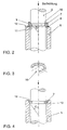
- Figure 2 shows the Spring washer 7 with a tapering surface 10 on the inner diameter again abuts the tapered surface 9 of the shaft 2.
- the spring ring 7 has at least one break 15 over its circumference and is based on its Surface 11 directly or via the washer 8 on the surface 12 of the receptacle 5.
- the spring ring 7 is with a tapering surface on the outer diameter 13, which bears against a tapering surface 14 of the receptacle 5. If the shaft 2 is suddenly loaded axially, the spring ring 7 is tapered by the Surfaces 13; 14 compressed and slides with the shaft through the receptacle 5th
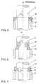
- FIG. 7 shows a variant with only one tapering surface 10.
- the spring ring is expanded by pressing the edge of the shoulder of shaft 2 on the tapered surface 10 instead.
- the angle ⁇ is approximately 30 ° in all variants.
Landscapes
- Engineering & Computer Science (AREA)
- Mechanical Engineering (AREA)
- General Engineering & Computer Science (AREA)
- Vibration Prevention Devices (AREA)
- Support Of The Bearing (AREA)
- Motor Or Generator Frames (AREA)
Description
Die Erfindung betrifft eine Vorrichtung zur axialen Fixierung einer axial im wesentlichen unbelasteten Welle in einer feststehenden Aufnahme mit einem Federring, der über seinen Umfang zumindest an einer Stelle eine Unterbrechung aufweist.The invention relates essentially to a device for axially fixing an axially unloaded shaft in a fixed receptacle with a spring ring that over its scope has an interruption at least at one point.
Eine solche Lagerung wird z. B. für eine Wischerwelle in einer Scheibenwischvorrichtung für Kraftfahrzeuge verwendet.Such storage is such. B. for a wiper shaft in a windshield wiper device used for motor vehicles.
In der europäischen Offenlegungsschrift EP 603 085 A1 wird eine Lagerung einer solchen Welle mit zwei Gleitlagern vorgeschlagen. Weiterhin werden elastische Mittel vorgeschlagen über die axiale Stöße gedämpft werden sollen, und damit eine Beschädigung der Wischerwelle bzw. des Wischerarms verhindert wird. Der mögliche Federweg ist dabei durch die Dicke und Elastizität der elastischen Mittel begrenzt.European patent application EP 603 085 A1 describes storage of such Proposed shaft with two plain bearings. Elastic means are also proposed should be damped over the axial shocks, and thus one Damage to the wiper shaft or wiper arm is prevented. The possible Travel is limited by the thickness and elasticity of the elastic means.
Eine weitere Lagerung ist in der deutschen Patentschrift DE 39 14 231 C2 beschrieben. Eine axiale Nachgiebigkeit wird dort jedoch nicht vorgeschlagen.Another storage is described in German patent DE 39 14 231 C2. However, axial compliance is not proposed there.
Bei keiner der oben genannten Lösungen ist eine axiale Nachgiebigkeit bei plötzlich auftretender axialer Beanspruchung vorgesehen. Insbesondere bei einer Verwendung einer derartigen Welle in einer Scheibenwischanlage eines Kraftfahrzeuges ist es wünschenswert, dass im Falle eines Verkehrsunfalles mit einem Fußgänger oder Radfahrer die Welle beim Aufprallen des Kopfes oder von Gliedmaßen zur Verringerung der Verletzungsgefahr nachgiebig gelagert ist bzw. durchrutschen kann.In none of the above solutions is an axial resilience in the event of sudden occurrence axial load provided. Especially when using a such a shaft in a windshield wiper system of a motor vehicle, it is desirable that in the event of a traffic accident involving a pedestrian or cyclist Wave when hitting the head or limbs to reduce the Risk of injury is resiliently stored or can slip.
Des weiteren ist aus der FR-A-2 668 442 eine Anordnung zur Lagerung einer axial im wesentlichen unbelasteten Welle in einer feststehenden Aufnahme vermittel zweier Gleitlager bekannt. Im Bereich zwischen diesen ist ein Ring mit einem Innendurchmesser größer als der Wellendurchmesser im Anordnungsbereich desselben angeordnet, wobei der Ring auf seiner der Welle zugewandten Seite mit einer sich in Richtung einer möglichen axialen Stoßbelastung verjüngenden koaxialen Fläche versehen ist. Mit dieser korrespondiert eine an der Welle in einem im Durchmesser vergrößerten Bereich ausgebildete, sich in der Stoßrichtung verjüngende Fläche. Bei einer Stoßbelastung wird die Welle axial in Richtung auf den Ring verbracht, und die beiden Flächen gelangen zur Anlage aneinander, wobei auf den Ring sowohl eine Kraftkomponente in axialer Richtung als auch eine solche in radialer Richtung ausgeübt wird. Dabei wird der an der Aufnahme anliegende Ring mit seinem äußeren Umfang gegen diese gedrückt, wodurch in Verbindung mit einer axialen Verschiebung der Welle und des Ringes Stoßenergie verzehrt wird.Furthermore, from FR-A-2 668 442 an arrangement for mounting an axially in the essentially unloaded shaft in a fixed receptacle by means of two Plain bearings known. In the area between these is a ring with a Inner diameter larger than the shaft diameter in the arrangement area of the same arranged, the ring on its side facing the shaft with a Direction of a possible axial impact tapering coaxial surface is provided. This corresponds to one on the shaft in one in diameter enlarged area formed, tapering in the direction of impact. at a shock load, the shaft is moved axially towards the ring, and the Both surfaces come into contact with each other, with both one on the ring Force component exerted in the axial direction as well as one in the radial direction becomes. The ring lying on the receptacle with its outer circumference pressed against this, which in conjunction with an axial displacement of the shaft and the ring's impact energy is consumed.
Erfindung liegt nun die Aufgabe zugrunde, eine Vorrichtung zur Fixierung einer axial im
wesentlichen unbelasteten Welle nach dem Oberbegriff des Anspruchs 1 so zu
gestalten, dass die Welle bei einer plötzlich auftretenden axialen Beanspruchung
durchrutscht.The invention is based on the object of a device for fixing an axially in the
essentially unloaded shaft according to the preamble of
Diese Aufgabe wird erfindungsgemäß durch die Merkmale des Anspruches 1 gelöst,
vorteilhafte Aus- und Weiterbildungen sind in den Unteransprüchen gegeben.This object is achieved by the features of
Die Erfindung besteht darin, dass die Vorrichtung einen an einer feststehenden Aufnahme für die Welle angeordneten Federring aufweist, der an seinem Umfang an einer Stelle unterbrochen ist und eine koaxiale, sich in axialer Richtung auf die Aufnahme zu verjüngende oder erweiternde Fläche aufweist, mit der dieser an einer an der Welle oder der Aufnahme ausgebildeten und mit dieser korrespondierenden Fläche anliegt. The invention consists in that the device is attached to a fixed one Recording for the shaft arranged spring ring, which on its circumference a point is interrupted and a coaxial, in the axial direction on the Recording to be tapered or widening surface with which this on a the shaft or the receptacle and with this corresponding surface is applied.
Bei einer plötzlich auftretenden Stoßbelastung in axialer Richtung weitet die Welle den Federring auf und rutscht durch den Federring und die Aufnahme oder sie drückt den Federring zusammen und rutscht mit diesem zusammen durch die Aufnahme. Ein besonders gutes Durchrutschvermögen wird erreicht, wenn sich die gegenüberliegenden verjüngenden oder erweiternden Flächenpaare in dem gleichen Winkel verjüngen oder erweitem. Eine genaue Zuordnung der Flächen ist in dem Ausführungsbeispiel beschrieben.In the event of a sudden shock load in the axial direction, the shaft widens the Spring ring on and slips through the spring ring and the receptacle or it presses Spring ring together and slides together with it through the receptacle. On Particularly good slip is achieved when the opposite ones tapering or widening surface pairs at the same angle or erweitem. A precise assignment of the areas is in the embodiment described.
Ein besonders guter Kompromiss zwischen axialer Fixierung und Durchrutschvermögen wird erreicht, wenn der Winkel α ca. 30° beträgt.A particularly good compromise between axial fixation and slippage is reached when the angle α is approx. 30 °.
Wird eine derartige Welle in einer Scheibenwischanlage eines Kraftfahrzeuges bei einem Unfall mit einem Fußgänger oder Radfahrer durch den Aufprall des Kopfes oder anderer Gliedmaßen stoßartig in axialer Richtung belastet, so rutscht die Welle durch. Das Verletzungsrisiko für den Fußgänger bzw. Radfahrer durch den Aufprall auf den Scheibenwischer ist damit verringert.Will such a shaft in a windshield wiper system of a motor vehicle an accident with a pedestrian or cyclist due to the impact of the head or other limbs are suddenly loaded in the axial direction, so the shaft slips. The risk of injury to pedestrians or cyclists from the impact on the The wiper is reduced.
Nachfolgend wird die Erfindung anhand eines Ausführungsbeispiels näher beschrieben. Die zugehörigen Zeichnungen zeigen:
Figur 1- Anordnung einer im Normalbetrieb axial unbelasteten Welle in einer Scheibenwischanlage eines Kraftfahrzeuges;
Figur 2- Federring mit sich verjüngendem Innendurchmesser und sich verjüngender Welle;
Figur 3- Federring mit sich verjüngendem Innendurchmesser;
Figur 4- Federring mit sich verjüngendem Außendurchmesser und Aufnahme mit sich verjüngendem Innendurchmesser;
Figur 5- Federring mit sich erweiterndem Durchmesser und Aufnahme mit sich erweiterndem Außendurchmesser;
Figur 6- Federring mit sich erweiterndem Außendurchmesser und Wellenabsatz mit sich erweiterndem Innendurchmesser;
Figur 7- Federring mit sich verjüngendem Innendurchmesser und anliegendem Wellenabsatz.
- Figure 1
- Arrangement of a shaft axially unloaded in normal operation in a windshield wiper system of a motor vehicle;
- Figure 2
- Spring washer with tapered inner diameter and tapered shaft;
- Figure 3
- Spring washer with tapered inner diameter;
- Figure 4
- Spring washer with tapered outer diameter and seat with tapered inner diameter;
- Figure 5
- Spring ring with expanding diameter and receptacle with expanding external diameter;
- Figure 6
- Spring washer with expanding outer diameter and shaft shoulder with expanding inner diameter;
- Figure 7
- Spring washer with a tapering inner diameter and a fitted shaft shoulder.
Figur 1 zeigt die Verwendung einer im Normalbetrieb axial unbelasteten Welle für eine
Scheibenwischanlage einer Kraftfahrzeuges. Die Welle 2 ist in hier nicht näher
dargestellten Gleitlagern 6 in der feststehenden Aufnahme 5 gelagert. Die feststehende
Aufnahme 5 ist fest mit dem hier nicht dargestellten Fahrzeug verbunden. Die Welle 2
wird über einen Hebel 3 und einem Kugelkopf 4 angetrieben. Der Wischerarm 1 ist an
dem dem Fahrzeug abgewandten Ende der Welle 2 angeordnet. Figur 2 zeigt den
Federring 7 mit einer sich am inneren Durchmesser verjüngenden Fläche 10, die
wiederum an der sich verjüngenden Fläche 9 der Welle 2 anliegt. Der Federring 7 weist
zumindest eine Unterbrechung 15 über seinen Umfang auf und stützt sich über seine
Fläche 11 direkt oder über die Unterlegscheibe 8 auf der Fläche 12 der Aufnahme 5 ab.
Bei einer plötzlich auftretenden axialen Stoßbelastung, wie z. B. das Auftreffen eines
Armes oder eines Kopfes von einem Fußgänger oder Radfahrer bei einem
Verkehrsunfall, so wird der Federring 7 durch das Ineinandergreifen der sich
verjüngenden Fläche 9; 10 aufgeweitet, und die Welle 2 rutscht durch den Federring 7
und die Aufnahme 5. Die Position nach dem Durchrutschen ist strichpunktiert in Figur 1
dargestellt.Figure 1 shows the use of an axially unloaded shaft in normal operation for a
Windshield wiper system of a motor vehicle.
In Figur 4 ist der Federring 7 mit einer sich am äußeren Durchmesser verjüngenden Fläche
13, die an einer sich verjüngenden Fläche 14 der Aufnahme 5 anliegt dargestellt.
Wird die Welle 2 plötzlich axial belastet, so wird der Federring 7 durch die sich verjüngenden
Flächen 13; 14 zusammengedrückt und rutscht mit der Welle durch die Aufnahme
5.In Figure 4, the
In Figur 5 ist der Federring 7 mit einer sich in Stoßrichtung erweiternden Fläche 16 des
Innendurchmessers dargestellt. Die sich erweiternde Fläche 16 liegt an einer sich erweiternden
Fläche 17 des Außendurchmessers der Aufnahme 5 an. Bei einer
Stoßbelastung in Pfeilrichtung wird der Federring 7 aufgeweitet und die Welle 2 rutscht
durch den Federring 7 und die Aufnahme 5 hindurch.In Figure 5, the
In Figur 6 wird der Federring 7 bei einer Belastung in Pfeilrichtung durch das Übereinandergreifen
der sich erweiternden Flächen 18; 19 zusammengedrückt und rutscht
dadurch mit der Welle durch die Aufnahme 5. In FIG. 6, the
In Figur 7 ist eine Variante mit nur einer sich verjüngenden Fläche 10 dargestellt. Hier
findet die Aufweitung des Federringes durch Druck der Kante des Absatzes der Welle 2
auf die sich verjüngende Fläche 10 statt.FIG. 7 shows a variant with only one
Der Winkel α beträgt bei allen Varianten ca. 30°. The angle α is approximately 30 ° in all variants.
- 11
- Wischerarmwiper
- 22
- Wellewave
- 33
- Hebellever
- 44
- Kugelkopfball head
- 55
- Aufnahmeadmission
- 66
- Lagerung mit DichtringenStorage with sealing rings
- 77
- Federringspring washer
- 88th
- Unterlegscheibewasher
- 99
- sich verjüngende Flächetapered surface
- 1010
- sich verjüngende Flächetapered surface
- 1111
- Flächearea
- 1212
- Flächearea
- 1313
- sich verjüngende Flächetapered surface
- 1414
- sich verjüngende Flächetapered surface
- 1515
- Unterbrechung des UmfangesInterruption of scope
- 1616
- sich erweiternde Flächeexpanding area
- 1717
- sich erweiternde Flächeexpanding area
- 1818
- sich erweiternde Flächeexpanding area
- 1919
- sich erweiternde Flächeexpanding area
- αα
- Winkelangle
Claims (7)
- Device for axially fixing a shaft (2), which is essentially unstressed axially, in a fixed holder (5) with a spring ring (7), characterized in that the spring ring (7) has an interruption on its circumference (15) at a point on its circumference and has a coaxial surface (16; 18) which can taper (10; 13) or widen in the axial direction at an angle α to the holder (5) and with which the said ring (7) bears against a surface (9; 14; 17; 19) which is formed on the shaft (2) or on the holder (5) and corresponds with the surface (10; 13; 16; 18).
- Device according to Claim 1, characterized in that the angle α is essentially 30°.
- Device according to Claim 1, characterized in that the spring ring (7) is supported on the holder (5), and in that the tapering surface (10) is formed on that side of the spring ring (7) which faces the axis of the shaft (2) and the surface (9) corresponding with the said surface (10) is formed on the circumference of the shaft (2).
- Device according to Claim 1, characterized in that the spring ring (7) is arranged in an encircling groove formed on the shaft (2), and in that the tapering surface (13) is formed on that side of the spring ring (7) which faces away from the axis of the shaft (2) and the surface (14) corresponding with the said surface is formed on the holder (5).
- Device according to Claim 1, characterized in that the spring ring (7) is supported on a step formed on the shaft (2) on an encircling bearing shoulder which faces the holder (5), and in that the widening surface (16) is formed on that side of the spring ring (7) which faces the axis of the shaft (2) and the surface (17) corresponding with the said surface is formed on the holder.
- Device according to Claim 1, characterized in that the spring ring (7) is supported on the holder (5), and in that the widening surface (18) is formed on that side of the spring ring (7) which faces away from the axis of the shaft (2) and the surface (19) corresponding with the said surface is formed on an undercut formed on the shaft (2).
- Use of a device according to one of Claims 1 to 4 in a window-wiping device of a motor vehicle.
Applications Claiming Priority (2)
| Application Number | Priority Date | Filing Date | Title |
|---|---|---|---|
| DE19618873 | 1996-05-10 | ||
| DE19618873 | 1996-05-10 |
Publications (3)
| Publication Number | Publication Date |
|---|---|
| EP0806329A2 EP0806329A2 (en) | 1997-11-12 |
| EP0806329A3 EP0806329A3 (en) | 1998-09-02 |
| EP0806329B1 true EP0806329B1 (en) | 2002-09-18 |
Family
ID=7793954
Family Applications (1)
| Application Number | Title | Priority Date | Filing Date |
|---|---|---|---|
| EP97105514A Expired - Lifetime EP0806329B1 (en) | 1996-05-10 | 1997-04-03 | Device to support an axially unloaded shaft |
Country Status (2)
| Country | Link |
|---|---|
| EP (1) | EP0806329B1 (en) |
| DE (1) | DE59708231D1 (en) |
Cited By (1)
| Publication number | Priority date | Publication date | Assignee | Title |
|---|---|---|---|---|
| CN102652082A (en) * | 2009-12-17 | 2012-08-29 | 罗伯特·博世有限公司 | Windshield wiper device |
Families Citing this family (24)
| Publication number | Priority date | Publication date | Assignee | Title |
|---|---|---|---|---|
| EP0916559B1 (en) | 1997-10-22 | 2004-12-29 | Nissan Motor Co., Ltd. | Wiper device for vehicle |
| ES2260928T3 (en) * | 1998-01-29 | 2006-11-01 | Robert Bosch Gmbh | WINDSHIELD CLEANING DEVICE. |
| US6317918B1 (en) * | 1998-04-24 | 2001-11-20 | Honda Giken Kogyo Kabushiki Kaisha | Windshield wiper device for vehicle |
| JPH11334539A (en) * | 1998-05-22 | 1999-12-07 | Honda Motor Co Ltd | Vehicle wiper device |
| EP1033295A3 (en) * | 1999-03-03 | 2002-05-15 | Trico Products (Dunstable) Limited | Windscreen wiper assembly |
| GB2347340A (en) * | 1999-03-03 | 2000-09-06 | Trico Products | Windscreen wiper with safety system to reduce spearing danger |
| DE19914120A1 (en) | 1999-03-27 | 2000-09-28 | Volkswagen Ag | Fastening arrangement for a device on a vehicle body |
| JP2000344058A (en) | 1999-06-04 | 2000-12-12 | Asmo Co Ltd | Wiper pivot |
| JP3564007B2 (en) * | 1999-08-05 | 2004-09-08 | 株式会社ミツバ | Vehicle wiper device |
| WO2002018195A1 (en) * | 2000-08-29 | 2002-03-07 | Klaus Schorn | Vehicle body |
| GB0025520D0 (en) * | 2000-10-18 | 2000-11-29 | Trico Products Dunstable Ltd | Safety windscreen |
| NL1020197C2 (en) * | 2002-03-18 | 2003-09-19 | Tno | Windscreen wiper, has rotary shaft which is freely movable in its axial direction |
| DE10255774B4 (en) | 2002-11-29 | 2017-02-02 | Robert Bosch Gmbh | Windscreen wiper device, in particular for a motor vehicle |
| DE10309942B4 (en) * | 2003-03-07 | 2014-11-13 | Robert Bosch Gmbh | A windscreen wiper device |
| DE10320933A1 (en) * | 2003-05-09 | 2004-12-02 | Volkswagen Ag | Impact-soft mounting of a shaft on a vehicle |
| FR2859961B1 (en) | 2003-09-19 | 2011-04-22 | Volkswagen Ag | FLEXIBLE COUPLING OF A DRIVE SHAFT OF A WINDSCREEN WIPER ON A VEHICLE |
| DE10352468A1 (en) * | 2003-11-07 | 2005-06-02 | Robert Bosch Gmbh | Windscreen wiper device, in particular for a motor vehicle |
| FR2863990B1 (en) * | 2003-12-23 | 2006-02-24 | Valeo Systemes Dessuyage | ARRANGEMENT FOR FASTENING A WIPING MECHANISM FOR ERASING THE DRIVE SHAFT IN THE EVENT OF A SHOCK |
| DE102005027533B4 (en) * | 2005-06-15 | 2009-03-19 | Audi Ag | Windscreen wiper system for a motor vehicle |
| DE102005035088A1 (en) | 2005-07-27 | 2007-02-01 | Robert Bosch Gmbh | Windscreen wiper device, in particular for a motor vehicle |
| DE102006013541B4 (en) * | 2006-03-24 | 2011-05-05 | Audi Ag | Windscreen wiper system for motor vehicles |
| CZ2006562A3 (en) * | 2006-09-08 | 2008-03-19 | Pal International A. S. | Device for attaching shafts of vehicle wiper assembly blades |
| DE102015221741A1 (en) * | 2015-11-05 | 2017-05-11 | Robert Bosch Gmbh | Windscreen wiper device, in particular for a motor vehicle |
| FR3063315B1 (en) * | 2017-02-27 | 2021-05-14 | Valeo Systemes Dessuyage | CASING OF A GEAREDUCER GROUP ASSOCIATED WITH AN OUTPUT SHAFT SUITABLE TO MOVE A WIPING SYSTEM FOR A GLASS SURFACE OF A MOTOR VEHICLE |
Family Cites Families (4)
| Publication number | Priority date | Publication date | Assignee | Title |
|---|---|---|---|---|
| FR2453756A1 (en) * | 1979-02-22 | 1980-11-07 | Peugeot | ARRANGEMENT OF A WINDSCREEN WIPER ON A MOTOR VEHICLE |
| GB2217399B (en) * | 1988-04-15 | 1992-02-26 | Austin Rover Group | A seal |
| FR2668442B1 (en) * | 1990-10-30 | 1994-11-18 | Nacam | STEERING COLUMN WITH ENERGY ABSORBING DEVICE. |
| FR2701000B1 (en) * | 1993-02-02 | 1995-04-21 | Nacam | Additional energy absorption system for a motor vehicle steering column. |
-
1997
- 1997-04-03 EP EP97105514A patent/EP0806329B1/en not_active Expired - Lifetime
- 1997-04-03 DE DE59708231T patent/DE59708231D1/en not_active Expired - Lifetime
Cited By (2)
| Publication number | Priority date | Publication date | Assignee | Title |
|---|---|---|---|---|
| CN102652082A (en) * | 2009-12-17 | 2012-08-29 | 罗伯特·博世有限公司 | Windshield wiper device |
| CN102652082B (en) * | 2009-12-17 | 2016-02-10 | 罗伯特·博世有限公司 | Wiper device |
Also Published As
| Publication number | Publication date |
|---|---|
| DE59708231D1 (en) | 2002-10-24 |
| EP0806329A2 (en) | 1997-11-12 |
| EP0806329A3 (en) | 1998-09-02 |
Similar Documents
| Publication | Publication Date | Title |
|---|---|---|
| EP0806329B1 (en) | Device to support an axially unloaded shaft | |
| EP1263632B1 (en) | Wiper system | |
| EP1299652B1 (en) | Connecting element | |
| DE10106915C2 (en) | suspension arrangement | |
| DE2326018C3 (en) | Ball joint, in particular for steering linkages in motor vehicles | |
| EP2414180B1 (en) | Elastomer articulation | |
| DE69507262T2 (en) | GRIP AND DAMPING DEVICE APPLIED TO PERCENTRIC TOOLS | |
| DE19644968B4 (en) | Bicycle steering arrangement | |
| EP0651177B1 (en) | Oscillation damper | |
| EP1040972B1 (en) | Fixing arrrangement of a device on a vehicle body | |
| DE4209835A1 (en) | BALL CONNECTION | |
| DE19859238A1 (en) | Motor vehicle seat has damping element as separate component and connected to seat and longitudinal adjustment rail by element formed by threaded rod, rotatable nut and sleeve-form component | |
| DE602004002469T2 (en) | SHOCK ABSORBER STOP FOR A MOTOR VEHICLE | |
| EP1926641A1 (en) | Windscreen wiper device, in particular for a motor vehicle | |
| EP1458596A1 (en) | Fixation of a wiper system | |
| DE4419042C2 (en) | shock absorber | |
| DE102016200307A1 (en) | Spring plate for a vibration damper | |
| DE60302069T2 (en) | ANGLE MOUNTING ACTUATOR AND GEAR WITH MOUNTING FOR IT | |
| DE102007021228B4 (en) | Shock absorber - swivel bearing connection of a wheel suspension of a motor vehicle | |
| DE4323551C2 (en) | Windscreen wiper device for vehicles | |
| DE10343572A1 (en) | Flexible assembly for driving shaft of windshield wiper, has bushings displaced, along with shaft, in axial direction when shaft is subjected to collision, and clutch spring arranged coaxially to shaft | |
| DE19946923B4 (en) | Hub cover for a wheel bearing, preferably for a commercial vehicle wheel bearing | |
| DE3610283C2 (en) | ||
| DE10343573A1 (en) | Flexible assembly for driving shaft of windshield wiper, has bushings displaced, along with shaft, in axial direction when shaft is subjected to collision, and clutch spring arranged coaxially to shaft | |
| EP1567396A1 (en) | Window-wiping device, particularly for a motor vehicle |
Legal Events
| Date | Code | Title | Description |
|---|---|---|---|
| PUAI | Public reference made under article 153(3) epc to a published international application that has entered the european phase |
Free format text: ORIGINAL CODE: 0009012 |
|
| AK | Designated contracting states |
Kind code of ref document: A2 Designated state(s): DE ES FR GB IT SE |
|
| PUAL | Search report despatched |
Free format text: ORIGINAL CODE: 0009013 |
|
| AK | Designated contracting states |
Kind code of ref document: A3 Designated state(s): DE ES FR GB IT SE |
|
| 17P | Request for examination filed |
Effective date: 19990302 |
|
| 17Q | First examination report despatched |
Effective date: 20010316 |
|
| GRAG | Despatch of communication of intention to grant |
Free format text: ORIGINAL CODE: EPIDOS AGRA |
|
| GRAG | Despatch of communication of intention to grant |
Free format text: ORIGINAL CODE: EPIDOS AGRA |
|
| GRAH | Despatch of communication of intention to grant a patent |
Free format text: ORIGINAL CODE: EPIDOS IGRA |
|
| GRAH | Despatch of communication of intention to grant a patent |
Free format text: ORIGINAL CODE: EPIDOS IGRA |
|
| GRAA | (expected) grant |
Free format text: ORIGINAL CODE: 0009210 |
|
| AK | Designated contracting states |
Kind code of ref document: B1 Designated state(s): DE ES FR GB IT SE |
|
| PG25 | Lapsed in a contracting state [announced via postgrant information from national office to epo] |
Ref country code: IT Free format text: LAPSE BECAUSE OF FAILURE TO SUBMIT A TRANSLATION OF THE DESCRIPTION OR TO PAY THE FEE WITHIN THE PRESCRIBED TIME-LIMIT;WARNING: LAPSES OF ITALIAN PATENTS WITH EFFECTIVE DATE BEFORE 2007 MAY HAVE OCCURRED AT ANY TIME BEFORE 2007. THE CORRECT EFFECTIVE DATE MAY BE DIFFERENT FROM THE ONE RECORDED. Effective date: 20020918 Ref country code: GB Free format text: LAPSE BECAUSE OF FAILURE TO SUBMIT A TRANSLATION OF THE DESCRIPTION OR TO PAY THE FEE WITHIN THE PRESCRIBED TIME-LIMIT Effective date: 20020918 |
|
| REG | Reference to a national code |
Ref country code: GB Ref legal event code: FG4D Free format text: NOT ENGLISH |
|
| REF | Corresponds to: |
Ref document number: 59708231 Country of ref document: DE Date of ref document: 20021024 |
|
| PG25 | Lapsed in a contracting state [announced via postgrant information from national office to epo] |
Ref country code: SE Free format text: LAPSE BECAUSE OF FAILURE TO SUBMIT A TRANSLATION OF THE DESCRIPTION OR TO PAY THE FEE WITHIN THE PRESCRIBED TIME-LIMIT Effective date: 20021218 |
|
| ET | Fr: translation filed | ||
| GBV | Gb: ep patent (uk) treated as always having been void in accordance with gb section 77(7)/1977 [no translation filed] |
Effective date: 20020918 |
|
| PG25 | Lapsed in a contracting state [announced via postgrant information from national office to epo] |
Ref country code: ES Free format text: LAPSE BECAUSE OF FAILURE TO SUBMIT A TRANSLATION OF THE DESCRIPTION OR TO PAY THE FEE WITHIN THE PRESCRIBED TIME-LIMIT Effective date: 20030328 |
|
| PLBE | No opposition filed within time limit |
Free format text: ORIGINAL CODE: 0009261 |
|
| STAA | Information on the status of an ep patent application or granted ep patent |
Free format text: STATUS: NO OPPOSITION FILED WITHIN TIME LIMIT |
|
| 26N | No opposition filed |
Effective date: 20030619 |
|
| PGFP | Annual fee paid to national office [announced via postgrant information from national office to epo] |
Ref country code: DE Payment date: 20130430 Year of fee payment: 17 |
|
| PGFP | Annual fee paid to national office [announced via postgrant information from national office to epo] |
Ref country code: FR Payment date: 20130612 Year of fee payment: 17 |
|
| REG | Reference to a national code |
Ref country code: DE Ref legal event code: R119 Ref document number: 59708231 Country of ref document: DE |
|
| REG | Reference to a national code |
Ref country code: FR Ref legal event code: ST Effective date: 20141231 |
|
| PG25 | Lapsed in a contracting state [announced via postgrant information from national office to epo] |
Ref country code: DE Free format text: LAPSE BECAUSE OF NON-PAYMENT OF DUE FEES Effective date: 20141101 |
|
| REG | Reference to a national code |
Ref country code: DE Ref legal event code: R119 Ref document number: 59708231 Country of ref document: DE Effective date: 20141101 |
|
| PG25 | Lapsed in a contracting state [announced via postgrant information from national office to epo] |
Ref country code: FR Free format text: LAPSE BECAUSE OF NON-PAYMENT OF DUE FEES Effective date: 20140430 |