EP0806137A2 - Spinning reel - Google Patents
Spinning reel Download PDFInfo
- Publication number
- EP0806137A2 EP0806137A2 EP97303033A EP97303033A EP0806137A2 EP 0806137 A2 EP0806137 A2 EP 0806137A2 EP 97303033 A EP97303033 A EP 97303033A EP 97303033 A EP97303033 A EP 97303033A EP 0806137 A2 EP0806137 A2 EP 0806137A2
- Authority
- EP
- European Patent Office
- Prior art keywords
- rotor
- spinning reel
- guard
- guard arm
- reel
- Prior art date
- Legal status (The legal status is an assumption and is not a legal conclusion. Google has not performed a legal analysis and makes no representation as to the accuracy of the status listed.)
- Granted
Links
Images

Classifications
-
- A—HUMAN NECESSITIES
- A01—AGRICULTURE; FORESTRY; ANIMAL HUSBANDRY; HUNTING; TRAPPING; FISHING
- A01K—ANIMAL HUSBANDRY; AVICULTURE; APICULTURE; PISCICULTURE; FISHING; REARING OR BREEDING ANIMALS, NOT OTHERWISE PROVIDED FOR; NEW BREEDS OF ANIMALS
- A01K89/00—Reels
- A01K89/01—Reels with pick-up, i.e. with the guiding member rotating and the spool not rotating during normal retrieval of the line
- A01K89/01121—Frame details
-
- A—HUMAN NECESSITIES
- A01—AGRICULTURE; FORESTRY; ANIMAL HUSBANDRY; HUNTING; TRAPPING; FISHING
- A01K—ANIMAL HUSBANDRY; AVICULTURE; APICULTURE; PISCICULTURE; FISHING; REARING OR BREEDING ANIMALS, NOT OTHERWISE PROVIDED FOR; NEW BREEDS OF ANIMALS
- A01K89/00—Reels
- A01K89/015—Reels with a rotary drum, i.e. with a rotating spool
-
- A—HUMAN NECESSITIES
- A01—AGRICULTURE; FORESTRY; ANIMAL HUSBANDRY; HUNTING; TRAPPING; FISHING
- A01K—ANIMAL HUSBANDRY; AVICULTURE; APICULTURE; PISCICULTURE; FISHING; REARING OR BREEDING ANIMALS, NOT OTHERWISE PROVIDED FOR; NEW BREEDS OF ANIMALS
- A01K89/00—Reels
- A01K89/01—Reels with pick-up, i.e. with the guiding member rotating and the spool not rotating during normal retrieval of the line
-
- A—HUMAN NECESSITIES
- A01—AGRICULTURE; FORESTRY; ANIMAL HUSBANDRY; HUNTING; TRAPPING; FISHING
- A01K—ANIMAL HUSBANDRY; AVICULTURE; APICULTURE; PISCICULTURE; FISHING; REARING OR BREEDING ANIMALS, NOT OTHERWISE PROVIDED FOR; NEW BREEDS OF ANIMALS
- A01K89/00—Reels
- A01K89/02—Brake devices for reels
- A01K89/027—Brake devices for reels with pick-up, i.e. for reels with the guiding member rotating and the spool not rotating during normal retrieval of the line
-
- A—HUMAN NECESSITIES
- A01—AGRICULTURE; FORESTRY; ANIMAL HUSBANDRY; HUNTING; TRAPPING; FISHING
- A01K—ANIMAL HUSBANDRY; AVICULTURE; APICULTURE; PISCICULTURE; FISHING; REARING OR BREEDING ANIMALS, NOT OTHERWISE PROVIDED FOR; NEW BREEDS OF ANIMALS
- A01K89/00—Reels
- A01K89/015—Reels with a rotary drum, i.e. with a rotating spool
- A01K89/0155—Antibacklash devices
-
- A—HUMAN NECESSITIES
- A01—AGRICULTURE; FORESTRY; ANIMAL HUSBANDRY; HUNTING; TRAPPING; FISHING
- A01K—ANIMAL HUSBANDRY; AVICULTURE; APICULTURE; PISCICULTURE; FISHING; REARING OR BREEDING ANIMALS, NOT OTHERWISE PROVIDED FOR; NEW BREEDS OF ANIMALS
- A01K89/00—Reels
- A01K89/015—Reels with a rotary drum, i.e. with a rotating spool
- A01K89/0183—Drive mechanism details
Definitions
- the present invention relates to a reel, and particularly to a spinning reel mounted on a fishing rod.
- the conventional spinning reel comprises a reel body which is equipped with a mounting leg for the rod, a rotor that is rotatably supported on the reel body, and a spool which is disposed forward of the rotor, around whose outside surface a fishing line is wound.
- the rotor has a first rotor arm and a second rotor arm which are disposed facing each other on opposite sides of a rotating shaft.
- a bail is pivotally supported at the distal ends of the two arms via bail support members. The distal end of one of the bail support members is provided with a line roller. When the line is retrieved, the line is guided onto the outside surface of the spool by the bail and the line roller.
- Some spinning reels of this kind are provided with a braking mechanism that brakes the rotation of the rotor when it reverses (when it rotates in the line release direction).
- the braking mechanism is normally operated using a pivoting brake lever provided on the mounting leg of the reel body. In this type of spinning reel, the brake lever is pivoted towards the rod using the hand which holds the rod, thereby braking the rotor when it reverses.
- a spinning reel for mounting on a fishing rod which comprises a reel body, a rotor, a spool, and a guard arm.
- the reel body includes a reel body section and a mounting leg member with a rod mounting member at its distal end for attachment to a fishing rod.
- the guard arm is disposed between the rod mounting member and the rotor.
- the guard arm is disposed between the rotor and the rod mounting member, thereby making it difficult for the fingers holding the rod to come into contact with the rotor, even when the rotor is rotating.
- the guard arm is cantilevered on the mounting leg member.
- the guard arm is securely held in place thereby.
- the inventive spinning reel further includes a braking mechanism for braking the rotor when the rotor reverses, and a brake lever for operating the braking mechanism.
- the brake lever is pivotally supported on the reel body section and has a distal end that extends between the guard arm and the rod attachment member. Since the guard arm is disposed between the distal end of the brake lever and the rotor, it is difficult for the fingers used to hold the rod and operate the brake lever to come into contact with the rotor, even when the brake lever is operated using the same fingers that hold the rod.
- the foregoing guard arm is cantilevered on the leg mounting member or on the brake lever. In the latter particular embodiment, since the guard arm moves together with the brake lever, the finger used to operate the brake lever is reliably protected.
- the guard arm comprises a guard member and a mounting member that supports the guard member. More particularly, at least the guard member is comprised of an elastomer, preferably a soft elastomer. This helps to prevent damage to the rotor if the guard member should happen to contact the rotor. The noise produced by contact serves as a warning.
- the rotor and the guard arm have respective distal ends, and the distal end of the guard arm extends to the vicinity of (i.e., adjacent to) the distal end of the rotor. Substantially the entire rotating section of the rotor is covered thereby, preventing the fingers which hold the pole from coming into contact with the rotor.
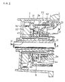
- FIG. 1 is a sectional side elevational view of a first preferred embodiment of the present invention.
- FIG. 2 is a cross sectional view of the brake mechanism thereof.
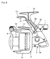
- FIG. 3 is a side elevational view of another preferred embodiment in which the guard arm is cantilevered from a brake lever.
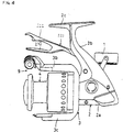
- FIG. 4 is a side elevational view of another preferred embodiment in which the guard arm extends to the distal end of the rotor.
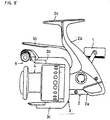
- FIG. 5 is a side elevational view of another preferred embodiment in which the spinning reel does not include a brake mechanism.
- a first preferred embodiment of the inventive spinning reel as illustrated in Fig. 1 comprises a reel body 2 with a rotating handle 1, a rotor 3 which is rotatably supported at the front of the reel body 2, and a spool 4 located at the front of the aforementioned rotor for reeling up a fishing line.
- the reel body 2 has a reel body section 2a, and a mounting leg member 2b, formed on the top of the reel body section 2a, for mounting the spinning reel onto a fishing rod.
- a rod attachment member 2c which extends forward and back preferably is provided to the distal end of the mounting leg member 2b.
- the interior of the reel body section 2a contains a rotor drive mechanism (not shown) for rotating the rotor 3, a level wind mechanism (not shown) for moving the spool in the longitudinal direction along the axis of rotation so that the line is wound evenly around the spool 4, and a rotor brake mechanism 6 for braking the rotor.
- the rotor drive and level wind mechanisms can be any such mechanisms known to those skilled in the art.
- the rotor 3 has a cylindrical member 3a, and a first rotor arm 3b and second rotor arm 3c which are disposed facing each other at the sides of the cylindrical member 3a.
- a boss section 3f provided with a through hole 3e is formed in the center of the front wall 3d of the cylindrical member 3a.
- the spool shaft 8 and a pinion gear 12 are passed through the through hole 3e.
- the pinion gear 12 meshes with a master gear (not shown) attached to the rotating shaft (not shown) of the handle 1.
- a first bail support member 9b is pivotally attached to the first rotor arm 3b.
- a line roller 9a that is used to guide the fishing line to the spool 4 is mounted on the tip of the first bail support member 9b.
- a second bail support member 9c is pivotally attached to the second rotor arm 3c.
- a pivotable bail 9 is located between the second bail support member 3c and the line roller 9a on the tip of the first bail support member 9b.
- the spool 4 is located between the first rotor arm 3b and the second rotor arm 3c of the rotor 3, and is mounted on the distal end of the spool shaft 8 via a drag mechanism (not shown).
- the spool 4 has a spooling drum 4a on whose outside surface the fishing line is spooled, an integrally formed skirt section 4b located to the rear of the spooling drum 4a, and a flange section 4c affixed to the front end of the spooling drum 4a.
- the spool shaft 8 can be moved in the longitudinal direction by the level wind mechanism.
- the rotor braking mechanism 6 has a brake member 20 and a brake lever 21 for operating the brake member.
- the brake member 20 comprises a brake member body 31 which is braked using the brake lever 21 and a one-way clutch 32 which rotates the brake member body 31 only in association with rotation of the rotor 3 in the release direction.
- the brake lever 21 is supported in pivoting fashion on the reel body section 2a by a support shaft 33. It is energized in the counterclockwise direction in Fig. 1 by an energizing component (not shown).
- the brake lever 21 has a control lever section 22 which curves away from the support shaft 33 and projects diagonally upward.
- a braking action member 23 is provided at the distal end which curves away from the support shaft 33 and projects diagonally downward.
- the distal end of the control lever section 22 is located in proximity to the rod attachment member 2c.
- the brake member body 31 comprises a brake cylinder 40 disposed within the rim of the rotor 3 and concentric with the rotor 3, a rotating cylinder 41 which supports the brake cylinder 40 in rocking, non-rotating fashion, and a brake shoe 42 attached to the reel body section 2a.
- the brake cylinder 40 takes the form of a bottomed cylinder; the distal end of its outside rim 40a is disposed between the brake shoe 42 and the braking action member 23 of the brake lever 30.
- the brake cylinder 40 has at its center a support surface 40c that bends inward.
- the support surface 40c takes the form of a cylinder.
- the bottom surface 40b of the brake cylinder 40 is provided with a cross-shaped engagement groove 43. The engagement groove 43 extend to the end of the support surface 40c.
- the rotating cylinder 41 is supported by the one-way clutch 32 in such a way that its front end rotates in tandem with rotation of the rotor 3 in the line release direction, while the rotational force of the rotor 3 is prevented from acting upon it when the line is reeled in. Its basal end is rotatably supported on the reel body section 2a by a bearing 44.
- An adjustable joint member 45 for supporting the support surface 40c is provided to the outside surface of the rim in the middle of the rotating cylinder 41.
- the adjustable joint member 45 comprises a rotating ring section 45a which screws onto the rotating cylinder 41 and whose outside surface has a spherical portion, and four solid cylindrical engagement protrusions 45b which project outward in a cross shape from the outside surface of the rotating ring section 45a. These four solid cylindrical engagement protrusions 45b engage the engagement groove 43, and the support face 40c is supported on the rotating ring section 45a, whereby the brake cylinder 40 is support in rocking, non-rotating fashion on the rotating cylinder 41.
- a pair of spring bearing rings 46 are disposed on both sides of the rotating ring section 45a. in contact with it.
- a conical coil spring 47 is disposed in the compressed state between the right spring bearing ring 46 and the bearing 44 and between the left spring bearing ring 46 and the and the one-way clutch 32 in order to maintain the distal end of the brake cylinder 40 in the desired attitude, such that it does not contact the brake shoe 42 and the braking action member 30b of the brake lever 30.
- the brake cylinder 40 is supported in rocking, non-rotating fashion on the rotating cylinder 41.
- the brake cylinder 40 tilts to the position indicated by the broken lines in Fig. 2. Since the brake cylinder 40 is supported in rocking fashion on the rotating cylinder 41, the rotating cylinder 41 and pinion gear 12 are not subjected to a bending moment during braking, preventing chafing. Rotation of the rotor 3 proceeds unaffected, preventing rotation from becoming heavy.
- the one-way clutch 32 is of a freely-rotating outer ring type, wherein an outside ring is affixed to the cylindrical section of the rotor 3 and an inner ring is affixed to the rim at the distal end of the rotating cylinder 41.
- This one-way clutch 32 transmits the rotational force of the rotor 3 to the rotating cylinder 41 only when the rotor rotates in the line release direction.
- rotation of the rotating cylinder 41 enabling braking the braking mechanism 6 is possible only when the rotor 3 is rotating in the line release direction.
- the rotating cylinder 41 does not rotate, and braking by the rotor braking mechanism 6 is disabled.
- a guard arm 10 which projects further forward than the control lever section 22, is disposed between the control lever section 22 and the rotor arms 3b and 3c of the rotor 3.
- the guard arm 10 has a bar-shaped guard member 15 and a mounting member 16 that supports the guard member 15.
- the guard member 15 is comprised of an elastomer such as urethane rubber.
- Guard member 15 can also be comprised of a non-elastomeric material such as nylon.
- Guard member 15 is disposed substantially parallel to the spool shaft 8.
- the support member 16 is a wire-like member bent into a U-shape at its distal end; its basal end is supported in cantilever fashion on the mounting leg member 2b, straddling the control lever section 22.
- the guard member 15 is integrally formed on the distal end side of the support member 16.
- the bail 9 is moved to the retrieve position.
- the rotational force is transmitted to the pinion gear 12 via the rotating handle shaft and the master gear.
- the rotational force that has been transmitted to the pinion gear 12 is in turn transmitted to the rotor 3 via the front end of the pinion gear, whereupon the rotor 3 rotates in the retrieve direction, so the rotational force is not transmitted to the rotating cylinder 41 by the one-way clutch 32, as discussed earlier.
- the pinion gear 12 rotates, its rotation is transmitted to the level wind mechanism by an intermediate gear (not shown).
- the spool shaft 8 undergoes reciprocating motion in the longitudinal direction so that the line is wound evenly on the spool 4. Since the rotor 3 rotates during this time, and the guard arm 10 is disposed between the brake lever 21 and the rotor 3, the fingers which hold the rod do not come into contact with the rotor 3 even when the reel operates as the rod is held.
- Grasping the control lever section 22 of the brake lever 21 together with the rod and moving it towards the rod attachment member 2c causes the braking action member 23 to press against the inside surface of the distal end of the outside rim 40a of the brake cylinder 40, thereby inclining the brake cylinder 40 to the position indicated by the broken lines in Fig. 2, pressing the outside surface of the distal end of the outside rim 40a against the brake shoe 42. Braking force is applied to the reversing rotor 3 thereby.
- the braking force can be adjusted, allowing the rotation of the rotor 3 to be adjusted to the desired level. Since the brake cylinder 40 is supported in rocking fashion on the rotating cylinder 41 by the adjustable joint member 45, force which would cause chafing is not applied to the pinion gear 12, so rotation of the rotor 3 does not become heavy. Since a freely-rotating outer ring type one-way clutch 32 is used, the contact force between the rotating roller 52 and the outside ring 50 increases at higher rotation speed, so the initial braking is held at a stable level even if the rotor 3 should reverse and rotate at high speed.
- a guard arm 110 is supported at its basal end in cantilever fashion by a brake lever 121, as depicted in Fig. 3, is also possible.
- the guard arm 110 pivots together with the brake lever 121, thereby reliably protecting the finger used to operate the control lever section 122.
- FIG. 4 Another embodiment, illustrated in Fig. 4, includes a guard arm 210 which extends to the vicinity of the bail 9 at the distal end of the rotor 3.
- the control lever section 222 of the brake lever 221 is also extended forward to the distal end of the bail 9.
- the guard arm 210 is supported in cantilever fashion on the control lever 222 of the brake lever 221, branching out from the control lever 222 and extending forward. By extending the guard arm 210 to the vicinity of the bail 9, the entire rotating rotor 3 is covered, preventing the fingers from contacting it.
- the present invention may be implemented in an ordinary spinning reel which does not have a brake mechanism, as depicted in Fig. 5.
- the basal end of the guard arm 10 is supported in cantilever fashion on the mounting leg member 2b; its distal end extends to the vicinity of the bail 9.
- the fingers are prevented from contacting the rotor, even in compact spinning reel designs.
- the shape of the guard arm is not limited to those described above.
- the present invention includes all designs wherein the guard arm is disposed between the rod attachment member and the rotor.
- the provision of a guard arm disposed between the rod attachment member and the rotor prevents the fingers holding the rod from coming into contact with the rotating rotor when the reel is attached to the rod and operated while holding the rod in the vicinity of the attachment member.
Landscapes
- Life Sciences & Earth Sciences (AREA)
- Environmental Sciences (AREA)
- Animal Husbandry (AREA)
- Biodiversity & Conservation Biology (AREA)
Abstract
Description
- The present invention relates to a reel, and particularly to a spinning reel mounted on a fishing rod.
- The conventional spinning reel comprises a reel body which is equipped with a mounting leg for the rod, a rotor that is rotatably supported on the reel body, and a spool which is disposed forward of the rotor, around whose outside surface a fishing line is wound. The rotor has a first rotor arm and a second rotor arm which are disposed facing each other on opposite sides of a rotating shaft. A bail is pivotally supported at the distal ends of the two arms via bail support members. The distal end of one of the bail support members is provided with a line roller. When the line is retrieved, the line is guided onto the outside surface of the spool by the bail and the line roller.
- Some spinning reels of this kind are provided with a braking mechanism that brakes the rotation of the rotor when it reverses (when it rotates in the line release direction). The braking mechanism is normally operated using a pivoting brake lever provided on the mounting leg of the reel body. In this type of spinning reel, the brake lever is pivoted towards the rod using the hand which holds the rod, thereby braking the rotor when it reverses.
- In the conventional spinning reel described above, casting and line retrieval are frequently performed while grasping the fishing rod in the vicinity of the mounting leg of the spinning reel. There is a risk of the fingers holding the rod coming into contact with the rotor arms, bail support members, line roller, the rotating rotor, or other components. Particularly in spinning reels with brake mechanisms that require frequent operation of the brake lever, the rotor can reverse during braking without the user operating the handle. This makes it more difficult for the user to keep aware of rotor rotation; when braking is relaxed the lever moves towards the rotor side, with the result that the fingers easily come into contact with the rotating rotor.
- A need exists for a spinning reel wherein the fingers do not come into contact with the rotating rotor.
- In accordance with a first aspect of the present invention, there is provided a spinning reel for mounting on a fishing rod which comprises a reel body, a rotor, a spool, and a guard arm. The reel body includes a reel body section and a mounting leg member with a rod mounting member at its distal end for attachment to a fishing rod. The guard arm is disposed between the rod mounting member and the rotor.
- When the inventive reel is attached to a fishing rod and the rod is operated while being held in the vicinity of the rod mounting member, the guard arm is disposed between the rotor and the rod mounting member, thereby making it difficult for the fingers holding the rod to come into contact with the rotor, even when the rotor is rotating.
- According to a first preferred embodiment, the guard arm is cantilevered on the mounting leg member. The guard arm is securely held in place thereby.
- According to a second preferred embodiment, the inventive spinning reel further includes a braking mechanism for braking the rotor when the rotor reverses, and a brake lever for operating the braking mechanism. The brake lever is pivotally supported on the reel body section and has a distal end that extends between the guard arm and the rod attachment member. Since the guard arm is disposed between the distal end of the brake lever and the rotor, it is difficult for the fingers used to hold the rod and operate the brake lever to come into contact with the rotor, even when the brake lever is operated using the same fingers that hold the rod.
- In more particular embodiments, the foregoing guard arm is cantilevered on the leg mounting member or on the brake lever. In the latter particular embodiment, since the guard arm moves together with the brake lever, the finger used to operate the brake lever is reliably protected.
- According to another preferred embodiment, the guard arm comprises a guard member and a mounting member that supports the guard member. More particularly, at least the guard member is comprised of an elastomer, preferably a soft elastomer. This helps to prevent damage to the rotor if the guard member should happen to contact the rotor. The noise produced by contact serves as a warning.
- According to yet another preferred embodiment, the rotor and the guard arm have respective distal ends, and the distal end of the guard arm extends to the vicinity of (i.e., adjacent to) the distal end of the rotor. Substantially the entire rotating section of the rotor is covered thereby, preventing the fingers which hold the pole from coming into contact with the rotor.
- Other objects, features and advantages of the present invention will become apparent to those skilled in the art from the following detailed description. It is to be understood, however, that the detailed description and specific examples, while indicating preferred embodiments of the present invention, are given by way of illustration and not limitation. Many changes and modifications within the scope of the present invention may be made without departing from the spirit thereof, and the invention includes all such modifications.
- The invention may be more readily understood by referring to the accompanying drawings in which
- FIG. 1 is a sectional side elevational view of a first preferred embodiment of the present invention.
- FIG. 2 is a cross sectional view of the brake mechanism thereof.
- FIG. 3 is a side elevational view of another preferred embodiment in which the guard arm is cantilevered from a brake lever.
- FIG. 4 is a side elevational view of another preferred embodiment in which the guard arm extends to the distal end of the rotor.
- FIG. 5 is a side elevational view of another preferred embodiment in which the spinning reel does not include a brake mechanism.
- A first preferred embodiment of the inventive spinning reel as illustrated in Fig. 1 comprises a
reel body 2 with arotating handle 1, arotor 3 which is rotatably supported at the front of thereel body 2, and aspool 4 located at the front of the aforementioned rotor for reeling up a fishing line. - The
reel body 2 has areel body section 2a, and amounting leg member 2b, formed on the top of thereel body section 2a, for mounting the spinning reel onto a fishing rod. Arod attachment member 2c which extends forward and back preferably is provided to the distal end of themounting leg member 2b. The interior of thereel body section 2a contains a rotor drive mechanism (not shown) for rotating therotor 3, a level wind mechanism (not shown) for moving the spool in the longitudinal direction along the axis of rotation so that the line is wound evenly around thespool 4, and arotor brake mechanism 6 for braking the rotor. The rotor drive and level wind mechanisms can be any such mechanisms known to those skilled in the art. - The
rotor 3 has acylindrical member 3a, and afirst rotor arm 3b andsecond rotor arm 3c which are disposed facing each other at the sides of thecylindrical member 3a. Aboss section 3f provided with athrough hole 3e is formed in the center of thefront wall 3d of thecylindrical member 3a. Thespool shaft 8 and apinion gear 12 are passed through the throughhole 3e. Thepinion gear 12 meshes with a master gear (not shown) attached to the rotating shaft (not shown) of thehandle 1. A first bail support member 9b is pivotally attached to thefirst rotor arm 3b. A line roller 9a that is used to guide the fishing line to thespool 4 is mounted on the tip of the first bail support member 9b. A second bail support member 9c is pivotally attached to thesecond rotor arm 3c. Apivotable bail 9 is located between the secondbail support member 3c and the line roller 9a on the tip of the first bail support member 9b. - The
spool 4 is located between thefirst rotor arm 3b and thesecond rotor arm 3c of therotor 3, and is mounted on the distal end of thespool shaft 8 via a drag mechanism (not shown). Thespool 4 has aspooling drum 4a on whose outside surface the fishing line is spooled, an integrally formed skirt section 4b located to the rear of thespooling drum 4a, and a flange section 4c affixed to the front end of thespooling drum 4a. Thespool shaft 8 can be moved in the longitudinal direction by the level wind mechanism. - In the illustrated embodiment. the
rotor braking mechanism 6 has abrake member 20 and abrake lever 21 for operating the brake member. - The
brake member 20 comprises abrake member body 31 which is braked using thebrake lever 21 and a one-way clutch 32 which rotates thebrake member body 31 only in association with rotation of therotor 3 in the release direction. - At the boundary of the
reel body section 2a and themounting leg member 2b, thebrake lever 21 is supported in pivoting fashion on thereel body section 2a by asupport shaft 33. It is energized in the counterclockwise direction in Fig. 1 by an energizing component (not shown). Thebrake lever 21 has acontrol lever section 22 which curves away from thesupport shaft 33 and projects diagonally upward. Abraking action member 23 is provided at the distal end which curves away from thesupport shaft 33 and projects diagonally downward. The distal end of thecontrol lever section 22 is located in proximity to therod attachment member 2c. - As shown in Fig. 2, the
brake member body 31 comprises abrake cylinder 40 disposed within the rim of therotor 3 and concentric with therotor 3, a rotating cylinder 41 which supports thebrake cylinder 40 in rocking, non-rotating fashion, and abrake shoe 42 attached to thereel body section 2a. - The
brake cylinder 40 takes the form of a bottomed cylinder; the distal end of itsoutside rim 40a is disposed between thebrake shoe 42 and thebraking action member 23 of the brake lever 30. Thebrake cylinder 40 has at its center a support surface 40c that bends inward. The support surface 40c takes the form of a cylinder. Thebottom surface 40b of thebrake cylinder 40 is provided with across-shaped engagement groove 43. Theengagement groove 43 extend to the end of the support surface 40c. - The rotating cylinder 41 is supported by the one-way clutch 32 in such a way that its front end rotates in tandem with rotation of the
rotor 3 in the line release direction, while the rotational force of therotor 3 is prevented from acting upon it when the line is reeled in. Its basal end is rotatably supported on thereel body section 2a by abearing 44. An adjustable joint member 45 for supporting the support surface 40c is provided to the outside surface of the rim in the middle of the rotating cylinder 41. The adjustable joint member 45 comprises a rotating ring section 45a which screws onto the rotating cylinder 41 and whose outside surface has a spherical portion, and four solid cylindrical engagement protrusions 45b which project outward in a cross shape from the outside surface of the rotating ring section 45a. These four solid cylindrical engagement protrusions 45b engage theengagement groove 43, and the support face 40c is supported on the rotating ring section 45a, whereby thebrake cylinder 40 is support in rocking, non-rotating fashion on the rotating cylinder 41. - As shown in Fig. 2, a pair of spring bearing rings 46 are disposed on both sides of the rotating ring section 45a. in contact with it. A
conical coil spring 47 is disposed in the compressed state between the rightspring bearing ring 46 and thebearing 44 and between the leftspring bearing ring 46 and the and the one-way clutch 32 in order to maintain the distal end of thebrake cylinder 40 in the desired attitude, such that it does not contact thebrake shoe 42 and the braking action member 30b of the brake lever 30. - In this way, the
brake cylinder 40 is supported in rocking, non-rotating fashion on the rotating cylinder 41. Thus, when braking is applied using thebrake lever 21, thebrake cylinder 40 tilts to the position indicated by the broken lines in Fig. 2. Since thebrake cylinder 40 is supported in rocking fashion on the rotating cylinder 41, the rotating cylinder 41 andpinion gear 12 are not subjected to a bending moment during braking, preventing chafing. Rotation of therotor 3 proceeds unaffected, preventing rotation from becoming heavy. - The one-way clutch 32 is of a freely-rotating outer ring type, wherein an outside ring is affixed to the cylindrical section of the
rotor 3 and an inner ring is affixed to the rim at the distal end of the rotating cylinder 41. This one-way clutch 32 transmits the rotational force of therotor 3 to the rotating cylinder 41 only when the rotor rotates in the line release direction. Thus, rotation of the rotating cylinder 41 enabling braking thebraking mechanism 6 is possible only when therotor 3 is rotating in the line release direction. When therotor 3 rotates in the line retrieve direction, the rotating cylinder 41 does not rotate, and braking by therotor braking mechanism 6 is disabled. - As shown in Fig. 1, a
guard arm 10, which projects further forward than thecontrol lever section 22, is disposed between thecontrol lever section 22 and therotor arms rotor 3. Theguard arm 10 has a bar-shapedguard member 15 and a mountingmember 16 that supports theguard member 15. In a preferred embodiment, theguard member 15 is comprised of an elastomer such as urethane rubber.Guard member 15 can also be comprised of a non-elastomeric material such as nylon.Guard member 15 is disposed substantially parallel to thespool shaft 8. Thesupport member 16 is a wire-like member bent into a U-shape at its distal end; its basal end is supported in cantilever fashion on the mountingleg member 2b, straddling thecontrol lever section 22. Theguard member 15 is integrally formed on the distal end side of thesupport member 16. By locating theguard arm 10 between thecontrol lever section 22 and therotor 3, the fingers which hold the rod are prevented from coming into contact with therotor 3, even when thecontrol lever section 22 of thebrake lever 21 is grasped together with the rod with the rod mounted on theattachment member 2c. - The operation of the reel will now be described.
- When the
bail 9 is moved to the release line position in order to cast the line, the rod is held at a position in proximity to theattachment member 2c of the reel, and thecontrol lever section 22 ofbrake lever 21 is grasped with the same hand that holds the rod, and let out, the line wound around the outside of thespool 4 is released. Rotation of therotor 3 is negligible at this time. - To retrieve the line, the
bail 9 is moved to the retrieve position. In this state, when thehandle 1 is rotated, the rotational force is transmitted to thepinion gear 12 via the rotating handle shaft and the master gear. The rotational force that has been transmitted to thepinion gear 12 is in turn transmitted to therotor 3 via the front end of the pinion gear, whereupon therotor 3 rotates in the retrieve direction, so the rotational force is not transmitted to the rotating cylinder 41 by the one-way clutch 32, as discussed earlier. When thepinion gear 12 rotates, its rotation is transmitted to the level wind mechanism by an intermediate gear (not shown). Thespool shaft 8 undergoes reciprocating motion in the longitudinal direction so that the line is wound evenly on thespool 4. Since therotor 3 rotates during this time, and theguard arm 10 is disposed between thebrake lever 21 and therotor 3, the fingers which hold the rod do not come into contact with therotor 3 even when the reel operates as the rod is held. - When a fish has been caught and the
rotor 3 is reversed (rotated in the line release direction) to fight the fish, fighting the fish is accomplished by operating thebrake lever 21. When the line is pulled out by the fish such that therotor 3 reversed, rotational force is transmitted to the rotating cylinder 41 via the one-way clutch 32 in the manner described earlier, and is further transmitted to thebrake cylinder 40 via the adjustable joint member 45 so that thebrake cylinder 40 moves in tandem with therotor 3. Grasping thecontrol lever section 22 of thebrake lever 21 together with the rod and moving it towards therod attachment member 2c causes thebraking action member 23 to press against the inside surface of the distal end of theoutside rim 40a of thebrake cylinder 40, thereby inclining thebrake cylinder 40 to the position indicated by the broken lines in Fig. 2, pressing the outside surface of the distal end of theoutside rim 40a against thebrake shoe 42. Braking force is applied to the reversingrotor 3 thereby. - By increasing or decreasing the force applied to the
brake lever 21, the braking force can be adjusted, allowing the rotation of therotor 3 to be adjusted to the desired level. Since thebrake cylinder 40 is supported in rocking fashion on the rotating cylinder 41 by the adjustable joint member 45, force which would cause chafing is not applied to thepinion gear 12, so rotation of therotor 3 does not become heavy. Since a freely-rotating outer ring type one-way clutch 32 is used, the contact force between the rotating roller 52 and the outside ring 50 increases at higher rotation speed, so the initial braking is held at a stable level even if therotor 3 should reverse and rotate at high speed. - During reverse braking, the
rotor 3 reverses as the fishing line is pulled out by the fish, and the angler may become distracted from the fact that therotor 3 is rotating. Relaxing braking during reverse causes thebrake lever 21 to move towards therotor 3. Since theguard arm 10 is disposed between therod attachment member 2c and therotor 3, the finger grasping the brake lever does not come into contact with therotor 3 even where both thebrake lever 21 and the rod are held with the same hand. - An alternative embodiment in which a
guard arm 110 is supported at its basal end in cantilever fashion by abrake lever 121, as depicted in Fig. 3, is also possible. In this embodiment, theguard arm 110 pivots together with thebrake lever 121, thereby reliably protecting the finger used to operate thecontrol lever section 122. - Another embodiment, illustrated in Fig. 4, includes a
guard arm 210 which extends to the vicinity of thebail 9 at the distal end of therotor 3. Thecontrol lever section 222 of thebrake lever 221 is also extended forward to the distal end of thebail 9. Theguard arm 210 is supported in cantilever fashion on thecontrol lever 222 of thebrake lever 221, branching out from thecontrol lever 222 and extending forward. By extending theguard arm 210 to the vicinity of thebail 9, the entirerotating rotor 3 is covered, preventing the fingers from contacting it. - The present invention may be implemented in an ordinary spinning reel which does not have a brake mechanism, as depicted in Fig. 5. In this embodiment, the basal end of the
guard arm 10 is supported in cantilever fashion on the mountingleg member 2b; its distal end extends to the vicinity of thebail 9. In this design, the fingers are prevented from contacting the rotor, even in compact spinning reel designs. - The shape of the guard arm is not limited to those described above. The present invention includes all designs wherein the guard arm is disposed between the rod attachment member and the rotor.
- With the spinning reel which pertains to the present invention, the provision of a guard arm disposed between the rod attachment member and the rotor prevents the fingers holding the rod from coming into contact with the rotating rotor when the reel is attached to the rod and operated while holding the rod in the vicinity of the attachment member.
Claims (9)
- A spinning reel for mounting on a fishing rod, said spinning reel comprising:(a) a reel body comprising(i) a reel body section, and(ii) a mounting leg member comprising a rod attachment member;(b) a rotor;(c) a spool disposed on said rotor; and(d) a guard arm disposed between said rod mounting member and said rotor.
- A spinning reel as defined in Claim 1, wherein said guard arm is cantilevered on said mounting leg member.
- A spinning reel as defined in Claim 1, further comprising:a braking mechanism for braking said rotor when said rotor reverses; anda brake lever for operating said braking mechanism, wherein said brake lever is pivotally supported on reel body section and has a distal end that extends between said guard arm and said mounting leg member.
- A spinning reel as defined in Claim 3, wherein said guard arm is cantilevered on said brake lever.
- A spinning reel as defined in either of Claims 3 or 4, wherein said guard arm and said brake lever from a unitary structure.
- A spinning reel as defined in any preceding claim, wherein said guard arm comprises a guard member and a mounting member that supports said guard member.
- A spinning reel as defined in any preceding claim, wherein said guard member is comprise of an elastomer.
- A spinning reel as defined in any preceding claim, wherein said rotor and said guard arm have respective distal ends, and wherein said distal end of said guard arm extends adjacent said distal end of said rotor.
- A spinning reel as defined in any preceding claim, wherein said rotor comprises(i) a rotor cylindrical member that is rotatably supported on said reel body section;(ii) a pair of rotor arms disposed on opposite sides of said rotor cylindrical member; and(iii)a bail pivotally connected to said pair of rotor arms.
Applications Claiming Priority (3)
| Application Number | Priority Date | Filing Date | Title |
|---|---|---|---|
| JP11352996A JP3472663B2 (en) | 1996-05-08 | 1996-05-08 | Spinning reel |
| JP113529/96 | 1996-05-08 | ||
| JP11352996 | 1996-05-08 |
Publications (3)
| Publication Number | Publication Date |
|---|---|
| EP0806137A2 true EP0806137A2 (en) | 1997-11-12 |
| EP0806137A3 EP0806137A3 (en) | 1998-08-26 |
| EP0806137B1 EP0806137B1 (en) | 2002-07-17 |
Family
ID=14614643
Family Applications (1)
| Application Number | Title | Priority Date | Filing Date |
|---|---|---|---|
| EP97303033A Expired - Lifetime EP0806137B1 (en) | 1996-05-08 | 1997-05-02 | Spinning reel |
Country Status (9)
| Country | Link |
|---|---|
| US (1) | US5988549A (en) |
| EP (1) | EP0806137B1 (en) |
| JP (1) | JP3472663B2 (en) |
| KR (1) | KR100471569B1 (en) |
| CN (1) | CN1106143C (en) |
| DE (1) | DE69713952T2 (en) |
| DK (1) | DK0806137T3 (en) |
| MY (1) | MY124105A (en) |
| TW (1) | TW335333B (en) |
Families Citing this family (11)
| Publication number | Priority date | Publication date | Assignee | Title |
|---|---|---|---|---|
| JP4785281B2 (en) * | 2001-07-12 | 2011-10-05 | 株式会社シマノ | Spinning reel rotor regulating device |
| US7878970B2 (en) * | 2005-09-28 | 2011-02-01 | Boston Scientific Scimed, Inc. | Apparatus and method for suspending a uterus |
| US9144483B2 (en) * | 2006-01-13 | 2015-09-29 | Boston Scientific Scimed, Inc. | Placing fixation devices |
| JP5317954B2 (en) * | 2006-03-16 | 2013-10-16 | ボストン サイエンティフィック リミテッド | System and method for treating tissue wall prolapse |
| US20100001113A1 (en) * | 2008-07-03 | 2010-01-07 | Kenneth Grahl | Fishing rod reel with angled and extended reel neck |
| CA2740143C (en) * | 2010-05-14 | 2013-10-08 | Chad Elliot Martinella | Fishing apparatus |
| US8911348B2 (en) | 2010-09-02 | 2014-12-16 | Boston Scientific Scimed, Inc. | Pelvic implants and methods of implanting the same |
| US9168120B2 (en) | 2011-09-09 | 2015-10-27 | Boston Scientific Scimed, Inc. | Medical device and methods of delivering the medical device |
| US9814555B2 (en) | 2013-03-12 | 2017-11-14 | Boston Scientific Scimed, Inc. | Medical device for pelvic floor repair and method of delivering the medical device |
| JP6261884B2 (en) * | 2013-06-05 | 2018-01-17 | 株式会社シマノ | Spinning reel for fishing and brake operation lever of rotor braking device thereof |
| JP6247843B2 (en) * | 2013-06-21 | 2017-12-13 | 株式会社シマノ | Spinning reel for fishing and brake operation lever of rotor braking device thereof |
Family Cites Families (18)
| Publication number | Priority date | Publication date | Assignee | Title |
|---|---|---|---|---|
| FR999271A (en) * | 1945-12-14 | 1952-01-29 | Braking device for spinning fishing reels | |
| US2932464A (en) * | 1951-12-21 | 1960-04-12 | Mauborgne Paul | Brakes for fishing reels |
| US2918227A (en) * | 1952-11-03 | 1959-12-22 | Mauborgne Paul | Variable drive device for fishing winches |
| FR1115106A (en) * | 1954-11-26 | 1956-04-19 | New fishing reel | |
| JPS52876B2 (en) * | 1973-03-13 | 1977-01-11 | ||
| US4171108A (en) * | 1977-04-19 | 1979-10-16 | Shimano Industrial Company Limited | Spinning type fishing reel |
| JPS6334526Y2 (en) * | 1981-05-27 | 1988-09-13 | ||
| JPS5935090Y2 (en) * | 1981-08-04 | 1984-09-28 | リョービ株式会社 | Fishing spinning reel drag device |
| JPS58178876U (en) * | 1982-05-26 | 1983-11-30 | 株式会社シマノ | spinning reel |
| JPS5964663U (en) * | 1982-10-25 | 1984-04-28 | リョービ株式会社 | Fishing spinning reel spool sliding device |
| EP0181027A3 (en) * | 1984-11-09 | 1987-01-21 | FABRIQUE NATIONALE HERSTAL en abrégé FN Société Anonyme | Brakes for fishing reels |
| US4821978A (en) * | 1986-01-31 | 1989-04-18 | Daiwa Seiko, Inc. | Twin-bearing type fishing reel |
| US4830306A (en) * | 1986-08-25 | 1989-05-16 | Ryobi Ltd. | Fishing reel leg with soft cover |
| JPH0448699Y2 (en) * | 1987-06-12 | 1992-11-17 | ||
| DE69103032T2 (en) * | 1990-02-02 | 1994-12-08 | Daiwa Seiko Inc | Backstop for fishing reels. |
| KR920003650Y1 (en) * | 1990-08-31 | 1992-06-08 | 주식회사 은성사 | Spool of fishing reel |
| JPH0735562Y2 (en) * | 1993-07-09 | 1995-08-16 | ダイワ精工株式会社 | Fishing reel |
| US5797554A (en) * | 1996-10-09 | 1998-08-25 | Brunswick Corporation | Cushion grip for fishing reel |
-
1996
- 1996-05-08 JP JP11352996A patent/JP3472663B2/en not_active Expired - Fee Related
-
1997
- 1997-02-24 TW TW086102206A patent/TW335333B/en not_active IP Right Cessation
- 1997-03-06 KR KR1019970007419A patent/KR100471569B1/en not_active Expired - Fee Related
- 1997-03-24 US US08/823,246 patent/US5988549A/en not_active Expired - Fee Related
- 1997-04-03 MY MYPI97001449A patent/MY124105A/en unknown
- 1997-05-02 EP EP97303033A patent/EP0806137B1/en not_active Expired - Lifetime
- 1997-05-02 DE DE69713952T patent/DE69713952T2/en not_active Expired - Fee Related
- 1997-05-02 DK DK97303033T patent/DK0806137T3/en active
- 1997-05-08 CN CN97110818A patent/CN1106143C/en not_active Expired - Lifetime
Also Published As
| Publication number | Publication date |
|---|---|
| KR970073330A (en) | 1997-12-10 |
| US5988549A (en) | 1999-11-23 |
| JP3472663B2 (en) | 2003-12-02 |
| CN1106143C (en) | 2003-04-23 |
| DE69713952D1 (en) | 2002-08-22 |
| DE69713952T2 (en) | 2003-03-20 |
| KR100471569B1 (en) | 2005-07-28 |
| CN1168760A (en) | 1997-12-31 |
| EP0806137A3 (en) | 1998-08-26 |
| EP0806137B1 (en) | 2002-07-17 |
| MY124105A (en) | 2006-06-30 |
| TW335333B (en) | 1998-07-01 |
| JPH09294514A (en) | 1997-11-18 |
| DK0806137T3 (en) | 2002-11-11 |
Similar Documents
| Publication | Publication Date | Title |
|---|---|---|
| EP0806137B1 (en) | Spinning reel | |
| US5863007A (en) | Spinning wheel having improved balance during reverse rotation | |
| KR100737885B1 (en) | Rotor of spinning reel | |
| EP1149529B1 (en) | Bail tripping device for spinning reel | |
| US7070137B2 (en) | Handle assembly for a spinning reel | |
| EP0803191A2 (en) | Frame structure for spinning reel | |
| KR100656501B1 (en) | Device for guiding fishline of spinning reel | |
| EP0839445A1 (en) | Spinning reel having a narrow reel body housing | |
| US3152771A (en) | Fishing reel | |
| CN100563435C (en) | The sound generating mechanism of rotary extrusion type spinning reel | |
| KR101058363B1 (en) | Master Gear of Spinning Reel | |
| US6854677B2 (en) | Spinning-reel sounding mechanism | |
| EP1425965B1 (en) | Spool support structure for a spinning reel | |
| US5524832A (en) | Spinning reel | |
| JPH104839A (en) | Spinning reel for fishing | |
| JP2500941Y2 (en) | Drum reel break device | |
| JPH10327723A (en) | Dragging mechanism of spinning reel for fishing | |
| JP4002356B2 (en) | Spinning reel spool | |
| JPH11137133A (en) | Spinning reel | |
| JP3759576B2 (en) | Spinning reel bale reversing device | |
| JPS6340143Y2 (en) | ||
| JP2001258435A (en) | Spinning reel | |
| JP3753414B2 (en) | Spinning reel rotor braking device | |
| KR200271058Y1 (en) | Brake system of spinning reel enhancing braking power | |
| JPS6130535B2 (en) |
Legal Events
| Date | Code | Title | Description |
|---|---|---|---|
| PUAI | Public reference made under article 153(3) epc to a published international application that has entered the european phase |
Free format text: ORIGINAL CODE: 0009012 |
|
| AK | Designated contracting states |
Kind code of ref document: A2 Designated state(s): DE DK FR GB IT SE |
|
| PUAL | Search report despatched |
Free format text: ORIGINAL CODE: 0009013 |
|
| AK | Designated contracting states |
Kind code of ref document: A3 Designated state(s): DE DK FR GB IT SE |
|
| 17P | Request for examination filed |
Effective date: 19990413 |
|
| 17Q | First examination report despatched |
Effective date: 20001117 |
|
| GRAG | Despatch of communication of intention to grant |
Free format text: ORIGINAL CODE: EPIDOS AGRA |
|
| GRAG | Despatch of communication of intention to grant |
Free format text: ORIGINAL CODE: EPIDOS AGRA |
|
| GRAH | Despatch of communication of intention to grant a patent |
Free format text: ORIGINAL CODE: EPIDOS IGRA |
|
| GRAH | Despatch of communication of intention to grant a patent |
Free format text: ORIGINAL CODE: EPIDOS IGRA |
|
| GRAA | (expected) grant |
Free format text: ORIGINAL CODE: 0009210 |
|
| AK | Designated contracting states |
Kind code of ref document: B1 Designated state(s): DE DK FR GB IT SE |
|
| REG | Reference to a national code |
Ref country code: GB Ref legal event code: FG4D |
|
| REF | Corresponds to: |
Ref document number: 69713952 Country of ref document: DE Date of ref document: 20020822 |
|
| REG | Reference to a national code |
Ref country code: DK Ref legal event code: T3 |
|
| ET | Fr: translation filed | ||
| PGFP | Annual fee paid to national office [announced via postgrant information from national office to epo] |
Ref country code: SE Payment date: 20030507 Year of fee payment: 7 |
|
| PGFP | Annual fee paid to national office [announced via postgrant information from national office to epo] |
Ref country code: DK Payment date: 20030520 Year of fee payment: 7 |
|
| PLBE | No opposition filed within time limit |
Free format text: ORIGINAL CODE: 0009261 |
|
| STAA | Information on the status of an ep patent application or granted ep patent |
Free format text: STATUS: NO OPPOSITION FILED WITHIN TIME LIMIT |
|
| 26N | No opposition filed |
Effective date: 20030422 |
|
| PG25 | Lapsed in a contracting state [announced via postgrant information from national office to epo] |
Ref country code: SE Free format text: LAPSE BECAUSE OF NON-PAYMENT OF DUE FEES Effective date: 20040503 |
|
| PG25 | Lapsed in a contracting state [announced via postgrant information from national office to epo] |
Ref country code: DK Free format text: LAPSE BECAUSE OF NON-PAYMENT OF DUE FEES Effective date: 20040601 |
|
| EUG | Se: european patent has lapsed | ||
| REG | Reference to a national code |
Ref country code: DK Ref legal event code: EBP |
|
| PGFP | Annual fee paid to national office [announced via postgrant information from national office to epo] |
Ref country code: GB Payment date: 20060426 Year of fee payment: 10 |
|
| PGFP | Annual fee paid to national office [announced via postgrant information from national office to epo] |
Ref country code: DE Payment date: 20060427 Year of fee payment: 10 |
|
| PGFP | Annual fee paid to national office [announced via postgrant information from national office to epo] |
Ref country code: FR Payment date: 20060515 Year of fee payment: 10 |
|
| PGFP | Annual fee paid to national office [announced via postgrant information from national office to epo] |
Ref country code: IT Payment date: 20060531 Year of fee payment: 10 |
|
| GBPC | Gb: european patent ceased through non-payment of renewal fee |
Effective date: 20070502 |
|
| REG | Reference to a national code |
Ref country code: FR Ref legal event code: ST Effective date: 20080131 |
|
| PG25 | Lapsed in a contracting state [announced via postgrant information from national office to epo] |
Ref country code: DE Free format text: LAPSE BECAUSE OF NON-PAYMENT OF DUE FEES Effective date: 20071201 |
|
| PG25 | Lapsed in a contracting state [announced via postgrant information from national office to epo] |
Ref country code: GB Free format text: LAPSE BECAUSE OF NON-PAYMENT OF DUE FEES Effective date: 20070502 |
|
| PG25 | Lapsed in a contracting state [announced via postgrant information from national office to epo] |
Ref country code: FR Free format text: LAPSE BECAUSE OF NON-PAYMENT OF DUE FEES Effective date: 20070531 |
|
| PG25 | Lapsed in a contracting state [announced via postgrant information from national office to epo] |
Ref country code: IT Free format text: LAPSE BECAUSE OF NON-PAYMENT OF DUE FEES Effective date: 20070502 |