EP0806120B1 - Power control method and arrangement for handover in a mobile communication system - Google Patents
Power control method and arrangement for handover in a mobile communication system Download PDFInfo
- Publication number
- EP0806120B1 EP0806120B1 EP95922536A EP95922536A EP0806120B1 EP 0806120 B1 EP0806120 B1 EP 0806120B1 EP 95922536 A EP95922536 A EP 95922536A EP 95922536 A EP95922536 A EP 95922536A EP 0806120 B1 EP0806120 B1 EP 0806120B1
- Authority
- EP
- European Patent Office
- Prior art keywords
- level
- target cell
- handover
- mobile station
- transmitting power
- Prior art date
- Legal status (The legal status is an assumption and is not a legal conclusion. Google has not performed a legal analysis and makes no representation as to the accuracy of the status listed.)
- Expired - Lifetime
Links
- 238000010295 mobile communication Methods 0.000 title claims abstract description 18
- 238000000034 method Methods 0.000 title claims description 13
- 238000005259 measurement Methods 0.000 description 18
- 101150080339 BTS1 gene Proteins 0.000 description 4
- 230000001413 cellular effect Effects 0.000 description 4
- 238000004891 communication Methods 0.000 description 4
- 230000007423 decrease Effects 0.000 description 1
Images


Classifications
-
- H—ELECTRICITY
- H04—ELECTRIC COMMUNICATION TECHNIQUE
- H04W—WIRELESS COMMUNICATION NETWORKS
- H04W52/00—Power management, e.g. Transmission Power Control [TPC] or power classes
- H04W52/04—Transmission power control [TPC]
- H04W52/30—Transmission power control [TPC] using constraints in the total amount of available transmission power
- H04W52/34—TPC management, i.e. sharing limited amount of power among users or channels or data types, e.g. cell loading
- H04W52/343—TPC management, i.e. sharing limited amount of power among users or channels or data types, e.g. cell loading taking into account loading or congestion level
-
- H—ELECTRICITY
- H04—ELECTRIC COMMUNICATION TECHNIQUE
- H04W—WIRELESS COMMUNICATION NETWORKS
- H04W36/00—Hand-off or reselection arrangements
- H04W36/24—Reselection being triggered by specific parameters
- H04W36/30—Reselection being triggered by specific parameters by measured or perceived connection quality data
- H04W36/302—Reselection being triggered by specific parameters by measured or perceived connection quality data due to low signal strength
-
- H—ELECTRICITY
- H04—ELECTRIC COMMUNICATION TECHNIQUE
- H04W—WIRELESS COMMUNICATION NETWORKS
- H04W52/00—Power management, e.g. Transmission Power Control [TPC] or power classes
- H04W52/04—Transmission power control [TPC]
- H04W52/38—TPC being performed in particular situations
- H04W52/40—TPC being performed in particular situations during macro-diversity or soft handoff
-
- H—ELECTRICITY
- H04—ELECTRIC COMMUNICATION TECHNIQUE
- H04W—WIRELESS COMMUNICATION NETWORKS
- H04W52/00—Power management, e.g. Transmission Power Control [TPC] or power classes
- H04W52/04—Transmission power control [TPC]
- H04W52/38—TPC being performed in particular situations
- H04W52/50—TPC being performed in particular situations at the moment of starting communication in a multiple access environment
Definitions
- the present invention relates to a power control method and arrangement for a handover in a mobile communication system.
- a mobile station is free to roam and connect from one cell to another within the mobile communication system. If a mobile station does not have an ongoing call, the cell crossover only results in registering to a new cell. If a mobile station MS is handling a call during the cell crossover, the call must also be switched to the new cell by a way which causes as little disturbance to the call as possible.
- the cell crossover process during an ongoing call is called a handover.
- a handover may also be carried out within the cell from one traffic channel to another.
- various kinds of measurements are required in order to determine the connection quality and field strength levels of the neighbouring cells.
- a handover from the serving cell to a neighbouring cell can occur, for example, (1), as measurement results of the mobile station/base station indicate a low signal level and/or quality in the present serving cell, and a better signal level can be obtained in a neighbouring cell, or (2), as a neighbouring cell enables communication at lower transmitting power levels. The latter may occur in cases a mobile station is in a border area between cells.
- the aim is to avoid unnecessarily high power levels and thus interference elsewhere in the network.
- the transmitting power of a mobile station is usually controlled from the fixed network by a power control algorithm.
- the mobile station measures the receive level (field strength) and quality of the downlink signal received from the base station of the serving cell, and the base station of the serving cell, in turn, measures the receive level (field strength) and quality of the uplink signal received from the mobile station.
- the power control algorithm determines an appropriate transmitting power level of which the mobile station is then informed in a power control command. During a call, power control is continuous.
- Mobile communication systems of this kind have a problem regarding the post-handover situation. Following the handover, it takes a while before an adequate number of measurement results can be obtained from the mobile station and the base station of the new cell, and before the power control algorithm is able to make an optimal adjustment to the transmitting power levels of the base station and the mobile station. For this reason, the mobile station is first, following the handover, commanded to use the highest transmitting power allowed to it in the new cell. The highest allowed transmitting power ensures an adequate link quality even to those mobile stations that are located in the cell border area as the handover is carried out. If, however, the mobile station is closer by as the handover is carried out, the highest allowed transmitting power might be unnecessarily high.
- the power control rapidly decreases the transmitting power of the mobile station to an appropriate level
- the post-handover radio frequency power peaks may cause uplink disturbances in the radio network.
- overrated power levels unnecessarily shorten the battery life in the battery-powered mobile station.
- EP 0 255 628 Another type of radio system is disclosed in EP 0 255 628 wherein the handover decision is based on measurements made by base sites on a in-use channel.
- the object of the present invention is a power control method for alleviating the aforementioned problem.
- the invention further relates to a power control system according to claim 6.
- the basic idea of the present invention is to optimize the transmitting power level which the mobile station is to use in each target cell following the handover so that the transmitting power level of the mobile station is lower if measurements made prior to the handover show that uplink signal conditions in the target cell are good.
- the mobile station Prior to the handover, however, the mobile station can only measure the downlink signal level of the target cell, the neighbouring cell at the time, and thus the fixed network does not have any kind of measured advance information on the uplink signal conditions in the target cell.
- the present invention utilizes the fact that cellular networks are designed in such a way that there exists a power balance between the downlink and uplink directions. Thus, it can be assumed that the level of the cell downlink signal approximates the level of the uplink signal at the cell service area.
- a high uplink signal level denotes a high downlink signal level.
- the transmitting power level which the mobile station is to use following the handover can, according to the invention, be optimized by taking into account the level of the downlink signal of the target cell, which level is measured prior to the handover.
- the target cell is in addition assigned an optimum level for the uplink signal which the mobile station is to achieve immediately following the handover. Because the optimum level of the uplink signal is adequate as far as the connection is concerned, a measured downlink signal level higher than that means a power margin that can be utilized to reduce the transmitting power of the mobile station. According to the invention, following the handover a transmitting power level lower than the maximum transmitting power is used, which lower transmitting power is determined by subtracting the difference between the measured level of the downlink signal of the target cell and the optimum level of the uplink signal of the target cell from the highest transmitting power level of the target cell. The method considerably reduces the transmitting power level of the mobile station in cases the measured downlink level of the target cell is much higher than the optimum level of the uplink signal, in other words, in cases the mobile station is close to the base station of the target cell.
- the present invention can be applied to any cellular or trunked mobile communication system, such as the Pan-European mobile communication system GSM, DCS1800 (Digital Communication System), PCN (Personal Communication Network), UMC (Universal Mobile Communication), UMTS (Universal Mobile Telecommunication System), FPLMTS (Future Public Land Mobile Telecommunication System), etc.
- GSM Pan-European mobile communication system
- DCS1800 Digital Communication System
- PCN Personal Communication Network
- UMC Universal Mobile Communication
- UMTS Universal Mobile Telecommunication System
- FPLMTS Fluture Public Land Mobile Telecommunication System
- Figure 1 illustrates, as an example, a mobile communication system of the GSM type.
- the GSM Global System for Mobile Communications
- the GSM Global System for Mobile Communications
- Pan-European mobile communication system which is becoming the universal standard.
- Figure 1 very briefly illustrates the basic elements of the GSM system without going any further into the system.
- the GSM recommendations and "The GSM System for Mobile Communications", M. Mouly & M. Pautet, Palaiseau, France, 1992, ISBN:2-9507190-0-7 are referred to.
- the GSM system is a cellular radio system.
- a mobile services switching centre MSC handles the connecting of incoming and outgoing calls. It carries out functions similar to those of an exchange of a public switched telephone network (PSTN). In addition to these, it also carries out functions characteristic of mobile communications only, such as subscriber location management in co-operation with the subscriber registers of the network.
- the GSM system at least includes the home location register HLR and the visitor location register VLR which are not shown in Figure 1. More accurate information of the location of the subscriber, usually the accuracy of the location area, is stored in the visitor location register, there being typically one VLR for each mobile services switching centre MSC, while the HLR knows which VLR area the mobile station MS is visiting.
- the mobile stations MS are connected to the centre MSC by base station systems.
- the base station system consists of a base station controller BSC and base stations BTS, i.e. fixed transceivers the mobile stations MS use to communicate with the fixed network over a radio link.
- One base station controller is used to control several base stations BTS.
- the tasks of the BSC include, among other things, handovers in cases in which the handover is carried out within the base station, or between two base stations controlled by the same BSC.
- Figure 1 only shows, for reasons of clarity, a base station system in which nine base stations BTS1-BTS9 are connected to a base station controller BSC, the radio coverage area of which base stations forms the corresponding radio cells C1-C9.
- a handover is normally carried out on the basis of criteria of the radio path, but it can be performed due to other reasons as well, for example, load sharing.
- a mobile station MS monitors (measures) the level and quality of the downlink signal of the serving cell, and the level of the downlink signal of the neighbouring cells of the serving cell.
- the base station BTS monitors (measures) the level and quality of the uplink signal received from each mobile station MS served by said base station BTS. All the measurement results are transmitted to the base station controller.
- all decisions on a handover can be made at a mobile services switching centre MSC to which all the measurement results are in such a case transmitted.
- a MSC also controls at least those handovers occurring from the area of one base station controller to the area of another.
- a handover from the traffic channel of the serving cell to the traffic channel of the neighbouring cell is normally performed either (1) as the averaged measurement results of the mobile station MS and/or the base station BTS indicate a low signal level and/or quality from the current serving cell and a better signal level can be obtained from a neighbouring cell, and/or (2) as a neighbouring cell enables communication at lower transmitting power levels, in other words, as the mobile station MS is in a border area between cells.
- the aim is to avoid unnecessarily high power levels and thus interference elsewhere in the network.
- the base station controller BSC selects according to the system handover algorithm and on the basis of the reported measurement results, one cell from among the neighbouring cells as the target cell for the handover.
- the selection may be simplest implemented by selecting a neighbouring cell which has the best radio path qualities, i.e. the highest signal level.
- the transmitting power of a mobile station is usually controlled from a fixed network by a special power control algorithm.
- the mobile station measures the receive level (field strength) and quality of the downlink signal received from the base station of the serving cell, and the base station of the serving cell, in turn, measures the receive level (field strength) and quality of the uplink signal received from the mobile station.
- the power control algorithm determines an appropriate transmitting power level of which the mobile station is then informed in a power control command. During a call, power control is continuous.
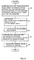
- the graph of figure 2 illustrates a prior art situation in which a mobile station carries out a handover HO from base station BTS1 to base station BTS2 at the location HO, and in which a mobile station is commanded to use the maximum transmitting power MS_TXPWR_MAX(n) of the base station BTS2 as its initial transmitting power MS_TXPWR(n). This results in a sudden RF power peak before the power control algorithm adjusts the mobile station MS transmitting power to an appropriate level.
- the initial transmitting power MS_TXPWR(n) of the mobile station in the target cell following the handover is, instead of the maximum transmitting power MS_TXPWR_MAX(n) of the target cell, adjusted to a value which is determined by utilizing the measurement which the mobile station MS has carried out prior to the handover concerning the receive levels (field strengths) of the downlink signals of the neighbouring cells, which measurement also provides the receive level of the downlink signal of the target cell for the handover.
- cellular networks are usually designed in such a way that there exists a power balance between the downlink and uplink directions, it can be assumed that the level of the downlink signal of the cell approximates the level of the uplink signal at the cell service area.
- a high downlink signal level indicates that the mobile station MS is relatively close to the base station of the cell, and, thus, also a high uplink signal level, if the maximum transmitting power is used.
- the transmitting power level MS_TXPWR(n) of the mobile station MS following the handover can, according to the invention, be optimized by taking into account the level of the downlink signal RX_LEV_NCELL(n) of the target cell which level is measured prior to the handover.
- the cells are assigned an optimum level MsOptLevel for the uplink signal, which level is adequate for the connection, and which the mobile station is to achieve immediately following the handover.
- the optimum level for the uplink signal is advantageously assigned to each cell separately. Because the optimum level of the uplink signal of the cell is adequate for the connection, any measured level for the downlink signal higher than the optimum level for the uplink signal indicates a power margin which can be utilized in order to reduce the transmitting power of the mobile station.
- the maximum transmitting power can be, for example, within the range 13 dBm - 43 dBm.
- RXLEV_NCELL(n) represents the downlink signal level of the target cell (n), which level the mobile station MS measures prior to the handover in measurements concerning the neighbouring cells.
- the level of the downlink signal typically lies in the range -110 dBm ... -47 dBm.
- the function MAX ensures that only positive ( ⁇ 0) differences between the measured level of the downlink signal and the optimum level of the uplink signal are taken into account.
- the graph of figure 3 illustrates a situation of the invention in which situation a mobile station MS carries out a handover HO from the base station BTS1 to the base station BTS2 at the location HO.
- the handover and the power controls are usually carried out by a base station controller BSC whose operation is illustrated by the flow chart of figure 4.
- the mobile station MS As the mobile station MS is in the cell of the current base station BTS1, it carries out measurements in accordance with the handover algorithm employed by the system concerning the level, possibly quality as well, of the downlink signal of the serving cell, and the receive level of the downlink signals of the neighbouring cells.
- the base station BTS1 can measure the level and quality of the uplink signal of the mobile station MS.
- the base station controller searches from its data base the maximum transmitting power MS_TXPWR_MAX(n) of the target cell n, and the optimum level MsOptLevel(n) of the uplink signal.
- the base station controller BSC obtains the receive level RXLEV_NCELL(n) of the downlink signal of the target cell prior to the handover (block 41).
- the base station controller BSC determines an optimum initial power level MS_TXPWR(n) for the mobile station MS in the target cell.
- the measured signal level RXLEV_NCELL(n) is higher than the optimum level MsOptLevel(n) of the uplink signal, in which case the difference in signal levels ⁇ between the measured signal level and the optimum level of the uplink signal can be utilized in order to reduce the transmitting power of the mobile station MS.
- the optimized initial output power MS_TXPWR(n) for the mobile station MS is adjusted (block 43) lower than the maximum transmitting power MS_TXPWR_MAX(n) of the target cell to the extent of the said difference in signal levels ⁇ , as can be seen in figure 3.
- the normal power control algorithm is initiated (block 44). As shown by figure 3, by the present invention unnecessary RF power peaks can be avoided in a handover.
Landscapes
- Engineering & Computer Science (AREA)
- Computer Networks & Wireless Communication (AREA)
- Signal Processing (AREA)
- Mobile Radio Communication Systems (AREA)
- Control Of Eletrric Generators (AREA)
Abstract
Description
- The present invention relates to a power control method and arrangement for a handover in a mobile communication system.
- It is characteristic of a modern mobile communication system that a mobile station is free to roam and connect from one cell to another within the mobile communication system. If a mobile station does not have an ongoing call, the cell crossover only results in registering to a new cell. If a mobile station MS is handling a call during the cell crossover, the call must also be switched to the new cell by a way which causes as little disturbance to the call as possible. The cell crossover process during an ongoing call is called a handover. A handover may also be carried out within the cell from one traffic channel to another. In order for the mobile communication system to be able to detect a need for a handover and to select a suitable target cell for the handover, various kinds of measurements are required in order to determine the connection quality and field strength levels of the neighbouring cells. A handover from the serving cell to a neighbouring cell can occur, for example, (1), as measurement results of the mobile station/base station indicate a low signal level and/or quality in the present serving cell, and a better signal level can be obtained in a neighbouring cell, or (2), as a neighbouring cell enables communication at lower transmitting power levels. The latter may occur in cases a mobile station is in a border area between cells. In radio networks, the aim is to avoid unnecessarily high power levels and thus interference elsewhere in the network.
- The transmitting power of a mobile station is usually controlled from the fixed network by a power control algorithm. The mobile station measures the receive level (field strength) and quality of the downlink signal received from the base station of the serving cell, and the base station of the serving cell, in turn, measures the receive level (field strength) and quality of the uplink signal received from the mobile station. On the basis of these measurement results and the preset power control parameters, the power control algorithm determines an appropriate transmitting power level of which the mobile station is then informed in a power control command. During a call, power control is continuous.
- Mobile communication systems of this kind, however, have a problem regarding the post-handover situation. Following the handover, it takes a while before an adequate number of measurement results can be obtained from the mobile station and the base station of the new cell, and before the power control algorithm is able to make an optimal adjustment to the transmitting power levels of the base station and the mobile station. For this reason, the mobile station is first, following the handover, commanded to use the highest transmitting power allowed to it in the new cell. The highest allowed transmitting power ensures an adequate link quality even to those mobile stations that are located in the cell border area as the handover is carried out. If, however, the mobile station is closer by as the handover is carried out, the highest allowed transmitting power might be unnecessarily high. Although the power control rapidly decreases the transmitting power of the mobile station to an appropriate level, the post-handover radio frequency power peaks may cause uplink disturbances in the radio network. Furthermore, overrated power levels unnecessarily shorten the battery life in the battery-powered mobile station.
- Another type of radio system is disclosed in EP 0 255 628 wherein the handover decision is based on measurements made by base sites on a in-use channel.
- The object of the present invention is a power control method for alleviating the aforementioned problem.
- This is obtained by a power control method according to claim 1.
- The invention further relates to a power control system according to claim 6.
- The basic idea of the present invention is to optimize the transmitting power level which the mobile station is to use in each target cell following the handover so that the transmitting power level of the mobile station is lower if measurements made prior to the handover show that uplink signal conditions in the target cell are good. Prior to the handover, however, the mobile station can only measure the downlink signal level of the target cell, the neighbouring cell at the time, and thus the fixed network does not have any kind of measured advance information on the uplink signal conditions in the target cell. The present invention, however, utilizes the fact that cellular networks are designed in such a way that there exists a power balance between the downlink and uplink directions. Thus, it can be assumed that the level of the cell downlink signal approximates the level of the uplink signal at the cell service area. So, a high uplink signal level denotes a high downlink signal level. As the mobile stations measure the broadcast control channel of the neighbouring cells on which the maximum transmitting power is used, it can be assumed that the high level of the downlink signal of the target cell which is measured prior to the handover means that the appropriate transmitting power level of the mobile station following the handover would be lower than the maximum transmitting power level which the mobile station is allowed to use in the target cell. Thus, the transmitting power level which the mobile station is to use following the handover can, according to the invention, be optimized by taking into account the level of the downlink signal of the target cell, which level is measured prior to the handover.
- In the preferred embodiment of the present invention, the target cell is in addition assigned an optimum level for the uplink signal which the mobile station is to achieve immediately following the handover. Because the optimum level of the uplink signal is adequate as far as the connection is concerned, a measured downlink signal level higher than that means a power margin that can be utilized to reduce the transmitting power of the mobile station. According to the invention, following the handover a transmitting power level lower than the maximum transmitting power is used, which lower transmitting power is determined by subtracting the difference between the measured level of the downlink signal of the target cell and the optimum level of the uplink signal of the target cell from the highest transmitting power level of the target cell. The method considerably reduces the transmitting power level of the mobile station in cases the measured downlink level of the target cell is much higher than the optimum level of the uplink signal, in other words, in cases the mobile station is close to the base station of the target cell.
- In the following, the invention will be described in closer detail by illustrating embodiments with reference to the accompanying drawings in which
- figure 1 illustrates a part of a mobile communication system to which the invention can be applied,
- figure 2 is a chart illustrating the prior art transmitting power control,
- figure 3 is a chart and figure 4 a flow chart which illustrate the transmitting power control according to the invention.
-
- The present invention can be applied to any cellular or trunked mobile communication system, such as the Pan-European mobile communication system GSM, DCS1800 (Digital Communication System), PCN (Personal Communication Network), UMC (Universal Mobile Communication), UMTS (Universal Mobile Telecommunication System), FPLMTS (Future Public Land Mobile Telecommunication System), etc.
- Figure 1 illustrates, as an example, a mobile communication system of the GSM type. The GSM (Global System for Mobile Communications) is a Pan-European mobile communication system which is becoming the universal standard. Figure 1 very briefly illustrates the basic elements of the GSM system without going any further into the system. For a closer description of the GSM system, the GSM recommendations and "The GSM System for Mobile Communications", M. Mouly & M. Pautet, Palaiseau, France, 1992, ISBN:2-9507190-0-7 are referred to.
- The GSM system is a cellular radio system. A mobile services switching centre MSC handles the connecting of incoming and outgoing calls. It carries out functions similar to those of an exchange of a public switched telephone network (PSTN). In addition to these, it also carries out functions characteristic of mobile communications only, such as subscriber location management in co-operation with the subscriber registers of the network. As subscriber registers, the GSM system at least includes the home location register HLR and the visitor location register VLR which are not shown in Figure 1. More accurate information of the location of the subscriber, usually the accuracy of the location area, is stored in the visitor location register, there being typically one VLR for each mobile services switching centre MSC, while the HLR knows which VLR area the mobile station MS is visiting. The mobile stations MS are connected to the centre MSC by base station systems. The base station system consists of a base station controller BSC and base stations BTS, i.e. fixed transceivers the mobile stations MS use to communicate with the fixed network over a radio link. One base station controller is used to control several base stations BTS. The tasks of the BSC include, among other things, handovers in cases in which the handover is carried out within the base station, or between two base stations controlled by the same BSC. Figure 1 only shows, for reasons of clarity, a base station system in which nine base stations BTS1-BTS9 are connected to a base station controller BSC, the radio coverage area of which base stations forms the corresponding radio cells C1-C9.
- Decisions on handovers during on-going calls are made by a base station controller BSC on the basis of various handover parameters assigned to each cell, and on the basis of measurement results reported by a mobile station MS and base stations BTS. A handover is normally carried out on the basis of criteria of the radio path, but it can be performed due to other reasons as well, for example, load sharing.
- In accordance with the GSM technical recommendations, for example, a mobile station MS monitors (measures) the level and quality of the downlink signal of the serving cell, and the level of the downlink signal of the neighbouring cells of the serving cell. The base station BTS monitors (measures) the level and quality of the uplink signal received from each mobile station MS served by said base station BTS. All the measurement results are transmitted to the base station controller. Alternatively, all decisions on a handover can be made at a mobile services switching centre MSC to which all the measurement results are in such a case transmitted. A MSC also controls at least those handovers occurring from the area of one base station controller to the area of another.
- If a mobile station MS roams in a radio network, a handover from the traffic channel of the serving cell to the traffic channel of the neighbouring cell is normally performed either (1) as the averaged measurement results of the mobile station MS and/or the base station BTS indicate a low signal level and/or quality from the current serving cell and a better signal level can be obtained from a neighbouring cell, and/or (2) as a neighbouring cell enables communication at lower transmitting power levels, in other words, as the mobile station MS is in a border area between cells. In radio networks, the aim is to avoid unnecessarily high power levels and thus interference elsewhere in the network.
- The base station controller BSC selects according to the system handover algorithm and on the basis of the reported measurement results, one cell from among the neighbouring cells as the target cell for the handover. The selection may be simplest implemented by selecting a neighbouring cell which has the best radio path qualities, i.e. the highest signal level.
- It should be noted that the exact implementation of a handover is not essential to the present invention. The power control of the invention can be introduced into practically all network controlled handover procedures. Thus, it is not necessary to describe a handover in any greater detail in this application.
- The transmitting power of a mobile station is usually controlled from a fixed network by a special power control algorithm. The mobile station measures the receive level (field strength) and quality of the downlink signal received from the base station of the serving cell, and the base station of the serving cell, in turn, measures the receive level (field strength) and quality of the uplink signal received from the mobile station. On the basis of these measurement results and the preset power control parameters, the power control algorithm determines an appropriate transmitting power level of which the mobile station is then informed in a power control command. During a call, power control is continuous.
- It should be noted that the exact implementation of a normal power control is not essential to the present invention, either. The power control of the invention can be introduced into practically all power control algorithms. Thus, it is not necessary to describe the normal power control in any greater detail herein.
- The graph of figure 2 illustrates a prior art situation in which a mobile station carries out a handover HO from base station BTS1 to base station BTS2 at the location HO, and in which a mobile station is commanded to use the maximum transmitting power MS_TXPWR_MAX(n) of the base station BTS2 as its initial transmitting power MS_TXPWR(n). This results in a sudden RF power peak before the power control algorithm adjusts the mobile station MS transmitting power to an appropriate level.
- According to the present invention, the initial transmitting power MS_TXPWR(n) of the mobile station in the target cell following the handover is, instead of the maximum transmitting power MS_TXPWR_MAX(n) of the target cell, adjusted to a value which is determined by utilizing the measurement which the mobile station MS has carried out prior to the handover concerning the receive levels (field strengths) of the downlink signals of the neighbouring cells, which measurement also provides the receive level of the downlink signal of the target cell for the handover. As cellular networks are usually designed in such a way that there exists a power balance between the downlink and uplink directions, it can be assumed that the level of the downlink signal of the cell approximates the level of the uplink signal at the cell service area. So, a high downlink signal level indicates that the mobile station MS is relatively close to the base station of the cell, and, thus, also a high uplink signal level, if the maximum transmitting power is used. So, the transmitting power level MS_TXPWR(n) of the mobile station MS following the handover can, according to the invention, be optimized by taking into account the level of the downlink signal RX_LEV_NCELL(n) of the target cell which level is measured prior to the handover.
- In the preferred embodiment of the invention, the cells are assigned an optimum level MsOptLevel for the uplink signal, which level is adequate for the connection, and which the mobile station is to achieve immediately following the handover. The optimum level for the uplink signal is advantageously assigned to each cell separately. Because the optimum level of the uplink signal of the cell is adequate for the connection, any measured level for the downlink signal higher than the optimum level for the uplink signal indicates a power margin which can be utilized in order to reduce the transmitting power of the mobile station. According to the primary embodiment of the invention, the optimized initial transmitting power MS_TXPWR(n) for the mobile station is calculated in the following way:
- The graph of figure 3 illustrates a situation of the invention in which situation a mobile station MS carries out a handover HO from the base station BTS1 to the base station BTS2 at the location HO. The handover and the power controls are usually carried out by a base station controller BSC whose operation is illustrated by the flow chart of figure 4. As the mobile station MS is in the cell of the current base station BTS1, it carries out measurements in accordance with the handover algorithm employed by the system concerning the level, possibly quality as well, of the downlink signal of the serving cell, and the receive level of the downlink signals of the neighbouring cells. In addition, the base station BTS1 can measure the level and quality of the uplink signal of the mobile station MS. On the basis of these measurements, a decision on a handover is made according to the criteria of the handover algorithm, and the target cell for the handover is selected, in this case the cell of the base station BTS2 (block 40). Following this, the base station controller searches from its data base the maximum transmitting power MS_TXPWR_MAX(n) of the target cell n, and the optimum level MsOptLevel(n) of the uplink signal. In addition, on the basis of measurements the mobile station MS has carried out concerning the neighbouring cells, the base station controller BSC obtains the receive level RXLEV_NCELL(n) of the downlink signal of the target cell prior to the handover (block 41). Then, according to the equation above (block 42), the base station controller BSC determines an optimum initial power level MS_TXPWR(n) for the mobile station MS in the target cell. As can be seen in figure 3, the measured signal level RXLEV_NCELL(n) is higher than the optimum level MsOptLevel(n) of the uplink signal, in which case the difference in signal levels Δ between the measured signal level and the optimum level of the uplink signal can be utilized in order to reduce the transmitting power of the mobile station MS. As the handover HO is carried out, the optimized initial output power MS_TXPWR(n) for the mobile station MS is adjusted (block 43) lower than the maximum transmitting power MS_TXPWR_MAX(n) of the target cell to the extent of the said difference in signal levels Δ, as can be seen in figure 3. Following this, the normal power control algorithm is initiated (block 44). As shown by figure 3, by the present invention unnecessary RF power peaks can be avoided in a handover.
- The drawings and their description are only meant to illustrate the present invention. The method and arrangement of the invention is defined in the attached claims.
Claims (7)
- A power control method for a handover in a mobile communication system, characterized by
assigning each cell (C1-C9) a maximum transmitting level at which mobile stations (MS) are allowed to transmit in the cell,
measuring (40) the receive level of a handover target cell at a mobile station (MS) prior to the handover,
determining (42) the transmitting power level of the mobile station (MS) for the target cell by utilizing the measured receive level of the downlink signal of the target cell,
commanding (43) the mobile station (MS) to use said determined transmitting power level as the initial output power level in the target cell following the handover. - A method as claimed in claim 1, characterized in that
each cell (C1-C9) is assigned an optimum level for the uplink signal which the mobile station (MS) is to achieve following the handover,
the transmitting power level which the mobile station (MS) it is to use in the target cell following the handover is set to a value which is lower than the maximum transmitting power level of the target cell by an amount equal to the difference between the optimum level of the uplink signal of the target cell and the measured receive level of the downlink signal, if the measured receive level of the target cell is higher than the optimum level of the uplink signal of the target cell. - A method as claimed in claim 2, characterized by
determining the level difference between the measured receive level of the downlink signal of the target cell and the optimum level of the uplink signal of the target cell,
determining the transmitting power which the mobile station (MS) is to use in the target cell by subtracting said level difference from the maximum transmitting power level of the target cell,
commanding the mobile station (MS) to use said determined transmitting power as the initial power output level in the target cell following the handover. - A method as claimed in claim 1, 2 or 3, characterized in that the mobile station (MS) and the base station (BTS1-BTS9) are prior to the handover informed of the transmitting power level which the mobile station (MS) is to use in the target cell.
- A method as claimed in claim 1, 2 or 3, characterized in that the transmitting power level the mobile station (MS) is to use in the target cell is transmitted to the mobile station (MS) in a handover command, and to the base station (BTS1-BTS9) as the new channel is allocated.
- A power control system for a handover in a mobile communication system, characterized in that each cell (C1-C9) is assigned a maximum transmitting power level (MS_TXPWR_MAX(n)) at which the mobile stations (MS) are allowed to transmit in the cell, and an optimum level for the uplink signal (MsOptLevel(n)) which the mobile station is to achieve following the handover, and that the transmitting power level (MS_TXPWR(n)) of the mobile station (MS) following the handover is lower than the maximum transmitting power level of a target cell by an amount equal to the difference between the optimum level of the uplink signal of the target cell and the receive level of the downlink signal (RXLEV_NCELL(n)) of the target cell as measured prior to the handover, if the measured receive level of the target cell is higher than the optimum level of the uplink signal of the target cell.
- A system as claimed in claim 6, characterized in that the information on the maximum transmitting power levels of the cells (C1-C9) and the optimum levels of the uplink signals is stored in a base station controller (BSC), and that the base station controller comprises means for controlling handover and power in the cells (C1-C9) it serves.
Applications Claiming Priority (3)
| Application Number | Priority Date | Filing Date | Title |
|---|---|---|---|
| FI942805A FI111580B (en) | 1994-06-13 | 1994-06-13 | A power control method and arrangement for a handover in a mobile communication system |
| FI942805 | 1994-06-13 | ||
| PCT/FI1995/000340 WO1995035003A1 (en) | 1994-06-13 | 1995-06-12 | Power control method and arrangement for handover in a mobile communication system |
Publications (2)
| Publication Number | Publication Date |
|---|---|
| EP0806120A1 EP0806120A1 (en) | 1997-11-12 |
| EP0806120B1 true EP0806120B1 (en) | 2005-05-11 |
Family
ID=8540907
Family Applications (1)
| Application Number | Title | Priority Date | Filing Date |
|---|---|---|---|
| EP95922536A Expired - Lifetime EP0806120B1 (en) | 1994-06-13 | 1995-06-12 | Power control method and arrangement for handover in a mobile communication system |
Country Status (9)
| Country | Link |
|---|---|
| US (1) | US5862489A (en) |
| EP (1) | EP0806120B1 (en) |
| JP (1) | JP3871707B2 (en) |
| CN (1) | CN1092461C (en) |
| AT (1) | ATE295667T1 (en) |
| AU (1) | AU695283B2 (en) |
| DE (1) | DE69534205T2 (en) |
| FI (1) | FI111580B (en) |
| WO (1) | WO1995035003A1 (en) |
Cited By (1)
| Publication number | Priority date | Publication date | Assignee | Title |
|---|---|---|---|---|
| US8908635B2 (en) | 2007-05-23 | 2014-12-09 | Telefonaktiebolaget L M Ericsson (Publ) | Method and a network node for controlling output uplink and downlink power levels in a mobile communications system |
Families Citing this family (37)
| Publication number | Priority date | Publication date | Assignee | Title |
|---|---|---|---|---|
| ZA965340B (en) * | 1995-06-30 | 1997-01-27 | Interdigital Tech Corp | Code division multiple access (cdma) communication system |
| KR980007105A (en) * | 1996-06-28 | 1998-03-30 | 김광호 | Method for controlling transmission power of mobile station |
| JP4124499B2 (en) * | 1996-11-14 | 2008-07-23 | 富士通株式会社 | Method for performing soft handoff in mobile communication system, mobile communication system and radio base station therefor |
| CA2283859C (en) * | 1997-02-24 | 2005-08-02 | At&T Wireless Services, Inc. | Highly bandwidth-efficient communications |
| US5940743A (en) * | 1997-06-05 | 1999-08-17 | Nokia Mobile Phones Limited | Power control of mobile station transmissions during handoff in a cellular system |
| DE69817950T2 (en) * | 1997-08-12 | 2004-05-13 | Nec Corp. | Mobile station and method for transmitting power control and interference reduction in radio communication systems |
| GB2328584B (en) * | 1997-08-22 | 2002-05-29 | Nokia Mobile Phones Ltd | Switching control method and apparatus for wireless telecommunications |
| US5974327A (en) * | 1997-10-21 | 1999-10-26 | At&T Corp. | Adaptive frequency channel assignment based on battery power level in wireless access protocols |
| US6708041B1 (en) * | 1997-12-15 | 2004-03-16 | Telefonaktiebolaget Lm (Publ) | Base station transmit power control in a CDMA cellular telephone system |
| US6078813A (en) * | 1997-12-16 | 2000-06-20 | Telefonaktiebolaget L M Ericsson (Publ) | Handover quality control in a mobile communications system |
| ID28077A (en) * | 1998-05-07 | 2001-05-03 | Qualcomm Inc | METHODS AND APPARATUS FOR COORDINATING SHORT MESSAGE MESSAGING WITH SEARCH FOR HANDOFFS THAT ARE HAPPY IN A COMMUNICATION WITHOUT WIRE |
| US6434386B1 (en) * | 1998-12-31 | 2002-08-13 | Telefonaktiebolaget L M Ericsson (Publ) | Method and system for monitoring power output in transceivers |
| US6654608B1 (en) | 1999-04-27 | 2003-11-25 | Telefonaktiebolaget Lm Ericsson (Publ) | Tailored power levels at handoff and call setup |
| GB9919595D0 (en) * | 1999-08-18 | 1999-10-20 | Nokia Telecommunications Oy | Connection control in a communication system |
| US6487420B1 (en) | 1999-10-15 | 2002-11-26 | Telefonaktiebolaget Lm Ericsson (Publ) | Adaptive rach power determination for mobile telecommunications user equipment unit |
| FI109163B (en) * | 2000-02-24 | 2002-05-31 | Nokia Corp | Method and apparatus for supporting mobility in a telecommunication system |
| US6937583B1 (en) * | 2001-02-13 | 2005-08-30 | Via Telecom Co., Ltd. | Method and apparatus for controlling forward link power during an intergenerational soft handoff in a CDMA communication system |
| US7003310B1 (en) * | 2001-09-28 | 2006-02-21 | Arraycomm Llc. | Coupled uplink/downlink power control and spatial processing with adaptive antenna arrays |
| SE523400C2 (en) * | 2001-11-30 | 2004-04-13 | Ericsson Telefon Ab L M | Cellular radio communication system utilizing wireless optical links and method of operating the system |
| US20050047369A1 (en) * | 2003-08-25 | 2005-03-03 | Pecen Mark E. | Method and apparatus for mobility impact mitigation in a packet data communication system |
| CN100391301C (en) * | 2004-08-05 | 2008-05-28 | 华为技术有限公司 | A Method of Determining Initial Access Power of Mobile Station after Handover |
| US7430420B2 (en) * | 2004-12-23 | 2008-09-30 | Lucent Technologies Inc. | Cell selection and inter-frequency handover |
| IL170925A (en) * | 2005-09-18 | 2010-12-30 | Alvarion Ltd | Method and device for transmission power control in wireless communications networks |
| KR101253167B1 (en) * | 2006-08-16 | 2013-04-10 | 엘지전자 주식회사 | Method of controlling Mobile Station uplink output power in mobile communication system |
| EP2272280B1 (en) * | 2008-04-03 | 2021-07-14 | Telefonaktiebolaget LM Ericsson (publ) | Method and arrangement for handling handover related parameters in a mobile communications network |
| US8902874B2 (en) | 2008-10-20 | 2014-12-02 | Nokia Siemens Networks Oy | Sounding channel apparatus and method |
| US8358624B1 (en) * | 2008-11-13 | 2013-01-22 | Clearwire Ip Holdings Llc | Bidirectional uplink/downlink handoff |
| US8605644B2 (en) * | 2009-02-12 | 2013-12-10 | Nokia Siemens Networks Oy | Transmission power control for sounding signal for wireless networks |
| CN102165802B (en) * | 2009-06-30 | 2013-06-05 | 华为技术有限公司 | Method and apparatus of communication |
| US9699701B2 (en) * | 2012-08-10 | 2017-07-04 | Qualcomm Incorporated | Mobility operation in LTE |
| US9204356B2 (en) * | 2012-09-04 | 2015-12-01 | Apple Inc. | Reducing call drops in uplink power limited scenarios |
| US9253702B2 (en) | 2012-09-06 | 2016-02-02 | Telefonaktiebolaget L M Ericsson (Publ) | Handover in heterogeneous radio communication networks based on systematic imbalance differences |
| TWI562658B (en) * | 2012-10-10 | 2016-12-11 | Apple Inc | Triggering cell transition in an uplink power limited condition |
| US8867397B2 (en) | 2012-10-17 | 2014-10-21 | Motorola Solutions, Inc. | Method and apparatus for uplink power control in an orthogonal frequency division multiple access communication system |
| US9420512B2 (en) * | 2013-01-17 | 2016-08-16 | Apple Inc. | Handling uplink power limited scenarios |
| AU2016270352B2 (en) | 2015-06-03 | 2020-10-29 | Smule, Inc. | Automated generation of coordinated audiovisual work based on content captured from geographically distributed performers |
| US20220173944A1 (en) * | 2019-03-29 | 2022-06-02 | Sony Group Corporation | Communication control apparatus, communication apparatus, and communication control method |
Citations (1)
| Publication number | Priority date | Publication date | Assignee | Title |
|---|---|---|---|---|
| EP0255628A2 (en) * | 1986-08-01 | 1988-02-10 | Motorola Ltd | Handoff apparatus and method with interference reduction for a radio system |
Family Cites Families (17)
| Publication number | Priority date | Publication date | Assignee | Title |
|---|---|---|---|---|
| US4797947A (en) * | 1987-05-01 | 1989-01-10 | Motorola, Inc. | Microcellular communications system using macrodiversity |
| JPH02215238A (en) * | 1989-02-15 | 1990-08-28 | Matsushita Electric Ind Co Ltd | mobile radio equipment |
| US5042082A (en) * | 1989-06-26 | 1991-08-20 | Telefonaktiebolaget L. M. Ericsson | Mobile assisted handoff |
| SE467332B (en) * | 1990-06-21 | 1992-06-29 | Ericsson Telefon Ab L M | PROCEDURE FOR POWER CONTROL IN A DIGITAL MOBILE PHONE SYSTEM |
| SE466426B (en) * | 1990-07-06 | 1992-02-10 | Ericsson Telefon Ab L M | PROCEDURES FOR HANDOFFS IN A MOBILE RADIO SYSTEM |
| US5276906A (en) * | 1990-09-27 | 1994-01-04 | Motorola, Inc. | Radiotelephone system incorporating two thresholds for handoff |
| US5507018A (en) * | 1991-03-06 | 1996-04-09 | Nokia Telecommunications Oy | Method and a device for controlling a radio transmitter |
| SE9200915D0 (en) * | 1992-03-24 | 1992-03-24 | Ericsson Telefon Ab L M | METHODS IN A CELLULAR MOBILE RADIO COMMUNINCATION SYSTEM |
| GB2271245B (en) * | 1992-09-30 | 1996-05-08 | Roke Manor Research | Improvements in or relating to mobile radio systems |
| DE4304095B4 (en) * | 1993-02-11 | 2005-08-25 | Philips Intellectual Property & Standards Gmbh | mobile system |
| JP2616244B2 (en) * | 1993-05-18 | 1997-06-04 | 日本電気株式会社 | Channel allocation method for mobile communication system |
| FI933209A7 (en) * | 1993-07-14 | 1995-01-15 | Nokia Telecommunications Oy | Method for adjusting transmission power in a cellular radio system and subscriber terminal |
| JP3192839B2 (en) * | 1993-09-20 | 2001-07-30 | 富士通株式会社 | How to determine initial transmit power |
| JP2911090B2 (en) * | 1993-09-29 | 1999-06-23 | エヌ・ティ・ティ移動通信網株式会社 | Mobile communication base station device and mobile station device |
| US5491837A (en) * | 1994-03-07 | 1996-02-13 | Ericsson Inc. | Method and system for channel allocation using power control and mobile-assisted handover measurements |
| US5634195A (en) * | 1995-03-27 | 1997-05-27 | Telefonaktiebolaget Lm Ericsson | System and method for setting of output power parameters in a cellular mobile telecommunication system |
| US5524009A (en) * | 1995-06-07 | 1996-06-04 | Nokia Mobile Phones Ltd. | Fast AGC setting using RSS (I) measurement procedure |
-
1994
- 1994-06-13 FI FI942805A patent/FI111580B/en active
-
1995
- 1995-06-12 WO PCT/FI1995/000340 patent/WO1995035003A1/en not_active Ceased
- 1995-06-12 DE DE69534205T patent/DE69534205T2/en not_active Expired - Lifetime
- 1995-06-12 AT AT95922536T patent/ATE295667T1/en not_active IP Right Cessation
- 1995-06-12 JP JP50169096A patent/JP3871707B2/en not_active Expired - Fee Related
- 1995-06-12 EP EP95922536A patent/EP0806120B1/en not_active Expired - Lifetime
- 1995-06-12 AU AU27390/95A patent/AU695283B2/en not_active Ceased
- 1995-06-12 US US08/765,265 patent/US5862489A/en not_active Expired - Lifetime
- 1995-06-12 CN CN95193557A patent/CN1092461C/en not_active Expired - Fee Related
Patent Citations (1)
| Publication number | Priority date | Publication date | Assignee | Title |
|---|---|---|---|---|
| EP0255628A2 (en) * | 1986-08-01 | 1988-02-10 | Motorola Ltd | Handoff apparatus and method with interference reduction for a radio system |
Cited By (1)
| Publication number | Priority date | Publication date | Assignee | Title |
|---|---|---|---|---|
| US8908635B2 (en) | 2007-05-23 | 2014-12-09 | Telefonaktiebolaget L M Ericsson (Publ) | Method and a network node for controlling output uplink and downlink power levels in a mobile communications system |
Also Published As
| Publication number | Publication date |
|---|---|
| CN1150512A (en) | 1997-05-21 |
| AU695283B2 (en) | 1998-08-13 |
| HK1004183A1 (en) | 1998-11-20 |
| CN1092461C (en) | 2002-10-09 |
| FI942805A0 (en) | 1994-06-13 |
| FI942805L (en) | 1995-12-14 |
| DE69534205D1 (en) | 2005-06-16 |
| DE69534205T2 (en) | 2006-05-04 |
| WO1995035003A1 (en) | 1995-12-21 |
| FI111580B (en) | 2003-08-15 |
| EP0806120A1 (en) | 1997-11-12 |
| JPH10501391A (en) | 1998-02-03 |
| AU2739095A (en) | 1996-01-05 |
| US5862489A (en) | 1999-01-19 |
| JP3871707B2 (en) | 2007-01-24 |
| ATE295667T1 (en) | 2005-05-15 |
Similar Documents
| Publication | Publication Date | Title |
|---|---|---|
| EP0806120B1 (en) | Power control method and arrangement for handover in a mobile communication system | |
| EP0765588B1 (en) | Traffic control method in a hierarchical mobile communication system | |
| US5487174A (en) | Methods in a cellular mobile radio communication system | |
| US6041235A (en) | Handover method and arrangement for a mobile communication system | |
| JP4794362B2 (en) | Trigger mobile station hand-down and hand-off between border cells in cellular radio communication systems | |
| US7054635B1 (en) | Cellular communications network and method for dynamically changing the size of a cell due to speech quality | |
| EP0765587B1 (en) | Handover in a mobile communication system | |
| US6885866B1 (en) | Handover-method in a cellular radio system with two frequency bands | |
| AU5039199A (en) | Handover-method in a cellular radio system | |
| HK1004183B (en) | Power control method and arrangement for handover in a mobile communication system | |
| HK1014097B (en) | A method of bidirectional communication in a cellular mobile radio communication system wherein different base stations are used for the downlink and uplink connection |
Legal Events
| Date | Code | Title | Description |
|---|---|---|---|
| PUAI | Public reference made under article 153(3) epc to a published international application that has entered the european phase |
Free format text: ORIGINAL CODE: 0009012 |
|
| 17P | Request for examination filed |
Effective date: 19961012 |
|
| AK | Designated contracting states |
Kind code of ref document: A1 Designated state(s): AT BE CH DE GB IT LI NL SE |
|
| RAP1 | Party data changed (applicant data changed or rights of an application transferred) |
Owner name: NOKIA NETWORKS OY |
|
| RAP1 | Party data changed (applicant data changed or rights of an application transferred) |
Owner name: NOKIA CORPORATION |
|
| 17Q | First examination report despatched |
Effective date: 20030220 |
|
| GRAP | Despatch of communication of intention to grant a patent |
Free format text: ORIGINAL CODE: EPIDOSNIGR1 |
|
| GRAS | Grant fee paid |
Free format text: ORIGINAL CODE: EPIDOSNIGR3 |
|
| GRAA | (expected) grant |
Free format text: ORIGINAL CODE: 0009210 |
|
| AK | Designated contracting states |
Kind code of ref document: B1 Designated state(s): AT BE CH DE GB IT LI NL SE |
|
| REG | Reference to a national code |
Ref country code: GB Ref legal event code: FG4D |
|
| REG | Reference to a national code |
Ref country code: CH Ref legal event code: EP |
|
| REF | Corresponds to: |
Ref document number: 69534205 Country of ref document: DE Date of ref document: 20050616 Kind code of ref document: P |
|
| PG25 | Lapsed in a contracting state [announced via postgrant information from national office to epo] |
Ref country code: SE Free format text: LAPSE BECAUSE OF FAILURE TO SUBMIT A TRANSLATION OF THE DESCRIPTION OR TO PAY THE FEE WITHIN THE PRESCRIBED TIME-LIMIT Effective date: 20050811 |
|
| REG | Reference to a national code |
Ref country code: CH Ref legal event code: NV Representative=s name: ICB INGENIEURS CONSEILS EN BREVETS SA |
|
| REG | Reference to a national code |
Ref country code: HK Ref legal event code: GR Ref document number: 1004183 Country of ref document: HK |
|
| PLBE | No opposition filed within time limit |
Free format text: ORIGINAL CODE: 0009261 |
|
| STAA | Information on the status of an ep patent application or granted ep patent |
Free format text: STATUS: NO OPPOSITION FILED WITHIN TIME LIMIT |
|
| 26N | No opposition filed |
Effective date: 20060214 |
|
| REG | Reference to a national code |
Ref country code: CH Ref legal event code: PUE Owner name: QUALCOMM INCORPORATED Free format text: NOKIA CORPORATION#KEILALAHDENTIE 4#02150 ESPOO (FI) -TRANSFER TO- QUALCOMM INCORPORATED#5775 MOREHOUSE DRIVE#SAN DIEGO, CA 92121 (US) |
|
| REG | Reference to a national code |
Ref country code: GB Ref legal event code: 732E Free format text: REGISTERED BETWEEN 20090226 AND 20090304 |
|
| NLS | Nl: assignments of ep-patents |
Owner name: QUALCOMM INCORPORATED Effective date: 20090427 |
|
| PGFP | Annual fee paid to national office [announced via postgrant information from national office to epo] |
Ref country code: IT Payment date: 20100621 Year of fee payment: 16 Ref country code: AT Payment date: 20100507 Year of fee payment: 16 |
|
| PGFP | Annual fee paid to national office [announced via postgrant information from national office to epo] |
Ref country code: NL Payment date: 20100607 Year of fee payment: 16 Ref country code: CH Payment date: 20100430 Year of fee payment: 16 Ref country code: BE Payment date: 20100630 Year of fee payment: 16 |
|
| PGFP | Annual fee paid to national office [announced via postgrant information from national office to epo] |
Ref country code: GB Payment date: 20100401 Year of fee payment: 16 Ref country code: DE Payment date: 20100630 Year of fee payment: 16 |
|
| BERE | Be: lapsed |
Owner name: QUALCOMM INC. Effective date: 20110630 |
|
| REG | Reference to a national code |
Ref country code: NL Ref legal event code: V1 Effective date: 20120101 |
|
| REG | Reference to a national code |
Ref country code: CH Ref legal event code: PL |
|
| GBPC | Gb: european patent ceased through non-payment of renewal fee |
Effective date: 20110612 |
|
| PG25 | Lapsed in a contracting state [announced via postgrant information from national office to epo] |
Ref country code: IT Free format text: LAPSE BECAUSE OF NON-PAYMENT OF DUE FEES Effective date: 20110612 Ref country code: AT Free format text: LAPSE BECAUSE OF NON-PAYMENT OF DUE FEES Effective date: 20110612 |
|
| REG | Reference to a national code |
Ref country code: AT Ref legal event code: MM01 Ref document number: 295667 Country of ref document: AT Kind code of ref document: T Effective date: 20110612 |
|
| PG25 | Lapsed in a contracting state [announced via postgrant information from national office to epo] |
Ref country code: BE Free format text: LAPSE BECAUSE OF NON-PAYMENT OF DUE FEES Effective date: 20110630 |
|
| REG | Reference to a national code |
Ref country code: DE Ref legal event code: R119 Ref document number: 69534205 Country of ref document: DE Effective date: 20120103 |
|
| PG25 | Lapsed in a contracting state [announced via postgrant information from national office to epo] |
Ref country code: CH Free format text: LAPSE BECAUSE OF NON-PAYMENT OF DUE FEES Effective date: 20110630 Ref country code: LI Free format text: LAPSE BECAUSE OF NON-PAYMENT OF DUE FEES Effective date: 20110630 Ref country code: DE Free format text: LAPSE BECAUSE OF NON-PAYMENT OF DUE FEES Effective date: 20120103 |
|
| PG25 | Lapsed in a contracting state [announced via postgrant information from national office to epo] |
Ref country code: NL Free format text: LAPSE BECAUSE OF NON-PAYMENT OF DUE FEES Effective date: 20120101 |
|
| PG25 | Lapsed in a contracting state [announced via postgrant information from national office to epo] |
Ref country code: GB Free format text: LAPSE BECAUSE OF NON-PAYMENT OF DUE FEES Effective date: 20110612 |