EP0805960B1 - Medizinisches thermometer - Google Patents
Medizinisches thermometer Download PDFInfo
- Publication number
- EP0805960B1 EP0805960B1 EP95932458A EP95932458A EP0805960B1 EP 0805960 B1 EP0805960 B1 EP 0805960B1 EP 95932458 A EP95932458 A EP 95932458A EP 95932458 A EP95932458 A EP 95932458A EP 0805960 B1 EP0805960 B1 EP 0805960B1
- Authority
- EP
- European Patent Office
- Prior art keywords
- temperature
- patient
- probe
- estimates
- succession
- Prior art date
- Legal status (The legal status is an assumption and is not a legal conclusion. Google has not performed a legal analysis and makes no representation as to the accuracy of the status listed.)
- Expired - Lifetime
Links
- 239000000523 sample Substances 0.000 claims description 78
- 238000000034 method Methods 0.000 claims description 16
- 238000009529 body temperature measurement Methods 0.000 claims description 15
- 238000005259 measurement Methods 0.000 claims description 6
- 238000005070 sampling Methods 0.000 claims description 5
- 238000010792 warming Methods 0.000 description 11
- 230000008569 process Effects 0.000 description 9
- PXHVJJICTQNCMI-UHFFFAOYSA-N Nickel Chemical compound [Ni] PXHVJJICTQNCMI-UHFFFAOYSA-N 0.000 description 4
- 238000010438 heat treatment Methods 0.000 description 4
- 239000004593 Epoxy Substances 0.000 description 3
- 229910001220 stainless steel Inorganic materials 0.000 description 3
- 239000010935 stainless steel Substances 0.000 description 3
- RYGMFSIKBFXOCR-UHFFFAOYSA-N Copper Chemical compound [Cu] RYGMFSIKBFXOCR-UHFFFAOYSA-N 0.000 description 2
- 230000008901 benefit Effects 0.000 description 2
- 230000001143 conditioned effect Effects 0.000 description 2
- 229910052802 copper Inorganic materials 0.000 description 2
- 239000010949 copper Substances 0.000 description 2
- 229910052759 nickel Inorganic materials 0.000 description 2
- 238000012360 testing method Methods 0.000 description 2
- 230000001225 therapeutic effect Effects 0.000 description 2
- 238000004458 analytical method Methods 0.000 description 1
- 230000008859 change Effects 0.000 description 1
- 238000010276 construction Methods 0.000 description 1
- 230000001934 delay Effects 0.000 description 1
- 230000003292 diminished effect Effects 0.000 description 1
- 239000011521 glass Substances 0.000 description 1
- 230000006872 improvement Effects 0.000 description 1
- 238000003780 insertion Methods 0.000 description 1
- 230000037431 insertion Effects 0.000 description 1
- 239000000463 material Substances 0.000 description 1
- 238000012986 modification Methods 0.000 description 1
- 230000004048 modification Effects 0.000 description 1
- 230000000737 periodic effect Effects 0.000 description 1
- 238000012545 processing Methods 0.000 description 1
- 210000000664 rectum Anatomy 0.000 description 1
- 230000000717 retained effect Effects 0.000 description 1
- 230000035939 shock Effects 0.000 description 1
- 230000001052 transient effect Effects 0.000 description 1
Images


Classifications
-
- G—PHYSICS
- G01—MEASURING; TESTING
- G01K—MEASURING TEMPERATURE; MEASURING QUANTITY OF HEAT; THERMALLY-SENSITIVE ELEMENTS NOT OTHERWISE PROVIDED FOR
- G01K7/00—Measuring temperature based on the use of electric or magnetic elements directly sensitive to heat ; Power supply therefor, e.g. using thermoelectric elements
- G01K7/42—Circuits effecting compensation of thermal inertia; Circuits for predicting the stationary value of a temperature
Definitions
- This invention relates generally to medical thermometers and, more particularly, to electronic thermometers that estimate, or predict, a patient's temperature based on a series of samples of a probe-mounted temperature sensor.
- thermometers of this particular kind have been in common use in the clinical environment for many years.
- the thermometers typically include an elongated probe configured for convenient oral, rectal, or axillary use, with a thermistor mounted within the probe's remote tip.
- a hygienic, plastic probe cover is placed over the probe, and the probe is then applied to its appropriate location on the patient, whereupon the temperature of the probe and thermistor begin to rise toward the patient temperature.
- the thermometer periodically samples the thermistor signal and, using one of several known algorithms, predicts the thermistor's eventual temperature. This temperature prediction is displayed long before the thermistor's temperature actually reaches that predicted temperature.
- thermometers have been used in the past, all of them providing reasonably accurate temperature predictions as quickly as about 30 seconds after the thermometers are applied to the patients. This represents a marked improvement over the time delays encountered using more traditional glass thermometers, which typically are on the order of about 3 minutes.
- the time delay is primarily due to the heat capacity of the probe and the fact that applying the probe to the patient, e.g., beneath the tongue, draws down the temperature of the tissue in the immediate region of the probe.
- thermometers Although prior prediction-type electronic thermometers have proven to be highly successful in the clinical environment, there is still a need to for a further improved thermometer that can provide accurate predictions of a patient's actual temperature in substantially less time than generally was achievable in the past. At the same time, however, the thermometer must not sacrifice accuracy for speed and must be of durable construction able to withstand frequent use on multiple patients. The thermometer also must be substantially insensitive to variations in the particular manner in which the thermometer is applied to the patient. The present invention fulfils these needs.
- thermometer for estimating the temperature of a patient
- the thermometer comprising a probe; a temperature sensor mounted in the probe, for producing a signal indicating the temperature of the probe; a display; a sampler for repeatedly sampling the temperature sensor signal, to produce a succession of temperature measurements; and a processor configured to repeatedly estimate the patient's temperature based on the succession of temperature measurements and to repeatedly determine the stability of the resulting succession of temperature estimates, wherein the processor provides a final estimate of the patient's temperature, for display on the display, when the determined stability of the succession of temperature estimates has a prescribed level of stability, characterised in that the prescribed level of stability is selected in accordance with the values of the succession of temperature estimates.
- the prescribed level of stability used by the processor depends upon a first set of conditions applied to the succession of temperature estimates, used when the most recent estimate of the patient's temperature lies within a predetermined range of values, or on a second set of conditions applied to a succession of temperature estimates, used when the most recent estimate of the patient's temperature lies outside the predetermined range of values.
- Employing the present invention may enable the probe to be applied to the patient, whereby the processor repeatedly samples the temperature sensor signal, e.g., at regular time intervals, and estimates the patient's temperature based on a plurality of successive samples.
- the processor terminates its estimating and conditions a display to display the most recent temperature estimate when a prescribed level of stability has been met, that prescribed level of stability varying in accordance with the values of the successive temperatures estimates.
- the processor terminates its processing and conditions the display to display the processor's determination of the patient's temperature, which is the most recent temperature estimate.
- the processor continues to sample the temperature sensor signal and to provide repeated temperature estimates until a second selected number of successive estimates, e.g., six, lie within a second predetermined temperature error range, e.g., a span of 0.14°C (0.25°F).
- a second predetermined temperature error range e.g. 0.14°C (0.25°F).
- a method for estimating a patient's temperature using a medical thermometer of the kind having a probe and a sensor that produces a signal indicating the temperature of the probe comprising the steps of: repeatedly measuring the sensor signal, to produce a succession of temperature measurements; repeatedly evaluating the succession of temperature measurements using predetermined criteria, to provide a succession of estimates of the patient's temperature; and repeatedly determining the stability of the succession of temperature estimates; characterised by the step of displaying a final estimate of patient's temperature when the determined stability of the succession of temperature estimates has been determined to have a prescribed level of stability, wherein the prescribed level of stability is selected according to the values of the successive temperature estimates.
- thermometer 11 configured to accurately estimate a patient's temperature.
- the thermometer includes a base housing 13 and an elongated probe 15 connected together by a flexible wire 16.
- the probe can be stored conveniently in a well 17 formed in the base housing.
- a hygienic probe cover (not shown) selected from a probe cover supply 18 is placed over the probe, and the probe is applied to a patient, e.g., orally or rectally.
- the probe includes a thermistor 19 within its remote tip, and electrical circuitry in the base housing 13 monitors the thermistor and estimates the patient's temperature in substantially less time than previously was required by thermometers of this kind.
- the final temperature estimate is displayed on a display 20 mounted on the base housing.
- the elongated probe 15 includes an elongated base 21 and a hollow probe tip 23 configured for secure attachment to the base.
- the tip is formed of stainless steel having a substantially uniform thickness of about 0.1 millimeters, and it includes a cylindrical section 25 that secures to the base and a frusto-conical section 27 at its remote end.
- the thermistor 19 is bonded to the inside wall of the frusto-conical section using a thermally-conductive epoxy 28, such as Stycast #2850.
- Stainless steel has relatively poor thermal conductivity; however, its high strength allows the probe tip 23 to be made very thin so that heat can be conducted from the patient to the thermistor 19 relatively quickly.
- the thinness of the wall, coupled with the material's relatively poor heat conductivity, also provides the advantage of reducing the wicking of heat axially along the probe tip, whereby heat flow to the thermistor is further enhanced.
- the open end of the cylindrical section 25 of the probe tip 23 is sized to slide over and be retained by the remote end of the probe's base 21.
- the tip and base can advantageously be secured together using Ecco Bond #51 epoxy.
- the base likewise is formed of stainless steel and is tubular, but with a wall thickness of preferably about 0.4 millimeters.
- Electrical leads 29 connect the thermistor 19 with the electrical circuitry located in the base housing 13. These leads extend through the tubular openings in the probe tip 23 and probe base 21.
- short sections of the leads at the site of the thermistor are formed of nickel, which has relatively poor heat conductivity.
- the remaining sections of the leads are formed of copper.
- the nickel and copper lead sections are secured to each other by connectors 30.
- the thermometer 11 further is configured to preliminarily warm the probe tip to a temperature of about 33.89°C (93oF) prior to its insertion. This is accomplished using a resistor 31 bonded to the inside wall of the frusto-conical section 27 of the hollow probe's tip 23.
- the resistor is bonded using a thermally conductive epoxy 33, such as Stycast #2850, at a circumferential location diametrically opposed to that of the thermistor.
- this warming is effected only upon removal of the probe from its storage well 17 in the base housing 13. Electrical current is applied to the resistor via leads 35.
- a substantially continuous pulse of electrical current is initially applied to the resistor 31, for a controllably selected time duration, typically on the order of 1 to 2 seconds.
- the specific time duration is selected according to the amount of warming determined to be required, which of course depends upon the probe tip's initial temperature at the time it is withdrawn from the well 17.
- the thermometer 11 therefore is configured to measure this initial temperature and to determine the difference between that measured temperature and the desired 33.89°C (93oF) target temperature.
- the initial temperature preferably is measured using the thermistor 19. Alternatively, it could be measured using a separate thermistor mounted within the base housing 13, preferably adjacent to the probe cover supply 18.
- the appropriate duration for the initial warming pulse is selected by normalizing the desired temperature rise to the probe's known temperature rise undergone when a pulse of a prescribed fixed duration is applied, as determined in a prior test conducted when this same probe 15 was first attached to the base housing 13.
- a pulse duration of precisely 200 milliseconds will increase the probe tip's temperature from 22.78°C to 25.00°C (73.0oF to 77.0oF) a span of 2.22°C (4.0oF)
- a pulse duration of about 900 milliseconds will be required to increase the probe's temperature to 33.89°C (93oF) from an initial start temperature measured to be 23.89°C (75oF).
- the electrical power delivered to the resistor 31 during the initial warming pulse can vary according to the voltage level of the battery (not shown) located within the base housing 13. If that voltage is relatively low, for example, then a proportionately longer pulse duration will be required to provide the desired heating.
- the thermometer 11 therefore is configured to measure the battery voltage while a warming pulse is being applied and to adjust the pulse duration, accordingly, to provide the desired warming.
- the warming function of the resistor 31 could alternatively be provided by the thermistor 19, itself. In that case, care must be taken to ensure that the thermistor temperature is measured only after the transient effects of any warming pulse applied to it have adequately diminished.
- the thermometer 11 preferably includes a fail-safe circuit (not shown) that monitors the electrical signal applied to the resistor 31 and intervenes to terminate the signal if it is detected to be present continuously.
- the initial pulse signal applied to the resistor is periodically interrupted for brief durations, e.g., one millisecond, thus making it only substantially continuous, as mentioned above. This periodic interruption ensures that the fail-safe circuit does not mistake the pulse signal for a failure and intervene to terminate the signal.
- thermometer 11 After the probe tip 23 has been warmed to approximately the 33.89°C (93oF) target temperature after removal of the probe 15 from the well 17 of the base housing 13, the thermometer 11 operates in a sustain mode, in which it endeavors to regulate the probe tip's temperature at the desired 33.89°C (93oF) value.
- a microprocessor (not shown) that is part of the electrical circuitry to periodically read the thermistor 19, e.g., every 200 milliseconds, to ascertain its current temperature, and to provide pulse-width modulated pulses to the resistor 31.
- K 1 , K 1 ', K 2 , K 2 ' and K 3 all are derived empirically, based on the particular probe structure being used.
- the third term in the equation can be limited to a predetermined maximum value. Those skilled in the art are readily capable of deriving an appropriate equation.
- This pulse-width modulation control scheme is effective in maintaining the probe tip's temperature at the desired 33.89°C (93oF) even when the probe 15 receives the thermal shock of having a hygienic probe cover placed over it.
- the probe tip's temperature can be reduced substantially, which causes the temp error and temp slope terms in the above equation to increase substantially. This results in pulses of increased width being applied to the resistor 31, to rapidly bring the probe temperature back to the desired 33.89°C (93oF) value.
- the probe 15 is placed into the patient's mouth typically at least 5 seconds after the probe has been removed from the well 17 of the base housing 13. At that time, the temperature of the probe tip 23 and the surrounding probe cover should be at or near the 33.89°C (93°F) target temperature. That is only slightly below the expected mouth temperature, so that very little draw down of the temperature of the patient's mouth tissue will occur. This is important in minimizing the time delay to the accurate estimation of the patient's temperature.
- the microprocessor When the probe tip is placed into the patient's mouth, its temperature should almost immediately rise above the 33.89°C (93oF) target value, which should cause the thermometer 11 immediately to reduce to zero duration the pulses it had been applying to the resistor 31. Thereafter, the microprocessor continues to sample the thermistor 19 every 200 milliseconds and, after alternate samples (thus, every 400 milliseconds), analyzes the successive temperature samples and endeavors to curve-fit those samples to the curve for a typical patient. Numerous prediction algorithms are known and are suitable for this purpose, although a least mean square error curve fit is preferred. The curve for the typical patient is previously derived based on tests performed on a large number of individuals.
- the microprocessor terminates its sampling of the thermistor 19 and estimating of the patient's temperature only when a prescribed number of successive temperature estimates, which are made every 400 milliseconds, are sufficiently close to each other to provide at least a limited measure of confidence that the estimate is indeed correct.
- a therapeutic intervention could be indicated, so it is important to exercise greater care in ensuring that the temperature estimate is indeed correct.
- the display 20 is conditioned to provide a display of only the final temperature estimate, and it remains blank while the successive estimates are being computed.
- the display could be conditioned to provide a display of all of the successive temperature estimates, and some means of alerting the operator, e.g., a beeper, could be provided when the estimating function has been completed.
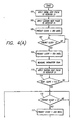
- FIGS. 4(A) and 4(B) depict a simplified flowchart of the operational steps performed by the microprocessor in controllably heating the probe tip 23 after its removal from the well 17 of the base housing 13 and, thereafter, in sampling the thermistor signal and estimating the patient's temperature.
- the processor applies an initial heating pulse to the resistor 31.
- this step entails measuring the thermistor's initial temperature upon removal of the probe 15 from the well, as well as measuring the voltage on the battery located within the base housing.
- the pulse duration is controllably adjusted according to these two measurements.
- the processor applies a second, sustain pulse to the resistor, which has a duration calculated to sustain the thermistor's temperature at about 33.89°C (93.0oF) when it is repeated every 200 milliseconds.
- a decrementing predict clock is set to 200 milliseconds, to initiate the warming pulse cycle. Thereafter, the program remains in step 107 until the predict clock has timed out. The predict clock then is reset to 200 milliseconds in step 109, and the thermistor signal is measured in step 111.
- Another sustain pulse of the same duration as the first sustain pulse is applied to the resistor 31 in step 113, and it is then determined in step 114 whether or not the change in the thermistor's temperature since the previous measurement is less than 0.11°C (0.2oF). Such a condition would indicate that the thermistor's temperature has generally stabilized at some temperature at or near 33.89°C (93oF). In this initial pass through step 114, only one thermistor measurement is available, so the condition automatically is not met, and the program therefore returns to step 107, where it remains until the predict clock has timed out.
- the program then repeats this open-loop sustain pulse cycle by proceeding again through steps 109, 111, 113 and 114, until it finally is determined in step 114 that the thermistor's temperature has adequately stabilized.
- the program proceeds to step 115, where it waits for the predict clock to time out, and in turn to step 117, where it again sets the predict clock to 200 milliseconds.
- the thermistor signal is again measured in step 119, and it is determined in step 121 whether or not 1) the current temperature measurement exceeds 34.72°C (94.5oF) or 2) the current temperature measurement exceeds 33.06°C (91.5oF) and, at the same time, a pulse width of zero duration is computed using the formula set forth above.
- step 139 the program proceeds to step 139, where it computes the temp error, temp slope, and integrated temp error variables, and calculates the appropriate pulse width using the formula set forth above. This calculated pulse width then is applied to the resistor 31, in step 141, and the program returns to step 115, where it waits for the predict clock to time out. The program then proceeds again through the steps 117, 119, and 121.
- step 121 Eventually, one of the two conditions set forth in step 121 will be met, which ordinarily will occur only after the thermometer probe 15 has been placed into the patient's mouth.
- the program proceeds to step 123, where it determines whether or not an even number of settings of the predict clock have been made. This is required because patient temperature estimates are produced only after alternate readings of the thermistor 19. If not, meaning that an odd number of such settings have been made, then the program returns to step 115, as described above.
- step 123 When it is determined at step 123 that an even number of predict clock settings have been made, the program proceeds to step 125, where it implements a prescribed prediction algorithm to estimate the patient's temperature based on the accumulated temperature samples. Thereafter, in step 127, it is determined whether or not the time since starting the prediction process has exceeded 1.2 seconds. If it has not, the program returns to step 115, where it remains until the predict clock has decremented to zero. Thus, seven thermistor samples and four temperature estimates must be made before 1.2 seconds have elapsed.
- step 127 If, on the other hand, it is determined at step 127 that the time period since starting the prediction process has in fact exceeded 1.2 seconds, then the program proceeds to step 129 where it is determined whether or not the current temperature estimate lies within a relatively normal range of 36.11°C to 37.50°C (97oF to 99.5oF). If it does, then the program proceeds to step 131, where it is determined whether or not the difference between the maximum and minimum temperature estimates during the preceding 1.2 seconds (i.e., seven 200 millisecond samples) is less than 0.11°C (0.2oF). If it is, then it is determined that the current temperature estimate is valid, and the program proceeds to step 133 of displaying that temperature estimate.
- step 129 it is determined whether or not the current temperature estimate lies within a relatively normal range of 36.11°C to 37.50°C (97oF to 99.5oF). If it does, then the program proceeds to step 131, where it is determined whether or not the difference between the maximum and minimum temperature estimates during the preceding 1.2 seconds
- step 129 determines whether or not the current temperature estimate lies outside the 36.11°C to 37.50°C (97oF to 99.5oF) range, or if it is determined at step 131 that the difference between the maximum and minimum temperature estimates exceeds 0.11°C (0.2oF), then the program proceeds to step 135, where it is determined whether or not the time since starting the prediction process has exceeded 3.6 seconds. If it has not, the program returns to step 115, as described above. Thus, for patient temperatures outside the relatively normal range of 36.11°C to 37.50°C (97oF to 99.5oF), the thermistor sampling and temperature estimating will continue for at least 3.6 seconds.
- step 137 it is determined whether or not the difference between the maximum and minimum temperature estimates during the preceding 2.0 seconds (i.e., eleven 200-millisecond samples) is less than 0.14°C (0.25oF). If it is, then it is determined that the current temperature estimate is valid and the program proceeds to step 133 of displaying the current temperature estimate. On the other hand, it is determined in step 137 that the difference between the maximum and minimum temperature estimates during the preceding 2.0 seconds exceeds 0.14°C (0.25oF) then the program returns to step 115 and the prediction process continues. Only when it is finally determined at step 137 that the maximum and minimum temperature estimates differ by less than 0.14°C (0.25°F) will the prediction process finally be concluded.
- step 121 where it is determined whether or not the current temperature measurement remains above 34.72°C (94.5oF) or alternatively remains above 33.06°C (91.5oF) with no warming pulses being applied to the resistor 31, if it is determined ever that that condition is no longer being met, then it is deduced that the probe 15 has been removed from the patient's mouth and that the warming procedure described above must be resumed.
- step 139 the program calculates an appropriate pulse duration for the pulse-width modulation signal, using the formula set forth above. Then, in step 141, the pulse is applied to the resistor 31. The program then returns to the step 115 of waiting for the predict clock to decrement to zero.
- thermometer 11 determines that a temperature estimate outside the 36.11°C to 37.50°C (97oF to 99.5oF) range is indeed valid when the end of the 3.6 second time period is first reached. More than 3.6 seconds ordinarily is required only when the probe 15 is not properly seated within the patient's mouth or rectum, or otherwise is being moved about excessively.
Landscapes
- Physics & Mathematics (AREA)
- General Physics & Mathematics (AREA)
- Measuring And Recording Apparatus For Diagnosis (AREA)
- Measuring Temperature Or Quantity Of Heat (AREA)
Claims (12)
- Medizinisches Thermometer zum Einschätzen der Temperatur eines Patienten, enthaltend:eine Sonde (15);einen in der Sonde (15) angebrachten Temperatursensor zum Erzeugen eines Signals, das die Temperatur der Sonde (15) anzeigt;eine Anzeige (20);einen Abtaster zum wiederholten Abtasten des Temperatursensorsignals, um eine Abfolge von Temperaturmessungen zu erzeugen; undeinen Prozessor, der so konfiguriert ist, dass er die Temperatur des Patienten basierend auf der Abfolge von Temperaturmessungen wiederholt einschätzt und wiederholt die Stabilität der resultierenden Abfolge von Temperatureinschätzungen bestimmt. wobei der Prozessor eine endgültige Einschätzung der Temperatur des Patienten zur Anzeige auf der Anzeige (20) abgibt, wenn die bestimmte Stabilität der Abfolge von Temperaturmessungen ein vorgeschriebenes Stabilitätsniveau hat, dadurch gekennzeichnet, dass das vorgeschriebene Stabilitätsniveau in Übereinstimmung mit den Werten der Abfolge von Temperatureinschätzungen ausgewählt wird.
- Medizinisches Thermometer nach Anspruch 1, dadurch gekennzeichnet, dass das von dem Prozessor verwendete vorgeschriebene Stabilitätsniveau von einem ersten Satz von Bedingungen abhängig ist, der auf die Abfolge von Temperatureinschätzungen angewandt wird, welcher verwendet wird, wenn die jüngste Einschätzung der Temperatur des Patienten innerhalb eines vorbestimmten Wertebereichs liegt, oder von einem zweiten Satz von Bedingungen, der auf die Abfolge von Temperatureinschätzungen angewandt wird, welcher verwendet wird, wenn die jüngste Einschätzung der Temperatur des Patienten außerhalb des vorbestimmten Wertebereichs liegt.
- Medizinisches Thermometer nach Anspruch 2, dadurch gekennzeichnet, dassder erste, von dem Prozessor verwendete Satz von Bedingungen eine Bedingung enthält, dass eine erste vorbestimmte Anzahl von aufeinanderfolgenden Temperatureinschätzungen innerhalb eines ersten vorbestimmten Bereichs von Temperaturwerten liegt; undder zweite, von dem Prozessor verwendete Satz von Bedingungen eine Bedingung enthält, dass eine zweite vorbestimmte Anzahl von aufeinanderfolgenden Temperatureinschätzungen, die größer als die erste vorbestimmte Anzahl ist, innerhalb eines zweiten vorbestimmten Bereichs von Temperaturwerten liegt.
- Medizinisches Thermometer nach Anspruch 3, dadurch gekennzeichnet, dassder erste Satz von Bedingungen ferner eine Bedingung enthält, dass der Abtaster das Temperatursensorsignal über mindestens eine erste vorbestimmte Mindestzeitdauer abgetastet hat; undder zweite Satz von Bedingungen ferner eine Bedingung enthält, dass der Abtaster das Temperatursensorsignal über mindestens eine zweite vorbestimmte Mindestzeitdauer abgetastet hat, die länger als die erste vorbestimmte Mindestzeitdauer ist.
- Medizinisches Thermometer nach Anspruch 3 oder nach Anspruch 4, dadurch gekennzeichnet, dass der erste vorbestimmte Bereich von Temperaturwerten kleiner ist als der zweite vorbestimmte Bereich von Temperaturwerten.
- Medizinisches Thermometer nach einem der vorstehenden Ansprüche, gekennzeichnet durcheine an der Sonde (20) in einer vorbestimmten Beziehung zu dem Temperatursensor (19) angebrachte elektrische Heizung (31); unddadurch, dass der Prozessor so konfiguriert ist, dass er eine Ausgangstemperatur an einem Startzeitpunkt misst, bevor der Patient die Sonde aufnimmt, und an die Heizung ein elektrisches Anfangssignal anlegt, das einen vorgeschriebenen Parameter hat, der gemäß der Ausgangstemperaturmessung zum Startzeitpunkt variiert, um die Sonde zu erwärmen.
- Medizinisches Thermometer nach Anspruch 6, dadurch gekennzeichnet, dassdie Ausgangstemperaturmessung zum Startzeitpunkt eine Messung der Sondentemperatur ist; undder Prozessor die Ausgangstemperaturmessung zum Startzeitpunkt durch Messen des Temperatursensorsignals erzeugt.
- Medizinisches Thermometer nach Anspruch 1, dadurch gekennzeichnet, dass der Abtaster das Temperatursensorsignal in regelmäßigen Zeitintervallen abtastet.
- Medizinisches Thermometer nach einem der vorstehenden Ansprüche, dadurch gekennzeichnet, dass die Anzeige keine Einschätzung der Temperatur des Patienten anzeigt, bevor der Prozessor nicht bestimmt hat, dass das vorgeschriebene Stabilitätsniveau erreicht ist.
- Verfahren zum Einschätzen der Temperatur eines Patienten unter Verwendung eines medizinischen Thermometers der Bauart, die eine Sonde (20) und einen Sensor (19) hat, der ein Signal erzeugt, das die Temperatur der Sonde anzeigt, welches Verfahren die Schritte enthält:wiederholtes Messen des Sensorsignals, um eine Abfolge von Temperaturmessungen zu erzeugen;wiederholtes Bewerten der Abfolge von Temperaturmessungen unter Verwendung von vorbestimmten Kriterien, um eine Abfolge von Einschätzungen der Temperatur des Patienten abzugeben; undwiederholtes Bestimmen der Stabilität der Abfolge von Temperatureinschätzungen:
gekennzeichnet durch den Schritt des Anzeigens einer endgültigen Einschätzung der Temperatur des Patienten, wenn festgestellt wird, dass die bestimmte Stabilität der Abfolge der Temperatureinschätzungen ein vorgeschriebenes Stabilitätsniveau hat, wobei das vorgeschriebene Stabilitätsniveau gemäß den Werten der aufeinanderfolgenden Temperatureinschätzungen ausgewählt wird. - Verfahren nach Anspruch 10, dadurch gekennzeichnet, dass das vorgeschriebene Stabilitätsniveau, das bei der Anzeige verwendet wird, einen ersten Satz von Bedingungen enthält, der verwendet wird, wenn die jüngste Einschätzung der Temperatur des Patienten innerhalb eines vorbestimmten Wertebereichs liegt, und einen zweiten Satz von Bedingungen, der verwendet wird, wenn die jüngste Einschätzung der Temperatur des Patienten außerhalb des vorbestimmten Wertebereichs liegt.
- Verfahren nach Anspruch 11, dadurch gekennzeichnet, dassder erste Satz von Bedingungen, der bei der Anzeige verwendet wird, eine Bedingung enthält, dass wiederholtes Messen und wiederholtes Bewerten über eine erste vorbestimmte Mindestzeitdauer durchgeführt werden, und ferner eine Bedingung enthält, dass eine erste vorbestimmte Anzahl von aufeinanderfolgenden Temperatureinschätzungen innerhalb eines ersten vorbestimmten Bereichs von Temperaturwerten liegt; undder zweite Satz von Bedingungen, der bei der Anzeige verwendet wird, eine Bedingung enthält, dass wiederholtes Messen und wiederholtes Bewerten über eine zweite vorbestimmte Mindestzeitdauer durchgeführt werden, die länger als die erste vorbestimmte Zeitdauer ist, und ferner eine Bedingung enthält, dass eine zweite vorbestimmte Anzahl von aufeinanderfolgenden Temperatureinschätzungen innerhalb eines zweiten vorbestimmten Wertebereichs liegt.
Applications Claiming Priority (5)
| Application Number | Priority Date | Filing Date | Title |
|---|---|---|---|
| US303344 | 1989-01-30 | ||
| US30334494A | 1994-09-09 | 1994-09-09 | |
| US333958 | 1994-11-03 | ||
| US08/333,958 US5632555A (en) | 1994-09-09 | 1994-11-03 | Medical thermometer |
| PCT/US1995/011450 WO1996007877A1 (en) | 1994-09-09 | 1995-09-11 | Medical thermometer |
Publications (3)
| Publication Number | Publication Date |
|---|---|
| EP0805960A1 EP0805960A1 (de) | 1997-11-12 |
| EP0805960A4 EP0805960A4 (de) | 1997-11-26 |
| EP0805960B1 true EP0805960B1 (de) | 2003-05-02 |
Family
ID=26973414
Family Applications (1)
| Application Number | Title | Priority Date | Filing Date |
|---|---|---|---|
| EP95932458A Expired - Lifetime EP0805960B1 (de) | 1994-09-09 | 1995-09-11 | Medizinisches thermometer |
Country Status (5)
| Country | Link |
|---|---|
| US (3) | US5632555A (de) |
| EP (1) | EP0805960B1 (de) |
| CA (1) | CA2199511C (de) |
| DE (1) | DE69530610T2 (de) |
| WO (1) | WO1996007877A1 (de) |
Families Citing this family (83)
| Publication number | Priority date | Publication date | Assignee | Title |
|---|---|---|---|---|
| US5738441A (en) * | 1995-07-11 | 1998-04-14 | The United States Of America As Represented By The Administrator Of The National Aeronautics And Space Administration | Electronic clinical predictive thermometer using logarithm for temperature prediction |
| USD402212S (en) | 1997-11-12 | 1998-12-08 | Headwaters Research & Development, Inc. | RF thermometer receiver |
| USD402213S (en) | 1997-11-12 | 1998-12-08 | Headwaters Research & Development, Inc. | RF thermometer transmitter |
| IL126224A0 (en) * | 1998-09-15 | 1999-05-09 | Gerlitz Jonathan | Ear thermometer and detector therefor |
| US6109784A (en) * | 1998-10-05 | 2000-08-29 | Micro Weiss Electronics | Fast response digital thermometer |
| JP2000111414A (ja) | 1998-10-09 | 2000-04-21 | Hyakuryaku Kigyo Kofun Yugenkoshi | 医療体温計 |
| US6349269B1 (en) * | 1998-12-11 | 2002-02-19 | Dell U.S.A., L.P. | Thermal management data prediction system |
| US6355916B1 (en) * | 1999-05-18 | 2002-03-12 | Alaris Medical Systems, Inc. | Closed loop system and method for heating a probe |
| US6270252B1 (en) | 1999-05-18 | 2001-08-07 | Alaris Medical Systems, Inc. | Predictive temperature measurement system |
| US6332867B1 (en) | 1999-06-09 | 2001-12-25 | Vsm Technology Inc. | Method and apparatus for measuring values of physiological parameters |
| US6250802B1 (en) * | 1999-10-12 | 2001-06-26 | Homecare Technologies Ltd | Electronic thermometer with preheating |
| US6773405B2 (en) * | 2000-09-15 | 2004-08-10 | Jacob Fraden | Ear temperature monitor and method of temperature measurement |
| US7014358B2 (en) * | 2001-02-19 | 2006-03-21 | Braun Gmbh | Radiation thermometer comprising a heated measuring tip |
| US6631287B2 (en) | 2001-04-03 | 2003-10-07 | Welch Allyn, Inc. | Infrared thermometer |
| EP1249691A1 (de) * | 2001-04-11 | 2002-10-16 | Omron Corporation | Elektronisches Fieberthermometer |
| US6839651B2 (en) | 2001-06-27 | 2005-01-04 | Sherwood Services Ag | Probe tip thermal isolation and fast prediction algorithm |
| US6632016B2 (en) * | 2001-07-06 | 2003-10-14 | Min-Ying Chen | Method of stabilizing an infrared clinical thermometer and the apparatus thereof |
| US20040071190A1 (en) * | 2002-10-11 | 2004-04-15 | Hsiao-Yi Chang | Temperature probe and thermometer having the same |
| US20050063454A1 (en) * | 2002-01-18 | 2005-03-24 | Chu-Yih Yu | Thermometer having a disposable temperature probe |
| US6850789B2 (en) * | 2002-07-29 | 2005-02-01 | Welch Allyn, Inc. | Combination SPO2/temperature measuring apparatus |
| DE10257926B8 (de) * | 2002-10-07 | 2007-10-11 | Actherm Inc., Chu Pei | Elektronisches klinisches Thermometer mit schnellem Ansprechverhalten |
| US6827488B2 (en) | 2002-10-10 | 2004-12-07 | Welch Allyn, Inc. | Sealed probe chamber for thermometry apparatus |
| US6971790B2 (en) * | 2002-10-11 | 2005-12-06 | Welch Allyn, Inc. | Thermometry probe calibration method |
| US20040071182A1 (en) * | 2002-10-11 | 2004-04-15 | Welch Allyn, Inc. | Thermometry probe calibration method |
| US6979121B2 (en) * | 2002-10-18 | 2005-12-27 | Mesure Technology, Co., Ltd. | Temperature probe and thermometer having the same |
| US20050123022A1 (en) * | 2002-10-18 | 2005-06-09 | Mesure Technology Co., Ltd. | Temperature probe and thermometer having the same |
| EP1419759B1 (de) * | 2002-11-18 | 2012-12-26 | Rohm And Haas Company | Haarformungszusammensetzung mit langandauernder Festigungswirkung und Verfahren zum Haarformen |
| US7213969B2 (en) * | 2002-11-25 | 2007-05-08 | Kaz, Incorporated | Axillary thermometer |
| US7484887B2 (en) * | 2003-02-20 | 2009-02-03 | Ysis Incorporated | Digitally modified resistive output for a temperature sensor |
| US7374336B2 (en) * | 2003-06-16 | 2008-05-20 | Jacob Fraden | Contact thermometer for body cavity |
| US7785266B2 (en) | 2003-08-19 | 2010-08-31 | Advanced Monitors Corporation | Medical thermometer for determining body core temperature |
| US7938783B2 (en) * | 2003-08-19 | 2011-05-10 | Advanced Monitors Corporation | Medical body core thermometer |
| US7021824B2 (en) * | 2003-10-20 | 2006-04-04 | Welch Allyn, Inc. | Switch assembly for thermometry apparatus |
| US20050101843A1 (en) * | 2003-11-06 | 2005-05-12 | Welch Allyn, Inc. | Wireless disposable physiological sensor |
| DE102004001931A1 (de) * | 2004-01-14 | 2005-08-04 | Braun Gmbh | Kontakt-Thermometer zur Bestimmung der Körpertemperatur |
| US7850650B2 (en) | 2005-07-11 | 2010-12-14 | Covidien Ag | Needle safety shield with reset |
| US7828773B2 (en) | 2005-07-11 | 2010-11-09 | Covidien Ag | Safety reset key and needle assembly |
| US7905857B2 (en) | 2005-07-11 | 2011-03-15 | Covidien Ag | Needle assembly including obturator with safety reset |
| US7857507B2 (en) * | 2004-11-16 | 2010-12-28 | Welch Allyn, Inc. | Temperature patch and method of using the same |
| US7815367B2 (en) * | 2004-11-16 | 2010-10-19 | Welch Allyn, Inc. | Multi-site infrared thermometer |
| US7572056B2 (en) * | 2004-11-16 | 2009-08-11 | Welch Allyn, Inc. | Probe cover for thermometry apparatus |
| US7318004B2 (en) * | 2005-04-01 | 2008-01-08 | Cardinal Health 303, Inc. | Temperature prediction system and method |
| USD525886S1 (en) | 2005-06-03 | 2006-08-01 | Kaz, Incorporated | Axillary thermometer |
| US20060276747A1 (en) | 2005-06-06 | 2006-12-07 | Sherwood Services Ag | Needle assembly with removable depth stop |
| US20060276772A1 (en) * | 2005-06-06 | 2006-12-07 | Sherwood Services Ag | Bayonet release of safety shield for needle tip |
| US7731692B2 (en) | 2005-07-11 | 2010-06-08 | Covidien Ag | Device for shielding a sharp tip of a cannula and method of using the same |
| US20070041424A1 (en) * | 2005-08-16 | 2007-02-22 | Mordechai Lev | Axillary thermometer |
| US7422367B2 (en) | 2005-08-29 | 2008-09-09 | Kaz, Incorporated | Baby rectal thermometer |
| US7316507B2 (en) * | 2005-11-03 | 2008-01-08 | Covidien Ag | Electronic thermometer with flex circuit location |
| USD532710S1 (en) | 2005-11-03 | 2006-11-28 | Sherwood Services Ag | Probe handle for thermometer |
| US7654735B2 (en) * | 2005-11-03 | 2010-02-02 | Covidien Ag | Electronic thermometer |
| US20070100253A1 (en) | 2005-11-03 | 2007-05-03 | Sherwood Services Ag | Electronic thermometer with sensor location |
| USD535202S1 (en) | 2005-11-03 | 2007-01-16 | Sherwood Services Ag | Ergonomic electronic thermometer |
| USD544379S1 (en) | 2005-11-10 | 2007-06-12 | Fka Distributing Co. | Underarm thermometer |
| US20070167692A1 (en) * | 2006-01-17 | 2007-07-19 | Kim Brian S | Refrigerator with health monitoring system |
| US7314310B2 (en) * | 2006-04-13 | 2008-01-01 | The General Electric Company | Predictive temperature probe with proximity sensor |
| US7303333B2 (en) * | 2006-04-21 | 2007-12-04 | Mesure Technology Co., Ltd. | Thermometer with soft flexible probe |
| US7507019B2 (en) * | 2006-05-19 | 2009-03-24 | Covidien Ag | Thermometer calibration |
| US20080042075A1 (en) * | 2006-08-21 | 2008-02-21 | Welch Allyn, Inc. | Thermometry apparatus probe sterilization |
| US20080049812A1 (en) * | 2006-08-22 | 2008-02-28 | Mesure Technology Co., Ltd. | Thermometer with Dual Thermal Sensor |
| US7484884B2 (en) * | 2006-09-28 | 2009-02-03 | Welch Allyn, Inc. | Probe for thermometry apparatus having light passage features to enable safe insertion |
| US7549792B2 (en) | 2006-10-06 | 2009-06-23 | Covidien Ag | Electronic thermometer with selectable modes |
| CN101199414B (zh) * | 2006-12-11 | 2010-12-22 | 深圳迈瑞生物医疗电子股份有限公司 | 一种快速体温测量装置及其温度测量方法 |
| US7911881B2 (en) * | 2007-04-20 | 2011-03-22 | Tsd Integrated Controls, Llc | Method and apparatus for ultrasonic sensing |
| EP1988375A1 (de) * | 2007-05-03 | 2008-11-05 | Renishaw plc | Verfahren und Vorrichtung zur schnellen Temperaturmessung |
| US7749170B2 (en) * | 2007-05-22 | 2010-07-06 | Tyco Healthcare Group Lp | Multiple configurable electronic thermometer |
| US8357104B2 (en) | 2007-11-01 | 2013-01-22 | Coviden Lp | Active stylet safety shield |
| US8496377B2 (en) | 2007-12-31 | 2013-07-30 | Covidien Lp | Thermometer having molded probe component |
| WO2011007294A1 (en) * | 2009-07-14 | 2011-01-20 | Koninklijke Philips Electronics N.V. | Contact detection device for detecting a physical contact between the contact detection device and an object |
| JP2013500475A (ja) * | 2009-07-23 | 2013-01-07 | カズ ヨーロッパ エスエー | 屈曲プローブを有する口腔体温計 |
| US8794829B2 (en) * | 2009-12-31 | 2014-08-05 | Welch Allyn, Inc. | Temperature-measurement probe |
| US8657758B2 (en) | 2010-12-02 | 2014-02-25 | Welch Allyn, Inc. | Devices and methods for temperature determination |
| US9307912B2 (en) | 2012-08-08 | 2016-04-12 | Welch Allyn, Inc. | Temperature measurement system |
| US9746382B2 (en) | 2012-10-16 | 2017-08-29 | Avery Dennison Retail Information Services, Llc | Sensor with controllable thermal contact for temperature monitoring |
| US10060802B1 (en) | 2013-12-02 | 2018-08-28 | Summer Merie Ragosta | Intelligent digital thermometer |
| US9943232B2 (en) | 2014-02-03 | 2018-04-17 | Welch Allyn, Inc. | Thermometry heating and sensing assembly |
| JP6585609B2 (ja) | 2014-02-28 | 2019-10-02 | パウエル マンスフィールド, インコーポレイテッド | Emg活動を感知するためのシステム |
| CN105030211B (zh) * | 2015-07-29 | 2018-12-11 | 东莞市振海电子科技有限公司 | 快速测温仪及其测温控制方法 |
| US9914543B2 (en) * | 2015-12-09 | 2018-03-13 | The Boeing Company | System and method for aircraft ice detection within a zone of non-detection |
| JP6671252B2 (ja) * | 2016-06-21 | 2020-03-25 | パラマウントベッド株式会社 | ベッドサイド端末及びベッドサイド端末システム |
| EP3727142B1 (de) * | 2017-12-21 | 2023-12-13 | Nokia Technologies Oy | Temperaturmessung |
| CN113155319A (zh) * | 2021-05-17 | 2021-07-23 | 深圳亚希诺科技有限公司 | 一种自动提醒测温及快速测量体温装置及方法 |
| USD1073941S1 (en) * | 2022-01-22 | 2025-05-06 | HJY Forward Medical Investment Co., Ltd. | Disposable integrated endoscope |
Family Cites Families (26)
| Publication number | Priority date | Publication date | Assignee | Title |
|---|---|---|---|---|
| US880272A (en) * | 1907-11-11 | 1908-02-25 | William H Bristol | Thermo-electrical system. |
| US3025706A (en) * | 1957-11-20 | 1962-03-20 | Victory Engineering Corp | Temperature sensing device |
| US3258957A (en) * | 1962-01-25 | 1966-07-05 | Parsons C A & Co Ltd | Non-destructive testing of materials |
| US3729998A (en) * | 1970-08-10 | 1973-05-01 | Royal Medical Corp | Electronic, digital thermometer |
| US3832669A (en) * | 1970-08-10 | 1974-08-27 | Royal Medical Corp | Temperature-sensing device |
| US3832902A (en) * | 1970-09-12 | 1974-09-03 | Tokai Rika Co Ltd | Temperature measuring method and device |
| US3791214A (en) * | 1971-08-10 | 1974-02-12 | A Keith | Digital clinical thermometer |
| DE2157029A1 (de) * | 1971-11-17 | 1973-05-24 | Daimler Benz Ag | Sonde zum messen von temperaturen |
| US3738173A (en) * | 1971-11-22 | 1973-06-12 | Ivac Corp | Temperature sensing probe and disposable probe cover |
| US3828332A (en) * | 1972-06-19 | 1974-08-06 | Honeywell Inc | Temperature responsive circuit having a high frequency output signal |
| US3834237A (en) * | 1972-10-05 | 1974-09-10 | Leeds & Northrup Co | Thermocouple for surface temperature measurements |
| DE2358396A1 (de) * | 1972-11-24 | 1974-06-06 | Royston Electronics Pty Ltd | Elektrischer loetkolben |
| FR2305720A1 (fr) * | 1975-03-26 | 1976-10-22 | Gouault Jean | Appareil de releve de temperatures superficielles, notamment cutanees |
| JPS5425882A (en) * | 1977-07-29 | 1979-02-27 | Omron Tateisi Electronics Co | Preheating type electronic clinical thermometer |
| JPS5461584A (en) * | 1977-10-26 | 1979-05-17 | Hitachi Iruma Denshi Kk | Thermistor thermometer |
| SU685965A1 (ru) * | 1977-12-02 | 1979-09-15 | Научно-Исследовательский Институт Строительной Физики Госстроя Ссср | Тепловой зонд |
| US4158965A (en) * | 1978-01-05 | 1979-06-26 | Electromedics, Inc. | Electronic thermometer with heat conditioned probe |
| JPS5853295B2 (ja) * | 1978-02-10 | 1983-11-28 | 株式会社東芝 | 電子式体温計 |
| US4183248A (en) * | 1978-08-08 | 1980-01-15 | Rwb Labs | Fast response electronic thermometer probe |
| GB2084329B (en) * | 1980-09-15 | 1984-07-04 | Diatek Inc | Electronic thermometer |
| US4574359A (en) * | 1982-12-21 | 1986-03-04 | Terumo Kabushiki Kaisha | Electronic clinical thermometer, and method of measuring body temperature |
| US4602642A (en) * | 1984-10-23 | 1986-07-29 | Intelligent Medical Systems, Inc. | Method and apparatus for measuring internal body temperature utilizing infrared emissions |
| JPS62165132A (ja) * | 1986-01-16 | 1987-07-21 | Omron Tateisi Electronics Co | 電子体温計 |
| JPS6340825A (ja) * | 1986-08-07 | 1988-02-22 | Terumo Corp | 電子体温計 |
| US5259389A (en) * | 1990-10-24 | 1993-11-09 | Terumo Kabushiki Kaisha | Electronic clincal thermometer |
| US5392031A (en) * | 1992-03-17 | 1995-02-21 | Terumo Kabushiki Kaisha | Electronic clinical thermometer |
-
1994
- 1994-11-03 US US08/333,958 patent/US5632555A/en not_active Expired - Lifetime
-
1995
- 1995-09-11 DE DE69530610T patent/DE69530610T2/de not_active Expired - Lifetime
- 1995-09-11 CA CA002199511A patent/CA2199511C/en not_active Expired - Fee Related
- 1995-09-11 WO PCT/US1995/011450 patent/WO1996007877A1/en not_active Ceased
- 1995-09-11 EP EP95932458A patent/EP0805960B1/de not_active Expired - Lifetime
-
1997
- 1997-05-20 US US08/859,050 patent/US6000846A/en not_active Expired - Lifetime
-
1999
- 1999-03-26 US US09/277,059 patent/US6036361A/en not_active Expired - Lifetime
Also Published As
| Publication number | Publication date |
|---|---|
| EP0805960A1 (de) | 1997-11-12 |
| WO1996007877A1 (en) | 1996-03-14 |
| CA2199511C (en) | 2004-05-18 |
| EP0805960A4 (de) | 1997-11-26 |
| CA2199511A1 (en) | 1996-03-14 |
| DE69530610D1 (de) | 2003-06-05 |
| US5632555A (en) | 1997-05-27 |
| DE69530610T2 (de) | 2004-03-25 |
| US6036361A (en) | 2000-03-14 |
| US6000846A (en) | 1999-12-14 |
Similar Documents
| Publication | Publication Date | Title |
|---|---|---|
| EP0805960B1 (de) | Medizinisches thermometer | |
| AU2002254423B2 (en) | Probe tip thermal isolation and fast prediction algorithm | |
| AU2002254423A1 (en) | Probe tip thermal isolation and fast prediction algorithm | |
| EP1567842B1 (de) | Thermometriesondenkalibrationsverfahren | |
| JP4927260B2 (ja) | プローブを加熱するための閉ループシステム | |
| EP1864098B1 (de) | Temperaturvorhersagesystem und -verfahren | |
| EP1183508B1 (de) | Prädiktives temperaturmesssystem | |
| US8197132B2 (en) | Electronic thermometer with selectable modes | |
| US4158965A (en) | Electronic thermometer with heat conditioned probe | |
| JP2000111419A (ja) | 高速応答ディジタル温度計 | |
| US20020191675A1 (en) | Electronic clinical thermometer | |
| CA2226506A1 (en) | Electronic clinical thermometer |
Legal Events
| Date | Code | Title | Description |
|---|---|---|---|
| PUAI | Public reference made under article 153(3) epc to a published international application that has entered the european phase |
Free format text: ORIGINAL CODE: 0009012 |
|
| 17P | Request for examination filed |
Effective date: 19970327 |
|
| AK | Designated contracting states |
Kind code of ref document: A1 Designated state(s): DE FR GB NL |
|
| A4 | Supplementary search report drawn up and despatched |
Effective date: 19971008 |
|
| AK | Designated contracting states |
Kind code of ref document: A4 Designated state(s): DE FR GB NL |
|
| 17Q | First examination report despatched |
Effective date: 20010531 |
|
| GRAH | Despatch of communication of intention to grant a patent |
Free format text: ORIGINAL CODE: EPIDOS IGRA |
|
| GRAH | Despatch of communication of intention to grant a patent |
Free format text: ORIGINAL CODE: EPIDOS IGRA |
|
| GRAA | (expected) grant |
Free format text: ORIGINAL CODE: 0009210 |
|
| AK | Designated contracting states |
Designated state(s): DE FR GB NL |
|
| REG | Reference to a national code |
Ref country code: GB Ref legal event code: FG4D |
|
| REF | Corresponds to: |
Ref document number: 69530610 Country of ref document: DE Date of ref document: 20030605 Kind code of ref document: P |
|
| ET | Fr: translation filed | ||
| PLBE | No opposition filed within time limit |
Free format text: ORIGINAL CODE: 0009261 |
|
| STAA | Information on the status of an ep patent application or granted ep patent |
Free format text: STATUS: NO OPPOSITION FILED WITHIN TIME LIMIT |
|
| 26N | No opposition filed |
Effective date: 20040203 |
|
| PG25 | Lapsed in a contracting state [announced via postgrant information from national office to epo] |
Ref country code: FR Free format text: LAPSE BECAUSE OF NON-PAYMENT OF DUE FEES Effective date: 20060531 |
|
| REG | Reference to a national code |
Ref country code: FR Ref legal event code: ST Effective date: 20060531 |
|
| REG | Reference to a national code |
Ref country code: FR Ref legal event code: D3 |
|
| PGFP | Annual fee paid to national office [announced via postgrant information from national office to epo] |
Ref country code: NL Payment date: 20090924 Year of fee payment: 15 |
|
| REG | Reference to a national code |
Ref country code: NL Ref legal event code: V1 Effective date: 20110401 |
|
| PG25 | Lapsed in a contracting state [announced via postgrant information from national office to epo] |
Ref country code: NL Free format text: LAPSE BECAUSE OF NON-PAYMENT OF DUE FEES Effective date: 20110401 |
|
| PGFP | Annual fee paid to national office [announced via postgrant information from national office to epo] |
Ref country code: DE Payment date: 20130927 Year of fee payment: 19 |
|
| PGFP | Annual fee paid to national office [announced via postgrant information from national office to epo] |
Ref country code: FR Payment date: 20130919 Year of fee payment: 19 Ref country code: GB Payment date: 20130927 Year of fee payment: 19 |
|
| REG | Reference to a national code |
Ref country code: DE Ref legal event code: R119 Ref document number: 69530610 Country of ref document: DE |
|
| GBPC | Gb: european patent ceased through non-payment of renewal fee |
Effective date: 20140911 |
|
| REG | Reference to a national code |
Ref country code: FR Ref legal event code: ST Effective date: 20150529 |
|
| PG25 | Lapsed in a contracting state [announced via postgrant information from national office to epo] |
Ref country code: GB Free format text: LAPSE BECAUSE OF NON-PAYMENT OF DUE FEES Effective date: 20140911 Ref country code: DE Free format text: LAPSE BECAUSE OF NON-PAYMENT OF DUE FEES Effective date: 20150401 |
|
| PG25 | Lapsed in a contracting state [announced via postgrant information from national office to epo] |
Ref country code: FR Free format text: LAPSE BECAUSE OF NON-PAYMENT OF DUE FEES Effective date: 20140930 |