EP0805647B1 - Non-invasive medical sensor - Google Patents
Non-invasive medical sensor Download PDFInfo
- Publication number
- EP0805647B1 EP0805647B1 EP96900653A EP96900653A EP0805647B1 EP 0805647 B1 EP0805647 B1 EP 0805647B1 EP 96900653 A EP96900653 A EP 96900653A EP 96900653 A EP96900653 A EP 96900653A EP 0805647 B1 EP0805647 B1 EP 0805647B1
- Authority
- EP
- European Patent Office
- Prior art keywords
- emitter
- radiation
- annular
- photodetectors
- detection means
- Prior art date
- Legal status (The legal status is an assumption and is not a legal conclusion. Google has not performed a legal analysis and makes no representation as to the accuracy of the status listed.)
- Expired - Lifetime
Links
- 230000005855 radiation Effects 0.000 claims abstract description 16
- 239000000126 substance Substances 0.000 claims abstract description 6
- 230000005670 electromagnetic radiation Effects 0.000 claims abstract description 5
- 238000012544 monitoring process Methods 0.000 claims abstract description 3
- 238000001514 detection method Methods 0.000 claims description 12
- 238000005259 measurement Methods 0.000 claims description 8
- 230000001419 dependent effect Effects 0.000 claims description 4
- 230000035945 sensitivity Effects 0.000 claims description 4
- 238000000034 method Methods 0.000 claims description 3
- 210000000056 organ Anatomy 0.000 claims 4
- 230000006335 response to radiation Effects 0.000 claims 2
- 230000008878 coupling Effects 0.000 abstract description 6
- 238000010168 coupling process Methods 0.000 abstract description 6
- 238000005859 coupling reaction Methods 0.000 abstract description 6
- 230000003287 optical effect Effects 0.000 abstract description 5
- 230000003321 amplification Effects 0.000 description 2
- 238000010586 diagram Methods 0.000 description 2
- 238000003199 nucleic acid amplification method Methods 0.000 description 2
- 238000010521 absorption reaction Methods 0.000 description 1
- 238000010304 firing Methods 0.000 description 1
Images


Classifications
-
- A—HUMAN NECESSITIES
- A61—MEDICAL OR VETERINARY SCIENCE; HYGIENE
- A61B—DIAGNOSIS; SURGERY; IDENTIFICATION
- A61B5/00—Measuring for diagnostic purposes; Identification of persons
- A61B5/145—Measuring characteristics of blood in vivo, e.g. gas concentration or pH-value ; Measuring characteristics of body fluids or tissues, e.g. interstitial fluid or cerebral tissue
- A61B5/1455—Measuring characteristics of blood in vivo, e.g. gas concentration or pH-value ; Measuring characteristics of body fluids or tissues, e.g. interstitial fluid or cerebral tissue using optical sensors, e.g. spectral photometrical oximeters
-
- G—PHYSICS
- G01—MEASURING; TESTING
- G01N—INVESTIGATING OR ANALYSING MATERIALS BY DETERMINING THEIR CHEMICAL OR PHYSICAL PROPERTIES
- G01N21/00—Investigating or analysing materials by the use of optical means, i.e. using sub-millimetre waves, infrared, visible or ultraviolet light
- G01N21/17—Systems in which incident light is modified in accordance with the properties of the material investigated
- G01N21/47—Scattering, i.e. diffuse reflection
- G01N21/4795—Scattering, i.e. diffuse reflection spatially resolved investigating of object in scattering medium
Definitions
- the present invention relates to apparatus for the non-invasive quantitative measurement of a substance in a human or animal body, and in particular to apparatus for such measurement utilising electromagnetic radiation.
- the present invention is directed to an improvement of the system described in published international patent application WO 91/17697.
- a sensor generally designated 1
- a sensor consists of a central emitter core 5 carrying light from four sub-emitter laser-diodes each capable of emitting infra-red radiation at a discrete wavelength within the range 700 to 1300nm.
- a primary inner annular photodetector ring 3 Arranged concentrically around the core 5 is a primary inner annular photodetector ring 3 and, spaced therefrom, a secondary outer annular photodetector ring 2.
- the photodetector rings 2, 3 are connected to respective channels 7, 8 of suitable electronic amplification and signal processing circuitry.
- the processed output signals are then passed via signal steering circuitry 9 and an analog to digital converter 12 to a microprocessor control unit 13 programmed to calculate set algorithms dependent on the ratio of the two output signals, thus enabling a quantitative measurement of the amount of a substance in living tissue to be obtained.
- This measurement is then recorded or displayed on a VDU 10 and a chart recorder 11.
- Data can also be stored on a computer 16.
- a laser power supply drive and firing circuitry 14 is provided, and this, together with the signal processing channels, 7, 8, is controlled by a timing sequen' controller 15 connected to the microprocessor control 13.
- This system assumes the overall detection sensitivities of the two channels, i.e. the optical coupling efficiencies between the body and the two detectors and the gains of the two detector channels, to be precisely matched, or at least well defined. If matched, this allows the detection sensitivities between the two channels effectively to cancel each other out. If the detection sensitivities are well defined, this allows the final results to be corrected.
- the signal attenuation measured between the photodetectors 2, 3 should be due to absorption occurring in the measurement region.
- DE-U-9203101.3 describes a surface sensor arrangement for investigating biological and technical structures.
- Various emitter-sensor configurations are described.
- six detectors are arranged on a first circle at the centre of which is disposed a first emitter, with further emitters being arranged on a second circle surrounding the first circle.
- apparatus for the non-invasive monitoring of a substance in living tissue as defined in Claim 1.
- annular or part annular electromagnetic radiation emitter 17 is disposed between annular photodetectors 2 and 3 such that the spacing between the emitter 17 and the detectors 2, 3 is substantially equal.
- the output signals produced by the photodetectors 2, 3 provide a measure of the relative optical coupling and the relative gains of the two detector channels, and this information can be used to correct the output from the photodetectors 2, 3 occurring when the detectors 2, 3 are caused to receive radiation solely from the first emitter 5, e.g. when the first emitter 5 is energised with the second emitter 17 not being energised, such as occurs during an actual measurement process.
- the photodetectors 2, 3 are connected not only to respective channels 7, 8 of suitable electronic amplification and signal processing circuitry, but also to two inputs of processing circuitry 18, which processes the output signals occurring when the photodetectors 2, 3 are caused to receive radiation solely from the second emitter 17.
- This processing circuitry 18 generates an output which is fed to the signal steering circuitry 9 such that the processing of the output signals of the channels 7, 8 is made dependent on the output of the processing circuitry 18, such that the output signals are corrected for any differences in optical coupling or gains of the two detector channels.
Landscapes
- Physics & Mathematics (AREA)
- Health & Medical Sciences (AREA)
- Life Sciences & Earth Sciences (AREA)
- General Health & Medical Sciences (AREA)
- Optics & Photonics (AREA)
- Pathology (AREA)
- Biophysics (AREA)
- Heart & Thoracic Surgery (AREA)
- General Physics & Mathematics (AREA)
- Immunology (AREA)
- Analytical Chemistry (AREA)
- Spectroscopy & Molecular Physics (AREA)
- Chemical & Material Sciences (AREA)
- Engineering & Computer Science (AREA)
- Biomedical Technology (AREA)
- Biochemistry (AREA)
- Medical Informatics (AREA)
- Molecular Biology (AREA)
- Surgery (AREA)
- Animal Behavior & Ethology (AREA)
- Public Health (AREA)
- Veterinary Medicine (AREA)
- Measurement Of The Respiration, Hearing Ability, Form, And Blood Characteristics Of Living Organisms (AREA)
- Investigating Or Analysing Materials By Optical Means (AREA)
Abstract
Description
- The present invention relates to apparatus for the non-invasive quantitative measurement of a substance in a human or animal body, and in particular to apparatus for such measurement utilising electromagnetic radiation.
- The present invention is directed to an improvement of the system described in published international patent application WO 91/17697.
- In that system, there is provided an arrangement as shown in Figures 1, 2 and 3 in which a sensor, generally designated 1, consists of a
central emitter core 5 carrying light from four sub-emitter laser-diodes each capable of emitting infra-red radiation at a discrete wavelength within the range 700 to 1300nm. Arranged concentrically around thecore 5 is a primary innerannular photodetector ring 3 and, spaced therefrom, a secondary outerannular photodetector ring 2. - The
photodetector rings respective channels 7, 8 of suitable electronic amplification and signal processing circuitry. The processed output signals are then passed via signal steering circuitry 9 and an analog todigital converter 12 to amicroprocessor control unit 13 programmed to calculate set algorithms dependent on the ratio of the two output signals, thus enabling a quantitative measurement of the amount of a substance in living tissue to be obtained. This measurement is then recorded or displayed on aVDU 10 and a chart recorder 11. Data can also be stored on acomputer 16. - A laser power supply drive and
firing circuitry 14 is provided, and this, together with the signal processing channels, 7, 8, is controlled by a timing sequen'controller 15 connected to themicroprocessor control 13. - This system assumes the overall detection sensitivities of the two channels, i.e. the optical coupling efficiencies between the body and the two detectors and the gains of the two detector channels, to be precisely matched, or at least well defined. If matched, this allows the detection sensitivities between the two channels effectively to cancel each other out. If the detection sensitivities are well defined, this allows the final results to be corrected.
- Thus, the signal attenuation measured between the
photodetectors - However, over the duration of a measurement, it is quite likely that moisture may build up under the sensors which may alter the coupling efficiencies of the two detectors independently.
- It would therefore be desirable to provide an arrangement which attempts to overcome, or at least mitigate, this problem.
- DE-U-9203101.3 describes a surface sensor arrangement for investigating biological and technical structures. Various emitter-sensor configurations are described. In one arrangement, six detectors are arranged on a first circle at the centre of which is disposed a first emitter, with further emitters being arranged on a second circle surrounding the first circle.
- In accordance with the present invention there is provided apparatus for the non-invasive monitoring of a substance in living tissue as defined in Claim 1.
- A preferred embodiment of the present invention will now be described with reference the accompanying drawings, in which:
- Figure 1 is a schematic plan view of conventional apparatus;
- Figure 2 is a cross-section through the apparatus of Figure 1 in use;
- Figure 3 is a block diagram of a conventional control system for use with the apparatus shown in Figures 1 and 2;
- Figure 4 is a cross-section through the apparatus of a preferred embodiment of the present invention; and
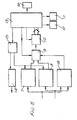
- Figure 5 is a block diagram of a control system for use with the apparatus shown in Figure 4.
-
- Referring to Figure 4, in which the same reference numerals are used as in Figures 1 and 2, an additional annular or part annular electromagnetic radiation emitter 17 is disposed between
annular photodetectors detectors - Thus, when the
photodetectors first emitter 5 not being energised, the output signals produced by thephotodetectors photodetectors detectors first emitter 5, e.g. when thefirst emitter 5 is energised with the second emitter 17 not being energised, such as occurs during an actual measurement process. - With reference to Figure 5, in which the same reference numerals are used as in Figure 3, the
photodetectors respective channels 7, 8 of suitable electronic amplification and signal processing circuitry, but also to two inputs ofprocessing circuitry 18, which processes the output signals occurring when thephotodetectors processing circuitry 18 generates an output which is fed to the signal steering circuitry 9 such that the processing of the output signals of thechannels 7, 8 is made dependent on the output of theprocessing circuitry 18, such that the output signals are corrected for any differences in optical coupling or gains of the two detector channels. - Thus, any unequal gains which are present in the two detector channels, or any inequality in the optical couplings, are thereby compensated.
Claims (5)
- Apparatus for the non-invasive monitoring of a substance in living tissue, the apparatus comprising:characterised in that said apparatus further comprises:a) first emitter means (5) capable of emitting electromagnetic radiation and being arrangeable in use in contact with skin, tissue or organ of a patient;b) first radiation detection means (3) spaced from said first emitter means (5) and arrangeable in use in contact with the skin, tissue or organ of said patient;c) means (8) for producing a first electrical output signal dependent on the intensity of the radiation detected by said first radiation detector means (3);d) second radiation detection means (2) spaced from said first emitter means (5) by a distance greater than said spacing between said first radiation detection means (3) and said first emitter means (5) and arrangeable in use in contact with the skin, tissue or organ of said patient;e) means (7) for producing a second electrical output signal dependent on the intensity of the radiation detected by said second radiation detection means (2); andf) means (9) for processing said first and second output signals generated in response to radiation received from said first emitter means (5);
g) second emitter means (17) capable of emitting electromagnetic radiation and being arrangeable in use in contact with the skin, tissue or organ of said patient, and being spaced from said first (3) and second (2) radiation detection means by substantially the same distance;
said processing means (9) being arranged to process said first and second output signals in dependence on the values of said first and second output signals generated in response to radiation received from said second emitter means (17), thereby to provide a quantitative measurement of the amount of said substance in said living tissue which is compensated against differences in detection sensitivity between said first (3) and second (2) radiation detection means. - Apparatus as claimed in claim 1, wherein at least one of said first (3) and second (2) detection means is at least part annular.
- Apparatus as claimed in claim 1 or claim 2, wherein said first (3) and second (2) detection means comprise annular detectors arranged concentrically around said first emitter means (5).
- Apparatus as claimed in claim 2 or claim 3, wherein said second emitter means (17) is at least part annular.
- Apparatus as claimed in any one of claims 2 to 4, wherein said second emitter means (17) comprises an annular emitter arranged concentrically around said first emitter means (5).
Applications Claiming Priority (3)
| Application Number | Priority Date | Filing Date | Title |
|---|---|---|---|
| GBGB9501663.0A GB9501663D0 (en) | 1995-01-27 | 1995-01-27 | Non-invasive medical sensor |
| GB9501663 | 1995-01-27 | ||
| PCT/GB1996/000140 WO1996022728A1 (en) | 1995-01-27 | 1996-01-24 | Non-invasive medical sensor |
Publications (2)
| Publication Number | Publication Date |
|---|---|
| EP0805647A1 EP0805647A1 (en) | 1997-11-12 |
| EP0805647B1 true EP0805647B1 (en) | 2000-08-30 |
Family
ID=10768710
Family Applications (1)
| Application Number | Title | Priority Date | Filing Date |
|---|---|---|---|
| EP96900653A Expired - Lifetime EP0805647B1 (en) | 1995-01-27 | 1996-01-24 | Non-invasive medical sensor |
Country Status (6)
| Country | Link |
|---|---|
| EP (1) | EP0805647B1 (en) |
| JP (1) | JPH10512778A (en) |
| AU (1) | AU4455596A (en) |
| DE (1) | DE69610074T2 (en) |
| GB (1) | GB9501663D0 (en) |
| WO (1) | WO1996022728A1 (en) |
Families Citing this family (2)
| Publication number | Priority date | Publication date | Assignee | Title |
|---|---|---|---|---|
| GB9517366D0 (en) * | 1995-08-24 | 1995-10-25 | Johnson & Johnson Medical | Method of quantatively determining one or more characteristics of a substance |
| JP2013024746A (en) * | 2011-07-21 | 2013-02-04 | Hitachi High-Technologies Corp | Automatic analyzer |
Family Cites Families (4)
| Publication number | Priority date | Publication date | Assignee | Title |
|---|---|---|---|---|
| JPH06103257B2 (en) * | 1988-12-19 | 1994-12-14 | 大塚電子株式会社 | Method and apparatus for measuring absorption coefficient of substance using light scattering |
| DE69029152T2 (en) * | 1990-02-15 | 1997-03-06 | Hewlett Packard Gmbh | Procedure for the non-invasive measurement of oxygen saturation |
| GB2244128A (en) * | 1990-05-17 | 1991-11-20 | Abbey Biosystems Ltd | Non-invasive medical sensor |
| DE9203101U1 (en) * | 1992-03-09 | 1992-09-24 | N.I.R. Control Medizintechnik Gmbh, 91456 Diespeck | Sensor arrangement, especially for the investigation of biological and technical structures |
-
1995
- 1995-01-27 GB GBGB9501663.0A patent/GB9501663D0/en active Pending
-
1996
- 1996-01-24 JP JP8522718A patent/JPH10512778A/en not_active Ceased
- 1996-01-24 EP EP96900653A patent/EP0805647B1/en not_active Expired - Lifetime
- 1996-01-24 AU AU44555/96A patent/AU4455596A/en not_active Abandoned
- 1996-01-24 WO PCT/GB1996/000140 patent/WO1996022728A1/en not_active Ceased
- 1996-01-24 DE DE69610074T patent/DE69610074T2/en not_active Expired - Fee Related
Also Published As
| Publication number | Publication date |
|---|---|
| EP0805647A1 (en) | 1997-11-12 |
| DE69610074T2 (en) | 2001-04-12 |
| DE69610074D1 (en) | 2000-10-05 |
| JPH10512778A (en) | 1998-12-08 |
| AU4455596A (en) | 1996-08-14 |
| WO1996022728A1 (en) | 1996-08-01 |
| GB9501663D0 (en) | 1995-03-15 |
Similar Documents
| Publication | Publication Date | Title |
|---|---|---|
| US5419321A (en) | Non-invasive medical sensor | |
| JP3928972B2 (en) | Sensor for optical measurement of blood oxygen saturation, measuring method thereof, and measuring apparatus thereof | |
| US20110166442A1 (en) | System for optically detecting position of an indwelling catheter | |
| US6081734A (en) | Monitoring system for the regular intake of a medicament | |
| KR0170040B1 (en) | Methods and apparatus for the determination of glucose in a biological matrix | |
| US7024001B1 (en) | Stethoscope | |
| DE69329854D1 (en) | PATIENT EXAMINATION BY PHOTON HIKING WITH HIGH DIRECTIONALITY | |
| KR20010067120A (en) | Laser diode optical transducer assembly for non-invasive spectrophotometric blood oxygenation monitoring | |
| JP2006520216A5 (en) | ||
| ES2163731T3 (en) | APPARATUS FOR THE NON-INVASIVE DETECTION OF GLUCOSE LEVELS IN BLOOD. | |
| CA2591551A1 (en) | Isolated layer pulse oximetry | |
| GB2228314A (en) | Optical examination apparatus | |
| EP0760476A3 (en) | Method of quantitatively determining one or more characteristics of a substance | |
| JPH10216114A (en) | Degree of oxygen saturation measuring apparatus | |
| EP0528938B1 (en) | Non-invasive medical sensor | |
| JP2005160641A (en) | Pulse wave detector | |
| EP0805647A1 (en) | Non-invasive medical sensor | |
| JP2007020735A (en) | Biological light measurement device | |
| JPS62231625A (en) | Optical CT scanner device | |
| US5908384A (en) | Apparatus for non-invasive measurement within a human or animal body | |
| WO2001012060A3 (en) | Methods for noninvasive analyte sensing | |
| US6833915B2 (en) | Optical diagnosis system for small animal imaging | |
| JPH11169361A (en) | Biological light measurement device | |
| JP2007111461A (en) | Bio-optical measurement apparatus | |
| GB2323440A (en) | Measuring thickness of a layer within a body |
Legal Events
| Date | Code | Title | Description |
|---|---|---|---|
| PUAI | Public reference made under article 153(3) epc to a published international application that has entered the european phase |
Free format text: ORIGINAL CODE: 0009012 |
|
| 17P | Request for examination filed |
Effective date: 19970801 |
|
| AK | Designated contracting states |
Kind code of ref document: A1 Designated state(s): DE FR GB |
|
| AX | Request for extension of the european patent |
Free format text: SI PAYMENT 970801 |
|
| GRAG | Despatch of communication of intention to grant |
Free format text: ORIGINAL CODE: EPIDOS AGRA |
|
| 17Q | First examination report despatched |
Effective date: 19990916 |
|
| GRAG | Despatch of communication of intention to grant |
Free format text: ORIGINAL CODE: EPIDOS AGRA |
|
| GRAH | Despatch of communication of intention to grant a patent |
Free format text: ORIGINAL CODE: EPIDOS IGRA |
|
| GRAG | Despatch of communication of intention to grant |
Free format text: ORIGINAL CODE: EPIDOS AGRA |
|
| GRAH | Despatch of communication of intention to grant a patent |
Free format text: ORIGINAL CODE: EPIDOS IGRA |
|
| GRAG | Despatch of communication of intention to grant |
Free format text: ORIGINAL CODE: EPIDOS AGRA |
|
| GRAH | Despatch of communication of intention to grant a patent |
Free format text: ORIGINAL CODE: EPIDOS IGRA |
|
| GRAH | Despatch of communication of intention to grant a patent |
Free format text: ORIGINAL CODE: EPIDOS IGRA |
|
| RAP1 | Party data changed (applicant data changed or rights of an application transferred) |
Owner name: CRITIKON COMPANY, L.L.C. |
|
| GRAA | (expected) grant |
Free format text: ORIGINAL CODE: 0009210 |
|
| AK | Designated contracting states |
Kind code of ref document: B1 Designated state(s): DE FR GB |
|
| AX | Request for extension of the european patent |
Free format text: SI PAYMENT 19970801 |
|
| REF | Corresponds to: |
Ref document number: 69610074 Country of ref document: DE Date of ref document: 20001005 |
|
| ET | Fr: translation filed | ||
| PGFP | Annual fee paid to national office [announced via postgrant information from national office to epo] |
Ref country code: FR Payment date: 20010102 Year of fee payment: 6 |
|
| PGFP | Annual fee paid to national office [announced via postgrant information from national office to epo] |
Ref country code: DE Payment date: 20010103 Year of fee payment: 6 |
|
| PGFP | Annual fee paid to national office [announced via postgrant information from national office to epo] |
Ref country code: GB Payment date: 20010105 Year of fee payment: 6 |
|
| PLBE | No opposition filed within time limit |
Free format text: ORIGINAL CODE: 0009261 |
|
| STAA | Information on the status of an ep patent application or granted ep patent |
Free format text: STATUS: NO OPPOSITION FILED WITHIN TIME LIMIT |
|
| 26N | No opposition filed | ||
| REG | Reference to a national code |
Ref country code: GB Ref legal event code: IF02 |
|
| PG25 | Lapsed in a contracting state [announced via postgrant information from national office to epo] |
Ref country code: GB Free format text: LAPSE BECAUSE OF NON-PAYMENT OF DUE FEES Effective date: 20020124 |
|
| PG25 | Lapsed in a contracting state [announced via postgrant information from national office to epo] |
Ref country code: DE Free format text: LAPSE BECAUSE OF NON-PAYMENT OF DUE FEES Effective date: 20020801 |
|
| GBPC | Gb: european patent ceased through non-payment of renewal fee |
Effective date: 20020124 |
|
| PG25 | Lapsed in a contracting state [announced via postgrant information from national office to epo] |
Ref country code: FR Free format text: LAPSE BECAUSE OF NON-PAYMENT OF DUE FEES Effective date: 20020930 |
|
| REG | Reference to a national code |
Ref country code: FR Ref legal event code: ST |