EP0805546B1 - Trägerstruktur für eine supraleitende Wicklung - Google Patents
Trägerstruktur für eine supraleitende Wicklung Download PDFInfo
- Publication number
- EP0805546B1 EP0805546B1 EP96303077A EP96303077A EP0805546B1 EP 0805546 B1 EP0805546 B1 EP 0805546B1 EP 96303077 A EP96303077 A EP 96303077A EP 96303077 A EP96303077 A EP 96303077A EP 0805546 B1 EP0805546 B1 EP 0805546B1
- Authority
- EP
- European Patent Office
- Prior art keywords
- vacuum enclosure
- thermal shield
- superconductive coil
- disposed
- superconducting
- Prior art date
- Legal status (The legal status is an assumption and is not a legal conclusion. Google has not performed a legal analysis and makes no representation as to the accuracy of the status listed.)
- Expired - Lifetime
Links
- 239000000725 suspension Substances 0.000 claims description 13
- 238000001816 cooling Methods 0.000 claims description 9
- 239000004593 Epoxy Substances 0.000 description 4
- 238000002595 magnetic resonance imaging Methods 0.000 description 4
- 239000007787 solid Substances 0.000 description 4
- 230000008901 benefit Effects 0.000 description 3
- 230000008602 contraction Effects 0.000 description 3
- KJSMVPYGGLPWOE-UHFFFAOYSA-N niobium tin Chemical compound [Nb].[Sn] KJSMVPYGGLPWOE-UHFFFAOYSA-N 0.000 description 3
- 229910000657 niobium-tin Inorganic materials 0.000 description 3
- XEEYBQQBJWHFJM-UHFFFAOYSA-N Iron Chemical compound [Fe] XEEYBQQBJWHFJM-UHFFFAOYSA-N 0.000 description 2
- 230000008030 elimination Effects 0.000 description 2
- 238000003379 elimination reaction Methods 0.000 description 2
- 238000004146 energy storage Methods 0.000 description 2
- 229910052734 helium Inorganic materials 0.000 description 2
- 239000001307 helium Substances 0.000 description 2
- SWQJXJOGLNCZEY-UHFFFAOYSA-N helium atom Chemical compound [He] SWQJXJOGLNCZEY-UHFFFAOYSA-N 0.000 description 2
- 238000005339 levitation Methods 0.000 description 2
- 239000007788 liquid Substances 0.000 description 2
- 238000000034 method Methods 0.000 description 2
- 230000005405 multipole Effects 0.000 description 2
- 230000001360 synchronised effect Effects 0.000 description 2
- 239000002131 composite material Substances 0.000 description 1
- 230000006835 compression Effects 0.000 description 1
- 238000007906 compression Methods 0.000 description 1
- 238000010276 construction Methods 0.000 description 1
- 239000002826 coolant Substances 0.000 description 1
- 239000011521 glass Substances 0.000 description 1
- 238000007654 immersion Methods 0.000 description 1
- 238000009413 insulation Methods 0.000 description 1
- 229910052742 iron Inorganic materials 0.000 description 1
- 239000000463 material Substances 0.000 description 1
- 238000012986 modification Methods 0.000 description 1
- 230000004048 modification Effects 0.000 description 1
- 229910001220 stainless steel Inorganic materials 0.000 description 1
- 239000010935 stainless steel Substances 0.000 description 1
- 239000000126 substance Substances 0.000 description 1
- 238000005382 thermal cycling Methods 0.000 description 1
Images


Classifications
-
- H—ELECTRICITY
- H02—GENERATION; CONVERSION OR DISTRIBUTION OF ELECTRIC POWER
- H02K—DYNAMO-ELECTRIC MACHINES
- H02K55/00—Dynamo-electric machines having windings operating at cryogenic temperatures
- H02K55/02—Dynamo-electric machines having windings operating at cryogenic temperatures of the synchronous type
- H02K55/04—Dynamo-electric machines having windings operating at cryogenic temperatures of the synchronous type with rotating field windings
-
- Y—GENERAL TAGGING OF NEW TECHNOLOGICAL DEVELOPMENTS; GENERAL TAGGING OF CROSS-SECTIONAL TECHNOLOGIES SPANNING OVER SEVERAL SECTIONS OF THE IPC; TECHNICAL SUBJECTS COVERED BY FORMER USPC CROSS-REFERENCE ART COLLECTIONS [XRACs] AND DIGESTS
- Y02—TECHNOLOGIES OR APPLICATIONS FOR MITIGATION OR ADAPTATION AGAINST CLIMATE CHANGE
- Y02E—REDUCTION OF GREENHOUSE GAS [GHG] EMISSIONS, RELATED TO ENERGY GENERATION, TRANSMISSION OR DISTRIBUTION
- Y02E40/00—Technologies for an efficient electrical power generation, transmission or distribution
- Y02E40/60—Superconducting electric elements or equipment; Power systems integrating superconducting elements or equipment
Definitions
- the present invention relates generally to superconductivity, and more particularly to supporting a superconductive coil in a superconducting device.
- Superconducting devices include, but are not limited to, superconducting rotors for synchronous electrical machines, such as generators and motors, and superconducting magnets for MRI (magnetic resonance imaging) machines, maglev (magnetic levitation) transportation systems, magnetic energy storage devices, and linear motors.
- the superconductive coil or coils in a superconducting device are made from a superconducting material, such as niobium-tin, requiring a temperature at or below a critical temperature to achieve and maintain superconductivity.
- Cooling techniques include cooling an epoxy-impregnated coil through a solid conduction path from a cryocooler or through cooling tubes containing a liquid and/or gaseous cryogen and cooling a porous coil by immersion in a liquid and/or gaseous cryogen.
- the superconductive coil typically is surrounded by a vacuum enclosure.
- a thermal shield may be added between the superconductive coil and the vacuum enclosure.
- EP-A-0,690,550 discloses a superconducting rotor in which a superconductive coil is supported within, and spaced from, a vacuum enclosure.
- JP-A-4354307 describes a heat shielding plate which is given increased rigidity and enhanced cooling properties by making it of honeycomb construction, with adjacent cells having openings between them to allow the flow of coolant therethrough.
- Applicants are aware of techniques for supporting the superconductive coil in the superconducting device which include using racetrack-shaped, uni-directional filamentary reinforced-epoxy (FRE) suspension straps between mounting pins connected to the superconductive coil and the thermal shield and between mounting pins connected to the thermal shield and the vacuum enclosure.
- FRE filamentary reinforced-epoxy
- Such straps can be costly and require complex mounting pins or other hardware to support and transmit the coil loads evenly, especially in the case of rotating coils, such as those in a superconducting rotor where centrifugal loading on the coils can be substantial. What is needed is a superconducting device having an improved support structure for its superconductive coil or coils.
- the superconducting device of the invention includes a superconductive coil, a vacuum enclosure surrounding and spaced apart from the superconductive coil, and apparatus for supporting the superconductive coil in the vacuum enclosure during operation of the superconducting device, wherein the apparatus includes a first thermally insulative honeycomb assemblage positioned between the superconductive coil and the vacuum enclosure.
- the superconducting device is a superconducting rotor and further includes a thermal shield and a first thermally insulative, racetrack- shaped suspension strap.
- the thermal shield is positioned within and spaced apart from the vacuum enclosure and surrounds and is spaced apart from the superconductive coil.
- the first thermally insulative honeycomb assemblage is positioned between and connected to the superconductive coil and the thermal shield.
- the racetrack-shaped strap is positioned between and connected to the thermal shield and the vacuum enclosure.
- the thermal shield has a first pin near the radially outermost portion of the thermal shield, and the vacuum enclosure has a second pin near the radially innermost portion of the vacuum enclosure, wherein the pins project, with respect to the axis of rotation of the superconducting rotor, along generally opposite circumferential directions, and wherein the racetrack-shaped strap is positioned to encompass the first and second pins.
- the first thermally insulative honeycomb assemblage offers a simple, low cost way to support the superconductive coil from the thermal shield.
- the thermal shield can be supported from the vacuum enclosure while keeping the outer diameter of the vacuum enclosure to a minimum which reduces the size of the superconducting rotor.
- Figures 1-2 show a first preferred embodiment of the superconducting device of the present invention wherein the superconducting device is a superconducting rotor 10.
- the superconducting device of the present invention is not limited to a rotor, but includes any superconducting device such as, but not limited to, superconducting magnets for MRI (magnetic resonance imaging) machines, maglev (magnetic levitation) transportation systems, magnetic energy storage devices, and linear motors.
- the superconducting rotor 10 is for a synchronous electrical machine, such as a generator or a motor. It is noted that conventional generators and motors may be retrofitted to have their non-superconducting rotors replaced with the superconducting rotor 10 of the present invention.
- the superconducting device shown in Figures 1 and 2 (i.e., the superconducting rotor 10) includes a superconductive coil 12, a vacuum enclosure 14 surrounding and spaced apart from the superconductive coil 12, and means 16 for supporting the superconductive coil 12 in the vacuum enclosure 14 during operation of the superconducting device (i.e., the superconducting rotor 10).
- the coil support means 16 includes a first thermally insulative honeycomb assemblage 18 disposed between the superconductive coil 12 and the vacuum enclosure 14.
- thermally insulative is meant that the assemblage 18 has a coefficient of thermal conductivity generally not exceeding that of filamentary glass reinforced epoxy at a temperature of generally fifty degrees Kelvin.
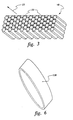
- the first thermally insulative honeycomb assemblage 18 includes a plurality of generally identical cells 20 having a common open direction 22 aligned to extend from the superconductive coil 12 to the vacuum enclosure 14.
- the first thermally insulative honeycomb assemblage 18 is a filamentary-reinforced-epoxy (FRE) composite honeycomb structure whose distance between opposing sides of a cell 20 ranges between generally one millimeter and generally one centimeter.
- the assemblage 18 provides a compression support structure having adequate lateral shear support and a low heat leak. It is noted that conventional support structures for superconducting coils employ discrete tension support members and discrete lateral support members.
- the superconducting device shown in Figures 1 and 2 also includes a thermal shield 24 disposed within and spaced apart from the vacuum enclosure 14 and surrounding and spaced apart from the superconductive coil 12.
- the first thermally insulative honeycomb assemblage 18 is disposed between and connected to the superconductive coil 12 and the thermal shield 24. Such connections may be direct or indirect connections and may be made by mechanical, chemical, or other means as is within the purview of the artisan.
- the first thermally insulative honeycomb assemblage 18 may or may not have a compressive preset depending on a particular application.
- the coil support means 16 also includes a second thermally insulative honeycomb assemblage 26 disposed between and connected to the thermal shield 24 and the vacuum enclosure 14.
- Each honeycomb assemblage 18 and 26 may be a monolithic (i.e., integral) assemblage or may consist of a multiplicity of discrete and spaced-apart or contacting subassemblages.
- the superconducting rotor 10 has an axis of rotation 28 with a midpoint 30, and it is preferred that the connection of the second thermally insulative honeycomb assemblage 26 to the vacuum enclosure 14 be made only proximate the midpoint 30 such as, for example, by support member 32 for proper lateral centering.
- Such midpoint-only connection allows for differential thermal contraction between the cryogenic-temperature thermal shield 24 and the roomtemperature vacuum enclosure 14, as can be appreciated by those skilled in the art.
- the superconductive coil 12 is a racetrack-shaped superconductive coil having a generally longitudinally extending axis 34 disposed generally perpendicular to the axis of rotation 28. It is noted that "racetrack-shape" includes straight sections connected by rounded corners.
- the superconducting rotor 10 shown in Figure 2 is two-pole rotor.
- the superconducting device of the invention in the form of the superconducting rotor 10 of Figure 2 is also applicable to other types of rotors such as multi-pole rotors (not shown in the figures) having a plurality of circumferentially spaced-apart racetrack-shaped superconductive coils whose longitudinally extending axes are disposed generally perpendicular to the axis of rotation.
- each of the superconductive coils of a multi-pole rotor is disposed generally parallel to the circumferential direction of motion of the coil about the axis of rotation while the minor axis of the superconductive coil 12 of the two-pole rotor 10 shown in Figure 2 (or a similar-designed four-pole rotor) is disposed generally perpendicular to the circumferential direction of motion of the coil 12 about the axis of rotation 28.
- Figures 4 and 5 show a second preferred embodiment of the superconducting device of the present invention wherein the Rotor 110 is similar to rotor 10, but rotor 110 has a first thermally insulative suspension strap 136 (shown also in Figure 6) instead of the second thermally insulative honeycomb assemblage 26 of rotor 10.
- the first suspension strap 136 is disposed between and connected to the thermal shield 124 and the vacuum enclosure 114.
- the superconducting rotor 110 includes a thermal station 138 disposed between and directly attached to the superconductive coil 112 and the first thermally insulative honeycomb assemblage 118 with the thermal station 138 having a cooling channel 140 preferably containing gaseous helium at a temperature of generally ten degrees Kelvin.
- a cooling tube 142 is in thermal contact with the thermal shield 124 and preferably contains gaseous helium at a temperature of generally twenty degrees Kelvin.
- the vacuum enclosure 114 is generally at four hundred degrees Kelvin.
- the superconductive coil 112 is a niobium-tin superconductive coil.
- the thermal shield 124 is a generally toroidal-shaped thermal shield generally coaxially aligned with the superconductive coil 112 and having, with respect to the axis of rotation 128 of the superconducting rotor 110, a radially outermost portion 144 and a radially innermost portion 146.
- the vacuum enclosure 114 has, with respect to the axis of rotation 128, a radially outermost portion 148 and a radially innermost portion 150.
- the radially outermost portions 144 and 148 of the thermal shield 124 and the vacuum enclosure 114 are fixedly connected only proximate the midpoint 130 of the axis of rotation 128 such as by support member 152 for proper lateral centering under conditions of differential thermal contraction, as can be appreciated by those skilled in the art.
- the first thermally insulative suspension strap 136 is a generally racetrack-shaped strap connected to the thermal shield 124 proximate the radially outermost portion 144 of the thermal shield 124 and connected to the vacuum enclosure 114 proximate the radially innermost portion 150 of the vacuum enclosure 114.
- the thermal shield 124 has a first pin 154 disposed proximate the radially outermost portion 144 of the thermal shield 124
- the vacuum enclosure 114 has a second pin 156 disposed proximate the radially innermost portion 150 of the vacuum enclosure 114.
- the first and second pins 154 and 156 project, with respect to the axis of rotation 128, along generally opposite circumferential directions.
- the racetrack-shaped strap i.e., the first thermally insulative suspension strap
- the racetrack-shaped strap is disposed to encompass the first and second pins 154 and 156.
- Such an arrangement provides support while allowing for differential thermal contraction between the thermal shield 124 and the vacuum enclosure 114 along the axis of rotation 128 and while minimizing the outer diameter of the vacuum enclosure 114, as can be appreciated by those skilled in the art.
- Tube supports 157 provide lateral support between the vacuum enclosure 114 and the thermal shield 124.
- such tube supports 157 are high strength, low thermal conductivity FRE tubes.
- the superconducting rotors 10 and 110 each have a solid core 58 and 158 made of iron.
- the poles of the superconducting rotor 10 and 110 are considered to include the radially outer portions of the solid core 58 and 158 in the vicinity of the superconductive coil 12 and 112, and the vacuum enclosure 14 and 114 is considered to be the walls of the solid core 58 and 158 which surround the thermal shield 24 and 124 and the superconductive coil 12 and 112.
- the superconductive coils 12 and 112 each are epoxy-impregnated and include a niobium-tin superconductive wire co-paired and cowound with a stainless-steel support wire.
- the honeycomb assemblages 18, 118, and 26 are filamentary-reinforced-epoxy (FRE) honeycomb assemblages, and the suspension strap 136 is a uni-directional FRE suspension strap to minimize heat transfer.
- FRE filamentary-reinforced-epoxy
Landscapes
- Engineering & Computer Science (AREA)
- Power Engineering (AREA)
- Superconductive Dynamoelectric Machines (AREA)
Claims (10)
- Supraleitende Vorrichtung (10, 110) enthaltend:dadurch gekennzeichnet, daß die Einrichtung eine erste thermisch isolierende Honigwabenkonstruktion (18, 118) aufweist, die zwischen der supraleitenden Spule und dem Vakuummantel angeordnet ist.a) eine supraleitende Spule (12, 112),b) einen Vakuummantel (14, 114), der die supraleitende Spule umgibt und im Abstand davon angeordnet ist, undc) eine Einrichtung (16) zum Haltern der supraleitende Spule in dem Vakuummantel während des Betriebs der supraleitenden Vorrichtung,
- Supraleitende Vorrichtung nach Anspruch 1, wobei die erste thermisch isolierende Honigwabenkonstruktion eine Anzahl von im allgemeinen identischen Zellen (20) mit einer gemeinsamen Öffnungsrichtung (22) aufweist, die so ausgerichtet ist, daß sie sich von der supraleitenden Spule zu dem Vakuummantel erstreckt.
- Supraleitende Vorrichtung nach Anspruch 1 oder Anspruch 2, wobei ferner eine thermische Abschirmung (24, 124) vorgesehen ist, die innerhalb und im Abstand von dem Vakuummantel angeordnet ist und die supraleitende Spule umgibt und im Abstand davon angeordnet ist, wobei die erste thermisch isolierende Honigwabenkonstruktion zwischen und verbunden mit der supraleitenden Spule und der thermischen Abschirmung angeordnet ist.
- Supraleitende Vorrichtung nach Anspruch 3, wobei ferner eine zweite thermisch isolierende Honigwabenkonstruktion (26) vorgesehen ist, die zwischen und verbunden mit der supraleitenden Spule und der thermischen Abschirmung angeordnet ist.
- Supraleitende Vorrichtung nach Anspruch 3, wobei ferner ein erstes thermisch isolierendes Aufhängeband (136) vorgesehen ist, das zwischen und verbunden mit der thermischen Abschirmung und dem Vakuummantel angeordnet ist.
- Supraleitende Vorrichtung nach Anspruch 5, wobei die supraleitende Vorrichtung ein supraleitender Rotor ist, der eine Drehachse (28, 128) mit einem Mittelpunkt (30, 130) aufweist, und wobei die supraleitende Spule eine rennstreckenförmige supraleitende Spule mit einer im allgemeinen longitudinal verlaufenden Achse (34) ist, die im allgemeinen senkrecht zu der Drehachse angeordnet ist.
- Supraleitender Rotor nach Anspruch 6, wobei ferner eine thermische Station (138) vorgesehen ist, die zwischen der supraleitenden Spule und der ersten thermisch isolierenden Honigwabenkonstruktion angeordnet und direkt daran befestigt ist, wobei die thermische Station einen Kühlkanal (140) aufweist.
- Supraleitender Rotor nach Anspruch 6 oder Anspruch 7, wobei die thermische Abschirmung eine im allgemeinen toroidförmige thermische Abschirmung ist, die mit der supraleitenden Spule im allgemeinen koaxial ausgerichtet ist und, in bezug auf die Drehachse, einen radial äussersten Abschnitt (144) und einen radial innersten Abschnitt (146) hat, wobei der Vakuummantel, in bezug auf die Drehachse, einen radial äussersten Abschnitt (148) und einen radial innersten Abschnitt (150) hat, und wobei die radail innersten Abschnitte der thermischen Abschirmung und des Vakuummantels nur nahe des Mittelpunktes fest verbunden sind.
- Supraleitender Rotor nach Anspruch 8, wobei das erste thermisch isolierende Aufhängeband ein im allgemeinen rennstreckenförmiges Band ist, das mit der thermischen Abschirmung nahe dem radial äussersten Abschnitt der thermischen abschirmung verbunden und mit dem Vakuummantel nahe dem radial innersten Abschnitt des Vakuummantels verbunden ist.
- Supraleitender Rotor nach Anspruch 9, wobei die thermische Abschirmung einen ersten Stift (154) hat, der nahe dem radial äussersten Abschnitt der thermischen Abschirmung angeordnet ist, wobei der Vakuummantel einen zweiten Stift (156) hat, der nahe dem radial innersten Abschnitt des Vakuummantels angeordnet ist, wobei die ersten und zweiten Stifte, in bezug auf die Drehachse, entlang im allgemeinen entgegengesetzten Umfangsrichtungen vorstehen und wobei das rennstreckenförmige Band so angeordnet ist, daß es die ersten und zweiten Stifte umschließt.
Priority Applications (2)
| Application Number | Priority Date | Filing Date | Title |
|---|---|---|---|
| EP96303077A EP0805546B1 (de) | 1996-05-01 | 1996-05-01 | Trägerstruktur für eine supraleitende Wicklung |
| DE69618342T DE69618342T2 (de) | 1996-05-01 | 1996-05-01 | Trägerstruktur für eine supraleitende Wicklung |
Applications Claiming Priority (1)
| Application Number | Priority Date | Filing Date | Title |
|---|---|---|---|
| EP96303077A EP0805546B1 (de) | 1996-05-01 | 1996-05-01 | Trägerstruktur für eine supraleitende Wicklung |
Publications (2)
| Publication Number | Publication Date |
|---|---|
| EP0805546A1 EP0805546A1 (de) | 1997-11-05 |
| EP0805546B1 true EP0805546B1 (de) | 2002-01-02 |
Family
ID=8224914
Family Applications (1)
| Application Number | Title | Priority Date | Filing Date |
|---|---|---|---|
| EP96303077A Expired - Lifetime EP0805546B1 (de) | 1996-05-01 | 1996-05-01 | Trägerstruktur für eine supraleitende Wicklung |
Country Status (2)
| Country | Link |
|---|---|
| EP (1) | EP0805546B1 (de) |
| DE (1) | DE69618342T2 (de) |
Cited By (2)
| Publication number | Priority date | Publication date | Assignee | Title |
|---|---|---|---|---|
| DE10303307A1 (de) * | 2003-01-28 | 2004-08-26 | Siemens Ag | Maschine mit einem Rotor und einer supraleltenden Rotorwicklung |
| DE102004039855A1 (de) * | 2004-08-17 | 2006-03-09 | Siemens Ag | Maschine mit einer Erregerwicklung aus Hoch-Tc-Supraleitern in einer Halteeinrichtung |
Family Cites Families (2)
| Publication number | Priority date | Publication date | Assignee | Title |
|---|---|---|---|---|
| JP2856946B2 (ja) * | 1991-05-31 | 1999-02-10 | 株式会社東芝 | 超電導磁石 |
| US5548168A (en) * | 1994-06-29 | 1996-08-20 | General Electric Company | Superconducting rotor for an electrical machine |
-
1996
- 1996-05-01 DE DE69618342T patent/DE69618342T2/de not_active Expired - Fee Related
- 1996-05-01 EP EP96303077A patent/EP0805546B1/de not_active Expired - Lifetime
Cited By (4)
| Publication number | Priority date | Publication date | Assignee | Title |
|---|---|---|---|---|
| DE10303307A1 (de) * | 2003-01-28 | 2004-08-26 | Siemens Ag | Maschine mit einem Rotor und einer supraleltenden Rotorwicklung |
| US7741738B2 (en) | 2003-01-28 | 2010-06-22 | Siemens Aktiengesellschaft | Machine comprising a rotor and a superconducting rotor winding |
| DE10303307B4 (de) * | 2003-01-28 | 2010-12-30 | Siemens Ag | Maschine mit einem Rotor und einer supraleltenden Rotorwicklung |
| DE102004039855A1 (de) * | 2004-08-17 | 2006-03-09 | Siemens Ag | Maschine mit einer Erregerwicklung aus Hoch-Tc-Supraleitern in einer Halteeinrichtung |
Also Published As
| Publication number | Publication date |
|---|---|
| DE69618342D1 (de) | 2002-02-07 |
| EP0805546A1 (de) | 1997-11-05 |
| DE69618342T2 (de) | 2002-08-29 |
Similar Documents
| Publication | Publication Date | Title |
|---|---|---|
| US5532663A (en) | Support structure for a superconducting coil | |
| US5672921A (en) | Superconducting field winding assemblage for an electrical machine | |
| US7741738B2 (en) | Machine comprising a rotor and a superconducting rotor winding | |
| US6856062B2 (en) | Homopolar machine with shaft axial thrust compensation for reduced thrust bearing wear and noise | |
| US5774032A (en) | Cooling arrangement for a superconducting coil | |
| CA1103297A (en) | Stored field superconducting electrical machine and method | |
| US8841980B2 (en) | Coil with superconductive windings cooled without cryogenic fluids | |
| US6605886B2 (en) | High temperature superconductor synchronous rotor coil support insulator | |
| US4277705A (en) | Method and apparatus for cooling a winding in the rotor of an electrical machine | |
| EP0805545B1 (de) | Zusammenstellung einer supraleitenden Feldwicklung für eine elektrische Maschine | |
| US7834510B2 (en) | Torque support member for rotating electrical machine | |
| EP1261116B1 (de) | Spulenträger für hochtemperatursupraleitenden Synchronrotor mit Zugankern | |
| US6628033B1 (en) | Reduction of induced magnetic forces on current collectors in homopolar machines having high magnetic fields | |
| US6617714B2 (en) | High temperature super-conducting coils supported by an iron core rotor | |
| JP3972964B2 (ja) | 界磁巻線集成体 | |
| US6590308B2 (en) | High power density super-conducting electric machine | |
| EP0805546B1 (de) | Trägerstruktur für eine supraleitende Wicklung | |
| Oberhauser et al. | Some considerations in the design of a superconducting alternator | |
| US6787967B2 (en) | High temperature super-conducting rotor coil support and coil support method | |
| JP3874836B2 (ja) | 超伝導装置 | |
| Singh et al. | Conceptual design of a high temperature superconducting generator | |
| US20260024689A1 (en) | Superconducting compact energy cell (cec) | |
| Bogner | Applied superconductivity activities at siemens |
Legal Events
| Date | Code | Title | Description |
|---|---|---|---|
| PUAI | Public reference made under article 153(3) epc to a published international application that has entered the european phase |
Free format text: ORIGINAL CODE: 0009012 |
|
| AK | Designated contracting states |
Kind code of ref document: A1 Designated state(s): DE FR GB |
|
| 17P | Request for examination filed |
Effective date: 19980506 |
|
| 17Q | First examination report despatched |
Effective date: 19990729 |
|
| GRAG | Despatch of communication of intention to grant |
Free format text: ORIGINAL CODE: EPIDOS AGRA |
|
| GRAG | Despatch of communication of intention to grant |
Free format text: ORIGINAL CODE: EPIDOS AGRA |
|
| GRAH | Despatch of communication of intention to grant a patent |
Free format text: ORIGINAL CODE: EPIDOS IGRA |
|
| GRAH | Despatch of communication of intention to grant a patent |
Free format text: ORIGINAL CODE: EPIDOS IGRA |
|
| GRAA | (expected) grant |
Free format text: ORIGINAL CODE: 0009210 |
|
| REG | Reference to a national code |
Ref country code: GB Ref legal event code: IF02 |
|
| AK | Designated contracting states |
Kind code of ref document: B1 Designated state(s): DE FR GB |
|
| REF | Corresponds to: |
Ref document number: 69618342 Country of ref document: DE Date of ref document: 20020207 |
|
| ET | Fr: translation filed | ||
| PLBE | No opposition filed within time limit |
Free format text: ORIGINAL CODE: 0009261 |
|
| STAA | Information on the status of an ep patent application or granted ep patent |
Free format text: STATUS: NO OPPOSITION FILED WITHIN TIME LIMIT |
|
| 26N | No opposition filed | ||
| PGFP | Annual fee paid to national office [announced via postgrant information from national office to epo] |
Ref country code: DE Payment date: 20080630 Year of fee payment: 13 |
|
| PGFP | Annual fee paid to national office [announced via postgrant information from national office to epo] |
Ref country code: GB Payment date: 20080529 Year of fee payment: 13 |
|
| GBPC | Gb: european patent ceased through non-payment of renewal fee |
Effective date: 20090501 |
|
| REG | Reference to a national code |
Ref country code: FR Ref legal event code: ST Effective date: 20100129 |
|
| PG25 | Lapsed in a contracting state [announced via postgrant information from national office to epo] |
Ref country code: FR Free format text: LAPSE BECAUSE OF NON-PAYMENT OF DUE FEES Effective date: 20090602 |
|
| PGFP | Annual fee paid to national office [announced via postgrant information from national office to epo] |
Ref country code: FR Payment date: 20080519 Year of fee payment: 13 |
|
| PG25 | Lapsed in a contracting state [announced via postgrant information from national office to epo] |
Ref country code: GB Free format text: LAPSE BECAUSE OF NON-PAYMENT OF DUE FEES Effective date: 20090501 |
|
| PG25 | Lapsed in a contracting state [announced via postgrant information from national office to epo] |
Ref country code: DE Free format text: LAPSE BECAUSE OF NON-PAYMENT OF DUE FEES Effective date: 20091201 |