EP0805079B1 - Pedal support structure for a vehicle - Google Patents
Pedal support structure for a vehicle Download PDFInfo
- Publication number
- EP0805079B1 EP0805079B1 EP97107073A EP97107073A EP0805079B1 EP 0805079 B1 EP0805079 B1 EP 0805079B1 EP 97107073 A EP97107073 A EP 97107073A EP 97107073 A EP97107073 A EP 97107073A EP 0805079 B1 EP0805079 B1 EP 0805079B1
- Authority
- EP
- European Patent Office
- Prior art keywords
- pedal
- vehicle
- center shaft
- swing
- bracket
- Prior art date
- Legal status (The legal status is an assumption and is not a legal conclusion. Google has not performed a legal analysis and makes no representation as to the accuracy of the status listed.)
- Expired - Lifetime
Links
- 238000006073 displacement reaction Methods 0.000 claims description 9
- 239000000725 suspension Substances 0.000 claims description 6
- 230000005540 biological transmission Effects 0.000 claims description 5
- 230000002093 peripheral effect Effects 0.000 claims description 5
- 238000013459 approach Methods 0.000 claims description 2
- 210000003127 knee Anatomy 0.000 description 11
- 230000001012 protector Effects 0.000 description 6
- 210000002414 leg Anatomy 0.000 description 4
- 238000005452 bending Methods 0.000 description 3
- 239000012530 fluid Substances 0.000 description 2
- 230000033001 locomotion Effects 0.000 description 2
- 230000000694 effects Effects 0.000 description 1
- 230000001771 impaired effect Effects 0.000 description 1
- 239000011810 insulating material Substances 0.000 description 1
- 239000012212 insulator Substances 0.000 description 1
- 239000000463 material Substances 0.000 description 1
- 239000013589 supplement Substances 0.000 description 1
Images


Classifications
-
- G—PHYSICS
- G05—CONTROLLING; REGULATING
- G05G—CONTROL DEVICES OR SYSTEMS INSOFAR AS CHARACTERISED BY MECHANICAL FEATURES ONLY
- G05G1/00—Controlling members, e.g. knobs or handles; Assemblies or arrangements thereof; Indicating position of controlling members
- G05G1/30—Controlling members actuated by foot
- G05G1/32—Controlling members actuated by foot with means to prevent injury
-
- B—PERFORMING OPERATIONS; TRANSPORTING
- B60—VEHICLES IN GENERAL
- B60R—VEHICLES, VEHICLE FITTINGS, OR VEHICLE PARTS, NOT OTHERWISE PROVIDED FOR
- B60R21/00—Arrangements or fittings on vehicles for protecting or preventing injuries to occupants or pedestrians in case of accidents or other traffic risks
- B60R21/02—Occupant safety arrangements or fittings, e.g. crash pads
- B60R21/09—Control elements or operating handles movable from an operative to an out-of-the way position, e.g. pedals, switch knobs, window cranks
-
- B—PERFORMING OPERATIONS; TRANSPORTING
- B60—VEHICLES IN GENERAL
- B60T—VEHICLE BRAKE CONTROL SYSTEMS OR PARTS THEREOF; BRAKE CONTROL SYSTEMS OR PARTS THEREOF, IN GENERAL; ARRANGEMENT OF BRAKING ELEMENTS ON VEHICLES IN GENERAL; PORTABLE DEVICES FOR PREVENTING UNWANTED MOVEMENT OF VEHICLES; VEHICLE MODIFICATIONS TO FACILITATE COOLING OF BRAKES
- B60T7/00—Brake-action initiating means
- B60T7/02—Brake-action initiating means for personal initiation
- B60T7/04—Brake-action initiating means for personal initiation foot actuated
- B60T7/06—Disposition of pedal
- B60T7/065—Disposition of pedal with means to prevent injuries in case of collision
-
- Y—GENERAL TAGGING OF NEW TECHNOLOGICAL DEVELOPMENTS; GENERAL TAGGING OF CROSS-SECTIONAL TECHNOLOGIES SPANNING OVER SEVERAL SECTIONS OF THE IPC; TECHNICAL SUBJECTS COVERED BY FORMER USPC CROSS-REFERENCE ART COLLECTIONS [XRACs] AND DIGESTS
- Y10—TECHNICAL SUBJECTS COVERED BY FORMER USPC
- Y10T—TECHNICAL SUBJECTS COVERED BY FORMER US CLASSIFICATION
- Y10T74/00—Machine element or mechanism
- Y10T74/20—Control lever and linkage systems
- Y10T74/20528—Foot operated
Definitions
- the present invention relates to a pedal support structure for a vehicle.
- JP-A Japanese Utility Model Application Laid-Open
- a steering column 402 covering a steering shaft 400 is supported on the vehicle body side via a tilt bracket 408 comprised of an upper plate member 404 and a pair of side plate members 406, as well as via a shaft 410, which penetrates through the side plate members 406 so as to support the bottom edge of the steering column 402.
- an elastically deformable knee protector 412 having a substantially arc shape is disposed under the above-described tilt bracket 408.
- This knee protector 412 is elastically supported on the lower side of the steering column 402 via an elastically deformable stay 414.
- the above-described structure employing the knee protector 412 may be effective as countermeasures in cases where an external force greater than a predetermined value acting on the vehicle from the front side thereof.
- US-A-3 025 713 discloses a brake actuating mechanism for motor vehicles which comprises foot operated service brakes and hand operated emergency brakes and utilizes, in the case that the service brakes should, due to a lack of hydraulic pressure, fail to function, the extended length of the pedal stroke to operate the mechanical emergency brakes.
- EPC describes a supporting structure of a pedal device for a vehicle which includes a pedal bracket and a displacement controlling device.
- the pedal bracket is fixed to the vehicle body and supports a rotating shaft portion of a suspended-type pedal device.
- the displacement controlling device transmits an external force of a predetermined value or greater to the rotating shaft portion when the external force is applied to a front portion of the vehicle and controls the displacement of a foot pad of the pedal device such that the rotating shaft portion is moved substantially toward the rear of the vehicle.
- a pedal support structure for a vehicle capable of controlling the displacement of the pad of a vehicle pedal when an external force greater than a predetermined value acts on the vehicle from the front side thereof.
- a pedal support structure for a vehicle comprising: a pedal bracket fixed on a vehicle body and supporting a rotation-center shaft of a suspension type vehicle pedal; a swing link which is supported by the pedal bracket in a manner swingable about a swing-center shaft and one end portion of which is connected to operating-force transmission means for transmitting a treading force applied to the pad of the vehicle pedal to treading-force boosting means; a connecting link which connects the other end portion of the swing link and one end portion of the vehicle pedal opposite to the pad in a relatively rotatable manner, which transmits a rotational force of the vehicle pedal, generated about a rotation-center shaft of the vehicle pedal and toward the front of the vehicle, to the operating-force transmission means via the swing link, and in which a connecting pin for connection with the end portion of the vehicle pedal opposite to the pad is offset substantially toward the front of the vehicle from a line connecting the rotation-center shaft of the vehicle pedal and the swing-center shaft of the swing link; and displacement control
- releasing means for releaseing the connection, established by the connecting link, between the other end portion of the swing link and the end portion of the vehicle pedal opposite to the pad when the distance between the rotation-center shaft and the swing-center shaft increases.
- the displacement control means when an external force greater than a predetermined value acts on the front portion of the vehicle, causes the distance between the rotation-center shaft of the vehicle pedal and the swing-center shaft of the swing link to increase. Further, in this case, the connecting pin of the connecting link, which is offset substantially toward the front of the vehicle or toward the top of the vehicle from the line connecting the rotation-center shaft of the vehicle pedal and the swing-center shaft of the swing link, is displaced toward the line. Thus, a torque is applied to the vehicle pedal so as to turn the vehicle pedal about the rotation-center shaft toward the front of the vehicle. In this manner, the displacement of the pad of the vehicle pedal is controlled when an external force greater than a predetermined value acts on the vehicle from the front side thereof.
- the displacement control means causes the second bracket disposed above the first bracket supporting the rotation-center shaft of the vehicle pedal to move away from the first bracket. Since the swing-center shaft of the swing link is supported by the second bracket, the distance between the swing-center shaft of the swing link and the rotation-center shaft of the vehicle pedal increases as the second bracket moves away from the first bracket.
- the releasing means releases the connection, established by the connecting link, between the other end portion of the swing link and the end portion of the vehicle pedal opposite to the pad. Accordingly, the vehicle pedal is released from the connecting link, thereby utilizing an inertial force directed substantially toward the front of the vehicle and acting on the vehicle pedal for displacing the pad of the vehicle pedal when an external force greater than a predetermined value acts on the vehicle from the front side thereof.
- FIGS. 1 and 2 A first embodiment of the present invention will now be described with reference to FIGS. 1 and 2.
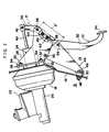
- FIG. 1 schematically-shows the side view of a suspension type brake pedal 10 and its peripheral structure.
- a dash panel 16 is substantially vertically disposed so as to separate an engine room 12 from a compartment space 14.
- a brake booster 18 for boosting a treading force applied by an occupant to the brake pedal 10
- a master cylinder 20 for converting a pressure boosted by the brake booster 18 to a fluid pressure
- a reservoir tank 22 for storing and replenishing brake fluid in accordance with a change of volume of a hydraulic system.
- a link support 24 is disposed on the rear side of the dash panel 16.
- This link support 24 comprises a base plate 26 and a side plate 28.
- the base plate 26 is disposed in parallel with the dash panel 16.
- the side plate 28, having a substantially rectangular shape, is supported by the base plate 26 in a cantilever manner and extends toward the rear of the vehicle such that its plane is oriented along the longitudinal direction of the vehicle.
- a plurality of cylindrical collars 30 are fixed on the front-side surface of the base plate 26 of the link support 24 at predetermined positions. These collars 30 abut the dash panel 16 such that stud bolts 32 projecting from the brake booster 18 are inserted into the corresponding collars 30. Nuts 34 are screwed onto the stud bolts 32 from the compartment side, so that the link support 24 is fixed onto the dash panel 16.
- An unillustrated dash insulator serving as a noise insulating material, is interposed between the dash panel 16 and the base plate 26. Alternatively, nuts may be welded onto the front-side surface of the dash panel 16, and mounting bolts may be passed through the base plate 26 and screwed into the welded nuts to thereby fix the base plate 26 onto the dash panel 16.
- a swing-center shaft 38 for a swing link 36 is supported by the link support 24 at its rear end portion.
- the swing-center shaft 38 is located at the intermediate portion of the swing link 36.
- the upper end portion of the swing link 36 is connected to the tip portion of a push rod 40 projecting from the brake booster 18 such that the swing link 36 can rotate about a hinge pin 42 located at the tip portion of the push rod 40.
- a pedal support 44 having a substantially triangular shape as viewed from its side, is disposed under the link support 24.
- Cylindrical collars 30 are fixed on the front-side surface of the bottom end portion of the pedal support 44 at predetermined positions. The collars 30 also abut the dash panel 16.
- Mounting bolts 48 are inserted into the collars 30 from the compartment side and are screwed into nuts 46 welded onto the front-side surface of the dash panel 16, thereby fixing the pedal support 44 onto the dash panel 16.
- the upper front end portion of the pedal support 44 and the lower front end portion of the link support 24 are pivotably connected by a support shaft 50.
- a rotation-center shaft 56 of the brake pedal 10 is supported by the pedal support 44 at its upper rear end portion.
- the brake pedal 10 comprises a pedal support member 52 formed by adequately bending a narrow plate material and a pedal pad 54 attached to the bottom end portion of the pedal support member 52.
- the rotation-center shaft 56 is located at the intermediate portion of the pedal support member 52 offset toward the top end of the pedal support member 52.
- the rotation-center shaft 56 is pivotably engaged with a cut-away portion 58 having an inverse U-shape and formed in the side plate 28 of the link support 24 at its lower rear end portion.
- the upper end portion of the pedal support member 52 and the lower end portion of the swing link 36 are pivotably connected via a straight connecting link 60.
- the front end portion of the connecting link 60 and the upper end portion of the pedal support member 52 are hinged by a first connecting pin 62
- the rear end portion of the connecting link 60 and the lower end portion of the swing link 36 are hinged by a second connecting pin 64.
- the first connecting pin 62 is offset substantially toward the front of the vehicle from a line P connecting the rotation-center shaft 56 of the brake pedal 10 and the swing-center shaft 38 of the swing link 36.
- the brake pedal 10 In an ordinary traveling state of the vehicle, the brake pedal 10 is held at its initial position by the urging force of a return spring. In this state, when a occupant applies a treading force to the pedal pad 54 of the brake pedal 10, the brake pedal 10 swings about the rotation-center shaft 56 toward the front of the vehicle. This swing motion is transmitted to the swing link 36 via the connecting link 60, thereby causing the swing link 36 to swing about the swing-center shaft 38 in a counterclockwise direction on FIG. 1. This causes the push rod 40 to be pushed substantially toward the front of the vehicle. As a result, the treading force applied to the pedal pad 54 by the occupant is boosted by the brake booster 18.
- the connecting link 60 is substantially aligned with the line P connecting the rotation-center shaft 56 and the swing-center shaft 38. That is, in addition to the second connecting pin 64, which connects the connecting link 60 and the swing link 36, the first connecting pin 62, which connects the connecting link 60 and the pedal support member 52, is drawn toward the line P. As a result, a torque is applied to the brake pedal 10 such that the brake pedal 10 turns about the rotation-center shaft 56 so as to move the pedal pad 54 substantially toward the front of the vehicle.
- the swing link 36 and the brake pedal 10 are connected by the connecting link 60, and the link support 24, which supports the swing-center shaft 38 of the swing link 36, is separably engaged with the pedal support 44, which supports the rotation-center shaft 56 of the brake pedal 10.
- the first connecting pin 62 which connects the connecting link 60 and the brake pedal 10 is offset substantially toward the front of the vehicle from the line P connecting the rotation-center shaft 56 and the swing-center shaft 38. Therefore, when an external force greater than the predetermined value acts on the vehicle from the front side thereof, the distance between the rotation-center shaft 56 and the swing-center shaft 38 is increased from A to A', so that the first connecting pin 62 can be drawn toward the line P.
- the pedal pad 54 of the brake pedal 10 can be displaced substantially toward the front of the vehicle.
- the associated deformation of the dash panel 16 is utilized for displacing the pedal pad 54 substantially toward the front of the vehicle.
- the pedal bracket is divided into the link support 24, which supports the swing-center shaft 38 of the swing link 36, and the pedal support 44, which supports the rotation-center shaft 56 of the brake pedal 10. Therefore, when an external force greater than the predetermined value acts on the vehicle from the front side thereof, the distance between the rotation-center shaft 56 and the swing-center shaft 38 can be increased merely by turning the link support 24 relative to the pedal-support 44 about the support shaft 50. That is, the distance between the rotation-center shaft 56 and the swing-center shaft 38 can be increased through the employment of a simple structure. In other words, the present embodiment provides a simple structure.
- the pedal bracket comprises two separate members, i.e. the link support 24 and the pedal support 44.
- the link support 24 and the pedal support 44 may be formed as a single member.
- a crack-generating portion such as a slit, a thin-walled portion, or the like may be provided so that a portion corresponding to the link support 24 can separate from a portion corresponding to the pedal support 44 when an external force greater than the predetermined value acts on the vehicle from the front side thereof.
- FIG. 3 is an enlarged side view of a main portion of the present embodiment.
- the hole 70 formed for engagement with the first connecting pin 62 has a keyhole-like shape such that it is open to the exterior of the connecting link 60.
- the peripheral portion of the hole 70 does not plastically deform during ordinary braking operation, so that ordinary braking operation is not hindered.
- the link support 24 turns upward about the support shaft 50 in a manner similar to that of the first embodiment. Accordingly, there increases the distance between the rotation-center shaft 56 of the brake pedal 10 and the swing-center shaft 38 of the swing link 36.
- the present invention is not limited thereto. Only a hole to be engaged with the second connecting pin 64 or both holes may be formed into a keyhole-like shape.
- the connecting link 60 is allowed to break away, as needed, from the first connecting pin 62.
- the present invention is not limited thereto.
- a cut-away portion or a thin-walled portion may be provided in the connecting link 60 at its intermediate portion, so that the connecting link 60 breaks at its intermediate portion.
Landscapes
- Engineering & Computer Science (AREA)
- Mechanical Engineering (AREA)
- Transportation (AREA)
- Physics & Mathematics (AREA)
- General Physics & Mathematics (AREA)
- Automation & Control Theory (AREA)
- Braking Elements And Transmission Devices (AREA)
- Mechanical Control Devices (AREA)
- Body Structure For Vehicles (AREA)
Description
Claims (8)
- A pedal support structure for a vehicle comprising:wherein said pedal bracket includes a first pedal bracket portion (44) and a second bracket portion (24), said first pedal bracket portion (44) supporting said rotation-center shaft (56) of said vehicle pedal (10) and said second pedal bracket portion (24) supporting said swing-center shaft (38) of said swing link (36) and located above said first bracket portion (44).a pedal bracket fixed on a vehicle body and supporting a rotation-center shaft (56) of a suspension type vehicle pedal (10);a swing link (36) which is supported by said pedal bracket in a manner swingable about a swing-center shaft (38), one end portion of said swing link (36) being connected to operating-force transmission means which transmits a treading force applied to the pad (54) of the vehicle pedal (10) to treading-force boosting means;a connecting link (60) which connects the other end portion of said swing link (36) and one end portion of said vehicle pedal (10) opposite to the pad (54) in a relatively rotatable manner, said connecting link (60) transmitting a rotational force of said vehicle pedal (10), generated about said rotation-center shaft (56) toward the front of the vehicle, to said operating-force transmission means via said swing link (36), and a connecting pin (62) of said connecting link (60) for connection with the end portion of said vehicle pedal (10) opposite to the pad (54) being offset substantially toward the front of the vehicle from a line connecting said rotation-center shaft (56) of said vehicle pedal (10) and said swing-center shaft (38) of said swing link (36); anddisplacement control means which operates, when an external force greater than a predetermined value acts on the front portion of the vehicle, so as to increase the distance between said rotation-center shaft (56) and said swing-center shaft (38) and to move said connecting pin (62) such that said connecting pin (62) approaches the line, thereby displacing the pad (54) of said vehicle pedal (10),
- A pedal support structure for a vehicle according to Claim 1, characterized in that said treading-force boosting means is a brake booster (18), and said operating-force transmission means is a push rod (40) projecting from said brake booster (18).
- A pedal support structure for a vehicle according to Claim 1 or 2, characterized in that an upper front end portion of said first bracket (44) is connected to a lower front end portion of said second bracket (24) via a rotary support shaft (50) in a relatively rotatable manner.
- A pedal support structure for a vehicle according to Claim 3, characterized in that an inverse-U-shaped cut-away portion (58) is formed in a lower rear end portion of said second bracket (24), and said rotation-center shaft (56) of said vehicle pedal (10) provided on said first bracket (44) is engaged with said cut-away portion (58) in a relatively rotatable manner.
- A pedal support structure for a vehicle according to Claim 1 or 2, characterized in that said first and second brackets (44, 24) are formed as a single member having a crack-generating portion so that a portion of said member corresponding to said second bracket (24) separates from a portion of said member corresponding to said first bracket (44) when an external force greater than the predetermined value acts on the vehicle from the front side thereof.
- A pedal support structure for a vehicle according to any one of Claims 1 - 5, characterized by further comprising releasing means for releasing the connection, established by said connecting link (60), between the other end portion of said swing link (36) and the end portion of said vehicle pedal (10) opposite to the pad (54) when the distance between said rotation-center shaft (56) and said swing-center shaft (38) increases.
- A pedal support structure for a vehicle according to Claim 6, characterized in that at least one of the holes that are formed at the opposite ends of said connecting link (60) for engagement with said connecting pin (62) and a second connecting pin (64) for connection with the other end of said swing link (36) is formed in a keyhole-like shape which is opened to the peripheral edge of said connecting link (60), thereby constituting said releasing means.
- A pedal support structure for a vehicle according to Claim 6, characterized in that said releasing means is a crack-generating portion provided in said connecting link (60) at its intermediate portion.
Applications Claiming Priority (3)
| Application Number | Priority Date | Filing Date | Title |
|---|---|---|---|
| JP10977596 | 1996-04-30 | ||
| JP08109775A JP3125677B2 (en) | 1996-04-30 | 1996-04-30 | Vehicle pedal support structure |
| JP109775/96 | 1996-04-30 |
Publications (3)
| Publication Number | Publication Date |
|---|---|
| EP0805079A2 EP0805079A2 (en) | 1997-11-05 |
| EP0805079A3 EP0805079A3 (en) | 1998-05-13 |
| EP0805079B1 true EP0805079B1 (en) | 2003-06-11 |
Family
ID=14518920
Family Applications (1)
| Application Number | Title | Priority Date | Filing Date |
|---|---|---|---|
| EP97107073A Expired - Lifetime EP0805079B1 (en) | 1996-04-30 | 1997-04-29 | Pedal support structure for a vehicle |
Country Status (4)
| Country | Link |
|---|---|
| US (1) | US5848558A (en) |
| EP (1) | EP0805079B1 (en) |
| JP (1) | JP3125677B2 (en) |
| DE (1) | DE69722710T2 (en) |
Families Citing this family (60)
| Publication number | Priority date | Publication date | Assignee | Title |
|---|---|---|---|---|
| JP3454014B2 (en) * | 1995-08-31 | 2003-10-06 | トヨタ自動車株式会社 | Vehicle pedal support structure |
| DE19606427A1 (en) * | 1996-02-22 | 1997-08-28 | Teves Gmbh Alfred | Brake pedal mechanism for motor vehicles |
| JP3239751B2 (en) * | 1996-04-30 | 2001-12-17 | トヨタ自動車株式会社 | Vehicle pedal support structure |
| JPH10181637A (en) * | 1996-12-25 | 1998-07-07 | Toyota Motor Corp | Vehicle pedal displacement control structure |
| DE19706692C1 (en) * | 1997-02-20 | 1998-06-18 | Daimler Benz Ag | Automobile foot-well control pedal |
| JP3125715B2 (en) * | 1997-05-23 | 2001-01-22 | トヨタ自動車株式会社 | Vehicle pedal displacement control structure |
| DE19733512C2 (en) * | 1997-08-03 | 2003-12-11 | Scharwaechter Gmbh Co Kg | safety device |
| BR9803209A (en) * | 1997-08-27 | 1999-10-13 | Scharwaechter Ed Gmbh | Safety set for mounting pedals in motor vehicles |
| JP3542709B2 (en) * | 1998-01-13 | 2004-07-14 | 株式会社ヨロズ | Automotive brake pedal device |
| EP0928726B8 (en) * | 1998-01-13 | 2006-06-28 | Nissan Motor Co., Ltd. | Brake pedal structure for vehicle |
| JP3449206B2 (en) * | 1998-02-04 | 2003-09-22 | トヨタ自動車株式会社 | Vehicle pedal displacement control structure |
| US6089119A (en) * | 1998-03-23 | 2000-07-18 | Bosch Systemes De Freinage | Motor vehicle pedal arrangement |
| DE19839521C1 (en) * | 1998-08-29 | 2000-03-09 | Daimler Chrysler Ag | Stem structure for a motor vehicle |
| GB9819308D0 (en) | 1998-09-05 | 1998-10-28 | Rover Group | Vehicle control pedals |
| US6070489A (en) * | 1998-10-26 | 2000-06-06 | Teleflex Incorporated | Mounting assembly for an adjustable pedal |
| DE19957571B4 (en) * | 1998-12-07 | 2012-02-16 | Schaeffler Technologies Gmbh & Co. Kg | Arrangement for receiving a pedal |
| DE19919749C2 (en) * | 1999-04-29 | 2002-05-02 | Zf Lemfoerder Metallwaren Ag | Brake pedal mechanism for motor vehicles |
| US6431022B1 (en) | 1999-11-23 | 2002-08-13 | Edmond Burton Cicotte | Compact adjustable pedal system |
| GB9930601D0 (en) * | 1999-12-24 | 2000-02-16 | Ksr Automotive Limited | Vehicle pedal box |
| US6565160B1 (en) | 2000-02-15 | 2003-05-20 | Ford Global Technologies, Inc. | Pressure releasable vehicle pedal assembly |
| US6655230B1 (en) | 2000-02-23 | 2003-12-02 | Ford Global Technologies, Llc | Vehicle pedal assembly |
| US20030075005A1 (en) * | 2000-04-04 | 2003-04-24 | Lothar Schiel | Crash-safe pedals in a vehicle |
| DE10017794B4 (en) * | 2000-04-10 | 2009-05-07 | Fico Cables, S.A., Rubi | Pedal security system |
| US6286388B1 (en) | 2000-04-11 | 2001-09-11 | Ford Global Technologies, Inc. | Vehicle pedal assembly |
| US6679135B1 (en) | 2000-09-14 | 2004-01-20 | Trw Vehicle Safety Systems Inc. | Energy absorbing brake pedal |
| WO2002055353A2 (en) * | 2001-01-10 | 2002-07-18 | Ksr International, Inc. | Brake pedal assembly with variable ratio |
| FR2822120B1 (en) * | 2001-03-19 | 2003-12-12 | Renault | IMPROVEMENT TO A DEVICE FOR MOUNTING A PEDAL IN A VEHICLE |
| JP2003025864A (en) * | 2001-07-17 | 2003-01-29 | Nissan Motor Co Ltd | Mounting structure of accelerator pedal device |
| JP3920673B2 (en) | 2001-07-24 | 2007-05-30 | 豊田鉄工株式会社 | Vehicle pedal retreat prevention device |
| GB2391203A (en) * | 2002-07-26 | 2004-02-04 | Ford Global Tech Inc | Pedal lever assembly for a motor vehicle |
| US6951152B2 (en) * | 2003-02-17 | 2005-10-04 | Dura Global Technologies, Inc. | Crash release arrangement and method for an automotive pedal mounting |
| GB0310510D0 (en) * | 2003-05-08 | 2003-06-11 | Bck Technology Ltd | Arrangement for permitting motor vehicle foot pedal release and motor vehicle incorporating same |
| US7195091B2 (en) * | 2003-08-06 | 2007-03-27 | Drivesol Worldwide, Inc. | Crash relief pedal assembly |
| JP4029800B2 (en) * | 2003-08-26 | 2008-01-09 | マツダ株式会社 | Automobile pedal support structure |
| KR100507224B1 (en) * | 2003-10-10 | 2005-08-10 | 현대자동차주식회사 | Assembley of brake pedal for automobile |
| KR100552747B1 (en) * | 2003-11-13 | 2006-02-20 | 현대자동차주식회사 | Ankle prevention structure of automobile brake pedal |
| JP2005153603A (en) * | 2003-11-21 | 2005-06-16 | F Tech:Kk | Operation pedal support device for automobiles |
| US20050166703A1 (en) * | 2004-01-29 | 2005-08-04 | Nebojsa Djordjevic | Variable rate control pedal |
| US7415909B2 (en) * | 2004-03-31 | 2008-08-26 | Mazda Motor Corporation | Support structure for pedal of vehicle |
| DE102004030267B4 (en) * | 2004-06-23 | 2006-07-13 | Bayerische Motoren Werke Ag | Method for damping axial impacts on a driver's lower extremity |
| EP1640229B1 (en) * | 2004-09-27 | 2007-01-24 | Mazda Motor Corporation | Pedal assembly support structure for vehicle |
| DE102005010809B4 (en) * | 2005-03-07 | 2007-04-26 | Daimlerchrysler Ag | Stem of a motor vehicle |
| JP4394031B2 (en) * | 2005-04-12 | 2010-01-06 | 豊田鉄工株式会社 | Brake pedal device |
| JP4500739B2 (en) * | 2005-07-01 | 2010-07-14 | 豊田鉄工株式会社 | Vehicle pedal retreat prevention device |
| ES2283195B1 (en) * | 2005-09-22 | 2008-08-16 | Universitat Politecnica De Catalunya | COLLAPSABLE CLUTCH PEDAL SYSTEM IN AUTOMOBILE VEHICLES. |
| US20070137398A1 (en) * | 2005-11-17 | 2007-06-21 | Mazda Motor Corporation | Support structure for control pedal |
| JP4764702B2 (en) * | 2005-11-17 | 2011-09-07 | マツダ株式会社 | Operation pedal support structure |
| US7712570B2 (en) * | 2006-06-08 | 2010-05-11 | Honda Motor Co., Ltd. | Crash safe vehicle brake assembly |
| US7726611B2 (en) * | 2006-06-30 | 2010-06-01 | Honeywell International Inc. | Active rudder pedal mechanism with foreign object strike tolerance and articulating brake |
| US20080053265A1 (en) * | 2006-09-01 | 2008-03-06 | Bannon Sean A | Pedal assembly |
| US7775555B2 (en) * | 2008-04-04 | 2010-08-17 | Dura Global Technologies, Llc | Break-away pedal assembly |
| FR2944115B1 (en) | 2009-04-07 | 2015-06-05 | Coutier Moulage Gen Ind | AUTOMOTIVE VEHICLE PEDAL WITH SAFETY DEVICE. |
| JP2013502344A (en) * | 2009-08-18 | 2013-01-24 | ケイエスアール テクノロジーズ カンパニー | Brake pedal assembly with non-contact sensor |
| US8806976B2 (en) | 2010-02-04 | 2014-08-19 | Ksr Technologies Co. | Brake pedal assembly having non-contacting sensor |
| US8474348B2 (en) * | 2010-02-04 | 2013-07-02 | Ksr Technologies Co. | Pedal assembly for electronic braking system |
| DE102011102201B4 (en) | 2011-05-21 | 2026-02-26 | Volkswagen Aktiengesellschaft | Foot lever arrangement for a vehicle |
| US8899130B2 (en) | 2011-06-28 | 2014-12-02 | Autoline Industries Indiana, Llc | Vehicle pedal system |
| CN103264677B (en) * | 2013-05-31 | 2015-10-28 | 长城汽车股份有限公司 | For vehicle brake pedal inhibiting device and there is its vehicle |
| JP6716524B2 (en) * | 2017-11-10 | 2020-07-01 | 豊田鉄工株式会社 | Vehicle operation pedal device |
| KR102699004B1 (en) * | 2019-04-15 | 2024-08-23 | 현대자동차주식회사 | Pedal apparatus for protection automobile driver |
Citations (1)
| Publication number | Priority date | Publication date | Assignee | Title |
|---|---|---|---|---|
| EP0788931A2 (en) * | 1995-08-31 | 1997-08-13 | Toyota Jidosha Kabushiki Kaisha | Supporting structure of a pedal device for a vehicle |
Family Cites Families (8)
| Publication number | Priority date | Publication date | Assignee | Title |
|---|---|---|---|---|
| US3025713A (en) | 1960-02-25 | 1962-03-20 | Koshaba Wilson | Brake actuating mechanism for motor vehicles |
| JPS6473464A (en) * | 1987-09-16 | 1989-03-17 | Toshiba Corp | Automatic editing device of logical circuit |
| DE4335511A1 (en) * | 1992-10-29 | 1994-05-05 | Volkswagen Ag | Safety arrangement for driver of vehicle - has brake or clutch pedal mounted to swivel into recess in event of frontal crash |
| DE4409235B4 (en) * | 1993-03-31 | 2007-01-25 | Volkswagen Ag | Safety foot lever mechanism for a motor vehicle |
| DE4409285A1 (en) * | 1993-03-31 | 1994-10-06 | Volkswagen Ag | Safety foot control linkage for a motor vehicle |
| DE4409324A1 (en) * | 1993-03-31 | 1994-10-06 | Volkswagen Ag | Safety foot control linkage for a motor vehicle |
| US5531135A (en) * | 1993-06-11 | 1996-07-02 | Volkswagon Ag | Pedal arrangement for a motor vehicle |
| JPH0911826A (en) * | 1995-07-03 | 1997-01-14 | Mitsubishi Motors Corp | Pedal retractor |
-
1996
- 1996-04-30 JP JP08109775A patent/JP3125677B2/en not_active Expired - Fee Related
-
1997
- 1997-04-25 US US08/845,486 patent/US5848558A/en not_active Expired - Lifetime
- 1997-04-29 DE DE69722710T patent/DE69722710T2/en not_active Expired - Lifetime
- 1997-04-29 EP EP97107073A patent/EP0805079B1/en not_active Expired - Lifetime
Patent Citations (1)
| Publication number | Priority date | Publication date | Assignee | Title |
|---|---|---|---|---|
| EP0788931A2 (en) * | 1995-08-31 | 1997-08-13 | Toyota Jidosha Kabushiki Kaisha | Supporting structure of a pedal device for a vehicle |
Also Published As
| Publication number | Publication date |
|---|---|
| US5848558A (en) | 1998-12-15 |
| DE69722710T2 (en) | 2004-04-29 |
| EP0805079A2 (en) | 1997-11-05 |
| EP0805079A3 (en) | 1998-05-13 |
| DE69722710D1 (en) | 2003-07-17 |
| JPH09290715A (en) | 1997-11-11 |
| JP3125677B2 (en) | 2001-01-22 |
Similar Documents
| Publication | Publication Date | Title |
|---|---|---|
| EP0805079B1 (en) | Pedal support structure for a vehicle | |
| US5848662A (en) | Structure for controlling displacement of vehicle pedal | |
| US6176340B1 (en) | Brake pedal apparatus for automotive vehicle | |
| JP3267182B2 (en) | Vehicle pedal displacement control structure | |
| EP0879745B1 (en) | Vehicle pedal displacement control structure | |
| US6041674A (en) | Structure for controlling the displacement of a pedal for a vehicle | |
| JP3239751B2 (en) | Vehicle pedal support structure | |
| US6112616A (en) | Brake pedal mechanism for automotive vehicles | |
| US6655489B2 (en) | Pedal displacement prevention structure for a vehicle and a vehicle thereof | |
| US20050103151A1 (en) | Brake pedal structure | |
| US6708792B2 (en) | Rearward displacement prevention mechanism for vehicle control pedals | |
| US6076422A (en) | Structure for controlling displacement of vehicle pedal | |
| KR100414813B1 (en) | Vehicular pedal displacement prevention structure | |
| JPH11139346A (en) | Vehicle pedal displacement control structure | |
| EP1215070B1 (en) | Vehicle master cylinder mounting structure | |
| JPH10175492A (en) | Vehicle pedal displacement control structure | |
| JPH1143073A (en) | Vehicle pedal displacement control structure | |
| GB2241050A (en) | Vehicle foot pedal mounting | |
| JPH11268667A (en) | Vehicle pedal displacement control structure | |
| US6000511A (en) | Arrangement of foot operating elements for a motor vehicle | |
| JP3671668B2 (en) | Pedal support structure for vehicles | |
| JPH10264859A (en) | Vehicle pedal support structure | |
| JP3267891B2 (en) | Vehicle pedal displacement control structure | |
| JPH01195177A (en) | Steering support structure for automobile | |
| JPH115563A (en) | Vehicle pedal displacement control structure |
Legal Events
| Date | Code | Title | Description |
|---|---|---|---|
| PUAI | Public reference made under article 153(3) epc to a published international application that has entered the european phase |
Free format text: ORIGINAL CODE: 0009012 |
|
| 17P | Request for examination filed |
Effective date: 19970528 |
|
| AK | Designated contracting states |
Kind code of ref document: A2 Designated state(s): DE FR GB |
|
| PUAL | Search report despatched |
Free format text: ORIGINAL CODE: 0009013 |
|
| AK | Designated contracting states |
Kind code of ref document: A3 Designated state(s): DE FR GB |
|
| 17Q | First examination report despatched |
Effective date: 20000315 |
|
| GRAG | Despatch of communication of intention to grant |
Free format text: ORIGINAL CODE: EPIDOS AGRA |
|
| GRAG | Despatch of communication of intention to grant |
Free format text: ORIGINAL CODE: EPIDOS AGRA |
|
| GRAH | Despatch of communication of intention to grant a patent |
Free format text: ORIGINAL CODE: EPIDOS IGRA |
|
| GRAH | Despatch of communication of intention to grant a patent |
Free format text: ORIGINAL CODE: EPIDOS IGRA |
|
| GRAA | (expected) grant |
Free format text: ORIGINAL CODE: 0009210 |
|
| AK | Designated contracting states |
Designated state(s): DE FR GB |
|
| REG | Reference to a national code |
Ref country code: GB Ref legal event code: FG4D |
|
| REF | Corresponds to: |
Ref document number: 69722710 Country of ref document: DE Date of ref document: 20030717 Kind code of ref document: P |
|
| ET | Fr: translation filed | ||
| PLBE | No opposition filed within time limit |
Free format text: ORIGINAL CODE: 0009261 |
|
| STAA | Information on the status of an ep patent application or granted ep patent |
Free format text: STATUS: NO OPPOSITION FILED WITHIN TIME LIMIT |
|
| 26N | No opposition filed |
Effective date: 20040312 |
|
| REG | Reference to a national code |
Ref country code: GB Ref legal event code: 746 Effective date: 20130128 |
|
| REG | Reference to a national code |
Ref country code: DE Ref legal event code: R084 Ref document number: 69722710 Country of ref document: DE Effective date: 20130125 |
|
| PGFP | Annual fee paid to national office [announced via postgrant information from national office to epo] |
Ref country code: DE Payment date: 20130508 Year of fee payment: 17 Ref country code: GB Payment date: 20130424 Year of fee payment: 17 |
|
| PGFP | Annual fee paid to national office [announced via postgrant information from national office to epo] |
Ref country code: FR Payment date: 20130625 Year of fee payment: 17 |
|
| REG | Reference to a national code |
Ref country code: DE Ref legal event code: R119 Ref document number: 69722710 Country of ref document: DE |
|
| GBPC | Gb: european patent ceased through non-payment of renewal fee |
Effective date: 20140429 |
|
| REG | Reference to a national code |
Ref country code: DE Ref legal event code: R119 Ref document number: 69722710 Country of ref document: DE Effective date: 20141101 |
|
| REG | Reference to a national code |
Ref country code: FR Ref legal event code: ST Effective date: 20141231 |
|
| PG25 | Lapsed in a contracting state [announced via postgrant information from national office to epo] |
Ref country code: GB Free format text: LAPSE BECAUSE OF NON-PAYMENT OF DUE FEES Effective date: 20140429 Ref country code: DE Free format text: LAPSE BECAUSE OF NON-PAYMENT OF DUE FEES Effective date: 20141101 |
|
| PG25 | Lapsed in a contracting state [announced via postgrant information from national office to epo] |
Ref country code: FR Free format text: LAPSE BECAUSE OF NON-PAYMENT OF DUE FEES Effective date: 20140430 |