EP0805039B1 - Low airflow catcher for continuous ink jet printers - Google Patents
Low airflow catcher for continuous ink jet printers Download PDFInfo
- Publication number
- EP0805039B1 EP0805039B1 EP19970302696 EP97302696A EP0805039B1 EP 0805039 B1 EP0805039 B1 EP 0805039B1 EP 19970302696 EP19970302696 EP 19970302696 EP 97302696 A EP97302696 A EP 97302696A EP 0805039 B1 EP0805039 B1 EP 0805039B1
- Authority
- EP
- European Patent Office
- Prior art keywords
- catcher
- ink
- gap
- throat
- drop
- Prior art date
- Legal status (The legal status is an assumption and is not a legal conclusion. Google has not performed a legal analysis and makes no representation as to the accuracy of the status listed.)
- Expired - Lifetime
Links
- 239000012530 fluid Substances 0.000 claims description 14
- 230000000694 effects Effects 0.000 claims description 3
- 239000000976 ink Substances 0.000 description 54
- 230000008901 benefit Effects 0.000 description 7
- 238000013019 agitation Methods 0.000 description 5
- 239000007788 liquid Substances 0.000 description 5
- 238000007641 inkjet printing Methods 0.000 description 4
- 238000005273 aeration Methods 0.000 description 3
- 238000010276 construction Methods 0.000 description 3
- 230000007547 defect Effects 0.000 description 3
- 230000008020 evaporation Effects 0.000 description 3
- 238000001704 evaporation Methods 0.000 description 3
- 230000037406 food intake Effects 0.000 description 3
- 239000003595 mist Substances 0.000 description 3
- 238000007639 printing Methods 0.000 description 2
- 230000005514 two-phase flow Effects 0.000 description 2
- 241000237858 Gastropoda Species 0.000 description 1
- 230000002411 adverse Effects 0.000 description 1
- 230000032683 aging Effects 0.000 description 1
- 238000000889 atomisation Methods 0.000 description 1
- 230000015572 biosynthetic process Effects 0.000 description 1
- 238000004891 communication Methods 0.000 description 1
- 230000003247 decreasing effect Effects 0.000 description 1
- 239000000835 fiber Substances 0.000 description 1
- 239000006260 foam Substances 0.000 description 1
- 230000005484 gravity Effects 0.000 description 1
- 230000003116 impacting effect Effects 0.000 description 1
- 239000007791 liquid phase Substances 0.000 description 1
- 238000000034 method Methods 0.000 description 1
- 230000000737 periodic effect Effects 0.000 description 1
Images
Classifications
-
- B—PERFORMING OPERATIONS; TRANSPORTING
- B41—PRINTING; LINING MACHINES; TYPEWRITERS; STAMPS
- B41J—TYPEWRITERS; SELECTIVE PRINTING MECHANISMS, i.e. MECHANISMS PRINTING OTHERWISE THAN FROM A FORME; CORRECTION OF TYPOGRAPHICAL ERRORS
- B41J2/00—Typewriters or selective printing mechanisms characterised by the printing or marking process for which they are designed
- B41J2/005—Typewriters or selective printing mechanisms characterised by the printing or marking process for which they are designed characterised by bringing liquid or particles selectively into contact with a printing material
- B41J2/01—Ink jet
- B41J2/17—Ink jet characterised by ink handling
- B41J2/18—Ink recirculation systems
- B41J2/185—Ink-collectors; Ink-catchers
- B41J2002/1853—Ink-collectors; Ink-catchers ink collectors for continuous Inkjet printers, e.g. gutters, mist suction means
Definitions
- the present invention relates to drop-catcher devices for continuous ink jet printing apparatus and, more particularly, to improved catcher device constructions for controlling the flow of caught ink.
- continuous ink jet printing apparatus have a printhead manifold to which ink is supplied under pressure so as to issue in streams from a printhead orifice plate that is in liquid communication with the cavity.
- Periodic perturbations are imposed on the liquid streams, such as vibrations by an electromechanical transducer, to cause the streams to break-up into uniformly sized and shaped droplets.
- a charge plate comprising an array of addressable electrodes, is located proximate the streams break-off points to induce an electrical charge, selectively, on adjacent droplets, in accord with print information signals.
- Charged droplets are deflected from their nominal trajectory. For example, in a common, binary, printing mode, charged or non-print droplets are deflected into a catcher device and non-charged droplets proceed to the print medium.
- a variety of catcher devices have been developed as constructions to intercept and recirculate the non-print droplets from such printheads.
- the catcher devices must take several potential problems into account. First, the catcher device must intercept the non-print ink droplets in a way that avoids splattering them onto the print medium, or scattering into an ink mist, which can also cause defects on the print media. Second, the catcher devices must effectively remove the caught ink away from the droplet interception zone so that a build-up of ink on the catching surface does not block the flight path of printing drops.
- one current catcher for existing printheads requires nearly 3 scfh of air flow to guarantee that ink does not drip from the printhead when operated at various heights and angles.
- the two-phase flow regime is that of slug flow in which frothy slugs of ink travel at a much higher rate than the average liquid velocity.
- the ink is agitated by the airflow as it travels 3,66-7,32 m (12 to 24 feet) back to the fluid system and, as a result, is subject to evaporation and atomization.
- Such airflow can cause or contribute to several problems.
- the present catcher design requires a screen to regulate the high air flow into the catcher. Placement and contour of the screen is critical to proper printhead function.
- high evaporation rates require a replenishment system with a specifically designed fluid to replace evaporated ink components.
- high and variable (machine-to-machine, environment-to-environment, etc.) evaporation rates affect ink concentration control using the drop counting method. Additionally, aeration of the ink may be related to mist generation in the fluid system, requiring a replaceable filter media to protect vacuum system components from ingested mist. For some inks aeration of the ink results in a little-understood aging process in which critical runnability properties of the ink degrade.
- One approach to improve catcher construction is to provide a catcher having a screen disposed in the catcher throat for wicking ink into the catcher throat.
- a catcher assembly with a screen in the catcher throat is difficult to fabricate.
- the regulation of ink flow and airflow into the catcher throat is sensitive to the position and shape of the screen.
- Low catcher airflow is desirable in view of the problems listed above.
- the difficulty with low air flow to this point has been that the ink is not contained in the printhead if it is operated at low airflow, especially when operated at certain orientations relative to gravity.
- US-A-3836914 discloses a drop catcher apparatus for a continuous ink jet printer which generates a row of parallel selectively charged drop streams from a fluid system.
- the drop catcher apparatus comprises a catcher vacuum port for establishing reduced air flow and returning the selectively charged drops of ink from the printhead to the fluid system.
- the drop catcher apparatus further comprises a catcher face for receiving selectively charged drops of ink, a catcher radius associated with the catcher face for directing the flow of respectively charged drops of ink from the catcher face and a catcher throat associated with the catcher radius for accepting a flow of selectively charged drops of ink from the catcher radius. Attention is also drawn to EP-A-0561205, US-A-4268664 and US-A-4829664.
- a droplet catcher apparatus containing a vacuum port which minimizes airflow required to return ink without dripping or dribbling. It is a further object of the present invention to provide such a catcher device which contains a vacuum port for the return of unprinted ink to the fluid system for reuse with minimum agitation.
- the droplet catcher apparatus is desirably simple in structure.
- a drop catcher apparatus for a continuous ink jet printer which generates a row of parallel selectively charged drop streams from a fluid system, the drop catcher apparatus comprising a catcher vacuum port for establishing reduced airflow and returning the selectively charged drops of ink from the printhead to the fluid system and comprising:
- the catcher design of the present invention eliminates the need for a screen to regulate the mixing of air and ink in the catcher throat.
- the new catcher design allows the printhead to operate at low airflows while also operating at all orientations. Thus, the benefits of low catcher airflow are realized without affecting the versatility of the printer.
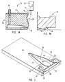
- FIG.1A a schematic side view of an ink jet printhead of the type employed with the present invention is shown in Fig.1A, and a cross sectional view of the catcher vacuum port is shown in Fig. 1B.
- the printhead generally designated 10, includes a resonator assembly 12 having an ink manifold and orifice plate (not shown) for generating filaments of ink 14.
- the resonator stimulates the filaments to break off into droplets in the region of charging electrodes 16 on a catcher assembly generally designated 18.
- Drops of ink are selectively charged by the charging electrodes and deflected onto a catcher face 20 and into a catcher throat 22. Uncharged drops proceed undeflected to a print medium (not shown). Collected ink is withdrawn through a catcher tube 24 and is recirculated.
- Fig. 2 illustrates a general view of the underside of the catcher of assembly 18, revealing the major geometric features of vacuum port 26.
- the vacuum port 26 comprises catcher face 20, radius 28, and catcher throat 22.
- the face 20 and radius 28 have the same geometry and function as existing vacuum ports, known in the art.
- the catcher face 20 receives selectively charged drops of ink and the catcher radius 28 directs the flow of selectively charged drops of ink from the catcher face into the catcher throat.
- the unprinted drops from the array of ink jets impact on the face 20 of the catcher, creating a film of ink attached to the face. Due to momentum from the impacting drops, the ink film flows toward the radius 28. In accordance with the Coanda effect, i.e., the tendency for flows to attach to walls or to one another, the wall attachment occurring under a variety of conditions, the film remains attached to the catcher even as it flows around the radius and along the surface toward the throat opening.
- the catcher throat 22 accepts the flow of selectively charged drops of ink from the catcher face.
- the catcher is covered by a simple plate (not shown) which forms one wall of the vacuum port.
- the throat 22 comprises a short, narrow gap 34 with a sudden enlargement 36, downstream of the gap, both of which extend across the width of the port 26 of Fig. 2.
- An elliptical island 30 divides the flow into two paths and, along with elliptical sidewalls 32, creates two converging-diverging channels or passages 33.
- Narrow gap 34, sudden enlargement 36, and passages 33 establish the desired flow regime in the catcher and the catcher return line.
- the catcher To avoid agitation of the ink, the catcher must operate in a different flow regime than slug flow. As the airflow is decreased while the liquid flow is maintained, the flow enters into another regime, commonly known as bubble flow. In this regime of two-phase flow, the airflow is in the form of individual separate bubbles which are entrained in the liquid phase and travel at the velocity of the liquid. Thus, bubble flow provides significantly reduced airflow and much less agitation than slug flow.
- the catcher vacuum port is designed to establish this bubble flow regime in the catcher return line, and at the same time allow the printhead to operate at any orientation without dribbling ink.
- the narrow gap 34 followed by a sudden enlargement 36 and the two converging-diverging channels 33 allow this operation.
- the throat 22 comprises a 0,254 mm (0,010") gap 34 which is 0,762 mm (0.030") in length in the flow direction.
- the 0,254 mm (0.010") gap is followed by a sudden enlargement 36 to 0,762 mm (0.030").
- capillarity effects cause the ink film to fill the gap and restrict the entry of air.
- bubbles individually form downstream of the gap at the 0,762 mm (0.030") enlargement. These bubbles remain individual as they enter the catcher return tube 24 and establish stable bubble flow through the tube to the fluid system.
- the air flow entering the catcher throat for this mode of operation is 0.2 to 0.7 scfh, in comparison to 3 scfh for existing printheads.
- the island and sidewall geometry control the entry of air at various orientations. At the most difficult orientation, when the printhead is on its side with the flow paths one above the other, an upper flow path will ingest more air than a lower flow path and a lower path will more easily dribble.
- the converging geometry provides a low pressure region in the center of each channel and limits the imbalance of air ingestion between the two paths. The bubble formation point shifts toward the outer wall in the upper path, but still maintains bubble flow.
- the illustrated catcher design allows the printhead to operate at low airflows while also operating at all orientations. Thus, the benefits of low catcher airflow are realized without affecting the versatility of the printer.
- the illustrated embodiment of the present invention is useful in the field of ink jet printing, and has the advantage of providing a droplet catcher apparatus which minimizes airflow required to return ink without dripping or dribbling. It is a further advantage of this embodiment that the catcher device contains a vacuum port which returns unprinted ink to the fluid system with minimum agitation. It is yet another advantage of this embodiment that the vacuum catcher port requires minimum air ingestion to control ink removal at any printhead orientation.
Landscapes
- Ink Jet (AREA)
- Particle Formation And Scattering Control In Inkjet Printers (AREA)
Description
- The present invention relates to drop-catcher devices for continuous ink jet printing apparatus and, more particularly, to improved catcher device constructions for controlling the flow of caught ink.
- In general, continuous ink jet printing apparatus have a printhead manifold to which ink is supplied under pressure so as to issue in streams from a printhead orifice plate that is in liquid communication with the cavity. Periodic perturbations are imposed on the liquid streams, such as vibrations by an electromechanical transducer, to cause the streams to break-up into uniformly sized and shaped droplets.
- A charge plate, comprising an array of addressable electrodes, is located proximate the streams break-off points to induce an electrical charge, selectively, on adjacent droplets, in accord with print information signals. Charged droplets are deflected from their nominal trajectory. For example, in a common, binary, printing mode, charged or non-print droplets are deflected into a catcher device and non-charged droplets proceed to the print medium.
- A variety of catcher devices have been developed as constructions to intercept and recirculate the non-print droplets from such printheads. The catcher devices must take several potential problems into account. First, the catcher device must intercept the non-print ink droplets in a way that avoids splattering them onto the print medium, or scattering into an ink mist, which can also cause defects on the print media. Second, the catcher devices must effectively remove the caught ink away from the droplet interception zone so that a build-up of ink on the catching surface does not block the flight path of printing drops.
- To accomplish these purposes, one current catcher for existing printheads requires nearly 3 scfh of air flow to guarantee that ink does not drip from the printhead when operated at various heights and angles. The two-phase flow regime is that of slug flow in which frothy slugs of ink travel at a much higher rate than the average liquid velocity. As a result, the ink is agitated by the airflow as it travels 3,66-7,32 m (12 to 24 feet) back to the fluid system and, as a result, is subject to evaporation and atomization. Such airflow can cause or contribute to several problems.
- One, the present catcher design requires a screen to regulate the high air flow into the catcher. Placement and contour of the screen is critical to proper printhead function. Second, high evaporation rates require a replenishment system with a specifically designed fluid to replace evaporated ink components. Third, high and variable (machine-to-machine, environment-to-environment, etc.) evaporation rates affect ink concentration control using the drop counting method. Additionally, aeration of the ink may be related to mist generation in the fluid system, requiring a replaceable filter media to protect vacuum system components from ingested mist. For some inks aeration of the ink results in a little-understood aging process in which critical runnability properties of the ink degrade. Furthermore, for some inks, aeration of the ink results in foam generation, which adversely affects the function of the fluid system and/or printhead. Also, high catcher airflow may ingest paper fibers and debris which may interface with print drops, thus causing print defects. Finally, high catcher airflow, especially together with a misshapen screen, may deflect print drops, thus causing print defects.
- One approach to improve catcher construction is to provide a catcher having a screen disposed in the catcher throat for wicking ink into the catcher throat. However, a catcher assembly with a screen in the catcher throat is difficult to fabricate. The regulation of ink flow and airflow into the catcher throat is sensitive to the position and shape of the screen.
- Low catcher airflow is desirable in view of the problems listed above. The difficulty with low air flow to this point has been that the ink is not contained in the printhead if it is operated at low airflow, especially when operated at certain orientations relative to gravity.
- It is seen then that there is a need for a low airflow catcher device which overcomes the problems associated with the prior art.
- US-A-3836914 discloses a drop catcher apparatus for a continuous ink jet printer which generates a row of parallel selectively charged drop streams from a fluid system. The drop catcher apparatus comprises a catcher vacuum port for establishing reduced air flow and returning the selectively charged drops of ink from the printhead to the fluid system. The drop catcher apparatus further comprises a catcher face for receiving selectively charged drops of ink, a catcher radius associated with the catcher face for directing the flow of respectively charged drops of ink from the catcher face and a catcher throat associated with the catcher radius for accepting a flow of selectively charged drops of ink from the catcher radius. Attention is also drawn to EP-A-0561205, US-A-4268664 and US-A-4829664.
- Accordingly, it is an object of the present invention to provide for continuous ink jet printing, a droplet catcher apparatus containing a vacuum port which minimizes airflow required to return ink without dripping or dribbling. It is a further object of the present invention to provide such a catcher device which contains a vacuum port for the return of unprinted ink to the fluid system for reuse with minimum agitation. The droplet catcher apparatus is desirably simple in structure.
- According to the present invention, there is provided a drop catcher apparatus for a continuous ink jet printer which generates a row of parallel selectively charged drop streams from a fluid system, the drop catcher apparatus comprising a catcher vacuum port for establishing reduced airflow and returning the selectively charged drops of ink from the printhead to the fluid system and comprising:
- a catcher face for receiving selectively charged drops of ink;
- a catcher radius associated with the catcher face for directing the flow of selectively charged drops of ink from the catcher face; and
- a catcher throat associated with the catcher radius for accepting a flow of selectively charged drops of ink from the catcher radius, characterised in that the catcher throat has short, narrow gap with a sudden enlargement downstream of the gap followed by a gap of constant width downstream of the sudden enlargement and in that the catcher throat further comprises two converging-diverging channels formed by an elliptical island and elliptical sidewalls.
-
- The catcher design of the present invention eliminates the need for a screen to regulate the mixing of air and ink in the catcher throat. In addition, the new catcher design allows the printhead to operate at low airflows while also operating at all orientations. Thus, the benefits of low catcher airflow are realized without affecting the versatility of the printer.
- An embodiment of the invention will now be described with reference to the accompanying drawings.
-
- Fig. 1A is a schematic side view of an ink jet printhead useful with a catcher according to the present invention;
- Fig. 1B is a cross sectional view of a catcher vacuum port in accordance with the present invention; and
- Fig. 2 illustrates the underside of the catcher, revealing major geometric features of a vacuum port design, embodying the present invention.
-
- Referring to the drawings, a schematic side view of an ink jet printhead of the type employed with the present invention is shown in Fig.1A, and a cross sectional view of the catcher vacuum port is shown in Fig. 1B. The printhead, generally designated 10, includes a
resonator assembly 12 having an ink manifold and orifice plate (not shown) for generating filaments ofink 14. The resonator stimulates the filaments to break off into droplets in the region ofcharging electrodes 16 on a catcher assembly generally designated 18. Drops of ink are selectively charged by the charging electrodes and deflected onto acatcher face 20 and into acatcher throat 22. Uncharged drops proceed undeflected to a print medium (not shown). Collected ink is withdrawn through acatcher tube 24 and is recirculated. - The purpose of the present invention is to provide a catcher vacuum port which is simple in structure, which returns unprinted ink to the fluid system with minimum agitation, and which requires minimum air ingestion to control ink removal at any printhead orientation. Fig. 2 illustrates a general view of the underside of the catcher of
assembly 18, revealing the major geometric features ofvacuum port 26. Thevacuum port 26 comprisescatcher face 20,radius 28, andcatcher throat 22. Theface 20 andradius 28 have the same geometry and function as existing vacuum ports, known in the art. Thecatcher face 20 receives selectively charged drops of ink and thecatcher radius 28 directs the flow of selectively charged drops of ink from the catcher face into the catcher throat. The unprinted drops from the array of ink jets impact on theface 20 of the catcher, creating a film of ink attached to the face. Due to momentum from the impacting drops, the ink film flows toward theradius 28. In accordance with the Coanda effect, i.e., the tendency for flows to attach to walls or to one another, the wall attachment occurring under a variety of conditions, the film remains attached to the catcher even as it flows around the radius and along the surface toward the throat opening. Thecatcher throat 22 accepts the flow of selectively charged drops of ink from the catcher face. The catcher is covered by a simple plate (not shown) which forms one wall of the vacuum port. - As illustrated in Fig. 1B, the
throat 22 comprises a short,narrow gap 34 with asudden enlargement 36, downstream of the gap, both of which extend across the width of theport 26 of Fig. 2. Anelliptical island 30 divides the flow into two paths and, along withelliptical sidewalls 32, creates two converging-diverging channels orpassages 33.Narrow gap 34,sudden enlargement 36, andpassages 33 establish the desired flow regime in the catcher and the catcher return line. - To avoid agitation of the ink, the catcher must operate in a different flow regime than slug flow. As the airflow is decreased while the liquid flow is maintained, the flow enters into another regime, commonly known as bubble flow. In this regime of two-phase flow, the airflow is in the form of individual separate bubbles which are entrained in the liquid phase and travel at the velocity of the liquid. Thus, bubble flow provides significantly reduced airflow and much less agitation than slug flow. The catcher vacuum port is designed to establish this bubble flow regime in the catcher return line, and at the same time allow the printhead to operate at any orientation without dribbling ink. The
narrow gap 34 followed by asudden enlargement 36 and the two converging-divergingchannels 33 allow this operation. - In a preferred embodiment of the present invention, the
throat 22 comprises a 0,254 mm (0,010")gap 34 which is 0,762 mm (0.030") in length in the flow direction. The 0,254 mm (0.010") gap is followed by asudden enlargement 36 to 0,762 mm (0.030"). As the ink film enters thethroat 22, capillarity effects cause the ink film to fill the gap and restrict the entry of air. At the center of each branch of flow around theisland 30, bubbles individually form downstream of the gap at the 0,762 mm (0.030") enlargement. These bubbles remain individual as they enter thecatcher return tube 24 and establish stable bubble flow through the tube to the fluid system. The air flow entering the catcher throat for this mode of operation is 0.2 to 0.7 scfh, in comparison to 3 scfh for existing printheads. - The island and sidewall geometry control the entry of air at various orientations. At the most difficult orientation, when the printhead is on its side with the flow paths one above the other, an upper flow path will ingest more air than a lower flow path and a lower path will more easily dribble. The converging geometry provides a low pressure region in the center of each channel and limits the imbalance of air ingestion between the two paths. The bubble formation point shifts toward the outer wall in the upper path, but still maintains bubble flow. The illustrated catcher design allows the printhead to operate at low airflows while also operating at all orientations. Thus, the benefits of low catcher airflow are realized without affecting the versatility of the printer.
- The illustrated embodiment of the present invention is useful in the field of ink jet printing, and has the advantage of providing a droplet catcher apparatus which minimizes airflow required to return ink without dripping or dribbling. It is a further advantage of this embodiment that the catcher device contains a vacuum port which returns unprinted ink to the fluid system with minimum agitation. It is yet another advantage of this embodiment that the vacuum catcher port requires minimum air ingestion to control ink removal at any printhead orientation.
Claims (7)
- A drop catcher apparatus for a continuous ink jet printer which generates a row of parallel selectively charged drop streams from a fluid system, the drop catcher apparatus comprising a catcher vacuum port for establishing reduced airflow and returning the selectively charged drops of ink from the printhead to the fluid system and comprising:a catcher face (20) for receiving selectively charged drops of ink;a catcher radius (28) associated with the catcher face (20) for directing the flow of selectively charged drops of ink from the catcher face; anda catcher throat (22) associated with the catcher radius for accepting a flow of selectively charged drops of ink from the catcher radius (28), wherein the catcher throat (22) has short, narrow gap (34) with a sudden enlargement (36) downstream of the gap followed by a gap of constant width downstream of the sudden enlargement and the catcher throat (22) further comprises two converging-diverging channels (33) formed by an elliptical island (30) and elliptical sidewalls (32).
- A drop catcher apparatus as claimed in claim 1, characterised in that the short, narrow gap (34) of the catcher throat (22) comprises a gap of approximately 0,254 mm (0.010 inch).
- A drop catcher apparatus as claimed in claim 1 or claim 2, characterised in that the short, narrow gap (34) of the catcher throat (22) comprises a gap approximately 0,762 mm (0.030 inch) in length.
- A drop catcher apparatus as claimed in any of claims 1 to 3, characterised in that the sudden enlargement of the catcher throat (22) downstream of the gap (34) comprises a sudden enlargement of approximately 0,762 mm (0.030 inch).
- A drop catcher apparatus as claimed in claim 4, characterised in that a balance of ingested airflow between the two converging-diverging channels (33) is maintained by converging-diverging geometry of the channels (33).
- A drop catcher apparatus as claimed in claim 1 further comprising capillarity effects as the flow of selectively charged drops of ink enters the catcher throat (22), causing ink film to fill the gap (34) and restrict entry of air.
- A drop catcher apparatus as claimed in claim 1, characterised in that bubbles individually form downstream of the gap (34) at the enlargement (36).
Applications Claiming Priority (2)
| Application Number | Priority Date | Filing Date | Title |
|---|---|---|---|
| US64023796A | 1996-04-30 | 1996-04-30 | |
| US640237 | 1996-04-30 |
Publications (2)
| Publication Number | Publication Date |
|---|---|
| EP0805039A1 EP0805039A1 (en) | 1997-11-05 |
| EP0805039B1 true EP0805039B1 (en) | 2001-12-12 |
Family
ID=24567408
Family Applications (1)
| Application Number | Title | Priority Date | Filing Date |
|---|---|---|---|
| EP19970302696 Expired - Lifetime EP0805039B1 (en) | 1996-04-30 | 1997-04-21 | Low airflow catcher for continuous ink jet printers |
Country Status (5)
| Country | Link |
|---|---|
| EP (1) | EP0805039B1 (en) |
| JP (1) | JPH1044404A (en) |
| AU (1) | AU734900C (en) |
| CA (1) | CA2203957A1 (en) |
| DE (1) | DE69708963T2 (en) |
Families Citing this family (3)
| Publication number | Priority date | Publication date | Assignee | Title |
|---|---|---|---|---|
| US6962411B2 (en) * | 2003-01-02 | 2005-11-08 | Eastman Kodak Company | Anti-wicking catcher arrangement for a solvent ink printhead |
| US6926394B2 (en) | 2003-03-13 | 2005-08-09 | Eastman Kodak Company | Elastomeric polymer catcher for continuous ink jet printers |
| US9505220B1 (en) | 2015-06-11 | 2016-11-29 | Eastman Kodak Company | Catcher for collecting ink from non-printed drops |
Family Cites Families (5)
| Publication number | Priority date | Publication date | Assignee | Title |
|---|---|---|---|---|
| US3836914A (en) * | 1972-12-20 | 1974-09-17 | Mead Corp | Catcher for a jet drop recorder |
| US4268836A (en) * | 1979-10-25 | 1981-05-19 | The Mead Corporation | Ink jet printer having improved catcher |
| US4839644A (en) * | 1987-06-10 | 1989-06-13 | Schlumberger Technology Corp. | System and method for communicating signals in a cased borehole having tubing |
| US4839664A (en) * | 1987-07-02 | 1989-06-13 | Burlington Industries, Inc. | Fluid-jet catcher with removable porous metal ingestion blade |
| US5469202A (en) * | 1992-03-20 | 1995-11-21 | Scitex Digital Printing, Inc. | Continuous ink jet catcher with improved screen structure |
-
1997
- 1997-04-21 DE DE1997608963 patent/DE69708963T2/en not_active Expired - Lifetime
- 1997-04-21 EP EP19970302696 patent/EP0805039B1/en not_active Expired - Lifetime
- 1997-04-28 JP JP11104697A patent/JPH1044404A/en active Pending
- 1997-04-29 CA CA 2203957 patent/CA2203957A1/en not_active Abandoned
- 1997-04-30 AU AU19931/97A patent/AU734900C/en not_active Ceased
Also Published As
| Publication number | Publication date |
|---|---|
| DE69708963T2 (en) | 2002-06-06 |
| EP0805039A1 (en) | 1997-11-05 |
| JPH1044404A (en) | 1998-02-17 |
| AU734900C (en) | 2002-04-18 |
| DE69708963D1 (en) | 2002-01-24 |
| CA2203957A1 (en) | 1997-10-30 |
| AU734900B2 (en) | 2001-06-28 |
| AU1993197A (en) | 1997-11-06 |
Similar Documents
| Publication | Publication Date | Title |
|---|---|---|
| JP4109912B2 (en) | Inkjet printer | |
| US6863385B2 (en) | Continuous ink-jet printing method and apparatus | |
| EP2142372B1 (en) | Printer having improved gas flow drop deflection | |
| CA1143781A (en) | Air flow tunnel for reducing ink jet drag on array head | |
| CN101641217A (en) | Wide format print head with air injector | |
| US8091983B2 (en) | Jet directionality control using printhead nozzle | |
| US6234620B1 (en) | Continuous ink jet printer catcher and method for making same | |
| US7070266B2 (en) | Ink jet recording head cartridge | |
| EP0805039B1 (en) | Low airflow catcher for continuous ink jet printers | |
| CN110770030B (en) | charging electrode | |
| EP0805040B1 (en) | Bubble flow detection | |
| US8091992B2 (en) | Deflection device including gas flow restriction device | |
| EP0378323B1 (en) | Variable orientation ink catcher | |
| US20100277552A1 (en) | Jet directionality control using printhead delivery channel | |
| US9505220B1 (en) | Catcher for collecting ink from non-printed drops | |
| JP2021062487A (en) | Inkjet recording device | |
| US20100277522A1 (en) | Printhead configuration to control jet directionality | |
| US8857954B2 (en) | Printhead including coanda catcher with grooved radius | |
| US8740323B2 (en) | Viscosity modulated dual feed continuous liquid ejector | |
| US8091990B2 (en) | Continuous printhead contoured gas flow device | |
| US8777387B1 (en) | Printhead including coanda catcher with grooved radius | |
| US8746863B1 (en) | Printhead including coanda catcher with grooved radius | |
| US8740366B1 (en) | Printhead including coanda catcher with grooved radius | |
| JPH0199851A (en) | Ink jet recorder | |
| JPH11198415A (en) | Method and apparatus for forming image, and ink discharge head |
Legal Events
| Date | Code | Title | Description |
|---|---|---|---|
| PUAI | Public reference made under article 153(3) epc to a published international application that has entered the european phase |
Free format text: ORIGINAL CODE: 0009012 |
|
| AK | Designated contracting states |
Kind code of ref document: A1 Designated state(s): DE FR GB |
|
| 17P | Request for examination filed |
Effective date: 19980212 |
|
| 17Q | First examination report despatched |
Effective date: 19981223 |
|
| GRAG | Despatch of communication of intention to grant |
Free format text: ORIGINAL CODE: EPIDOS AGRA |
|
| GRAG | Despatch of communication of intention to grant |
Free format text: ORIGINAL CODE: EPIDOS AGRA |
|
| GRAH | Despatch of communication of intention to grant a patent |
Free format text: ORIGINAL CODE: EPIDOS IGRA |
|
| GRAH | Despatch of communication of intention to grant a patent |
Free format text: ORIGINAL CODE: EPIDOS IGRA |
|
| GRAA | (expected) grant |
Free format text: ORIGINAL CODE: 0009210 |
|
| AK | Designated contracting states |
Kind code of ref document: B1 Designated state(s): DE FR GB |
|
| REG | Reference to a national code |
Ref country code: GB Ref legal event code: IF02 |
|
| REF | Corresponds to: |
Ref document number: 69708963 Country of ref document: DE Date of ref document: 20020124 |
|
| ET | Fr: translation filed | ||
| PLBE | No opposition filed within time limit |
Free format text: ORIGINAL CODE: 0009261 |
|
| STAA | Information on the status of an ep patent application or granted ep patent |
Free format text: STATUS: NO OPPOSITION FILED WITHIN TIME LIMIT |
|
| 26N | No opposition filed | ||
| REG | Reference to a national code |
Ref country code: GB Ref legal event code: 732E |
|
| REG | Reference to a national code |
Ref country code: FR Ref legal event code: TP |
|
| PGFP | Annual fee paid to national office [announced via postgrant information from national office to epo] |
Ref country code: GB Payment date: 20050314 Year of fee payment: 9 |
|
| PGFP | Annual fee paid to national office [announced via postgrant information from national office to epo] |
Ref country code: FR Payment date: 20050401 Year of fee payment: 9 |
|
| PGFP | Annual fee paid to national office [announced via postgrant information from national office to epo] |
Ref country code: DE Payment date: 20050429 Year of fee payment: 9 |
|
| PG25 | Lapsed in a contracting state [announced via postgrant information from national office to epo] |
Ref country code: DE Free format text: LAPSE BECAUSE OF THE APPLICANT RENOUNCES Effective date: 20060221 |
|
| PG25 | Lapsed in a contracting state [announced via postgrant information from national office to epo] |
Ref country code: GB Free format text: LAPSE BECAUSE OF NON-PAYMENT OF DUE FEES Effective date: 20060421 |
|
| GBPC | Gb: european patent ceased through non-payment of renewal fee |
Effective date: 20060421 |
|
| REG | Reference to a national code |
Ref country code: FR Ref legal event code: ST Effective date: 20061230 |
|
| PG25 | Lapsed in a contracting state [announced via postgrant information from national office to epo] |
Ref country code: FR Free format text: LAPSE BECAUSE OF NON-PAYMENT OF DUE FEES Effective date: 20060502 |