EP0805036A2 - Top feed droplet generator - Google Patents
Top feed droplet generator Download PDFInfo
- Publication number
- EP0805036A2 EP0805036A2 EP97302690A EP97302690A EP0805036A2 EP 0805036 A2 EP0805036 A2 EP 0805036A2 EP 97302690 A EP97302690 A EP 97302690A EP 97302690 A EP97302690 A EP 97302690A EP 0805036 A2 EP0805036 A2 EP 0805036A2
- Authority
- EP
- European Patent Office
- Prior art keywords
- fluid
- droplet generator
- resonator body
- generator assembly
- nozzle plate
- Prior art date
- Legal status (The legal status is an assumption and is not a legal conclusion. Google has not performed a legal analysis and makes no representation as to the accuracy of the status listed.)
- Granted
Links
Images
Classifications
-
- B—PERFORMING OPERATIONS; TRANSPORTING
- B41—PRINTING; LINING MACHINES; TYPEWRITERS; STAMPS
- B41J—TYPEWRITERS; SELECTIVE PRINTING MECHANISMS, i.e. MECHANISMS PRINTING OTHERWISE THAN FROM A FORME; CORRECTION OF TYPOGRAPHICAL ERRORS
- B41J2/00—Typewriters or selective printing mechanisms characterised by the printing or marking process for which they are designed
- B41J2/005—Typewriters or selective printing mechanisms characterised by the printing or marking process for which they are designed characterised by bringing liquid or particles selectively into contact with a printing material
- B41J2/01—Ink jet
- B41J2/015—Ink jet characterised by the jet generation process
- B41J2/02—Ink jet characterised by the jet generation process generating a continuous ink jet
- B41J2/03—Ink jet characterised by the jet generation process generating a continuous ink jet by pressure
-
- B—PERFORMING OPERATIONS; TRANSPORTING
- B41—PRINTING; LINING MACHINES; TYPEWRITERS; STAMPS
- B41J—TYPEWRITERS; SELECTIVE PRINTING MECHANISMS, i.e. MECHANISMS PRINTING OTHERWISE THAN FROM A FORME; CORRECTION OF TYPOGRAPHICAL ERRORS
- B41J2/00—Typewriters or selective printing mechanisms characterised by the printing or marking process for which they are designed
- B41J2/005—Typewriters or selective printing mechanisms characterised by the printing or marking process for which they are designed characterised by bringing liquid or particles selectively into contact with a printing material
- B41J2/01—Ink jet
- B41J2/17—Ink jet characterised by ink handling
- B41J2/175—Ink supply systems ; Circuit parts therefor
Definitions
- the present invention relates to continuous ink jet printers and, more particularly, to a droplet generator for a continuous ink jet printer, the drop generator having an integral fluid cavity.
- Ink jet printing systems are known in which a print head defines one or more rows of orifices which receive an electrically conductive recording fluid, such as for instance a water base ink, from a pressurized fluid supply manifold and eject the fluid in rows of parallel streams.
- Printers using such print heads accomplish graphic reproduction by selectively charging and deflecting the drops in each of the streams and depositing at least some of the drops on a print receiving medium, while others of the drops strike a drop catcher device.
- Droplet generators are one of the major components in a continuous ink jet printhead. Droplet generators often uses a nozzle plate attached to a resonant body to stimulate the jets.
- Several different methods are currently in practice to supply fluid to the nozzle plate.
- One known method includes fluid passages originating at the nodal line of the resonant body, with internal cavities leading to the nozzle plate.
- Another known method teaches that the fluid ingress can be achieved by feeding ink toward the same end of the nozzle plate, thus eliminating the longer internal cavities required with a nodal line feed droplet generator. This latter method is referred to as a bottom front feed droplet generator.
- a bottom front feed droplet generator As a variation of that concept, it is known that fluid can be fed from the side, as opposed to the front.
- a second drawback of current methods is that, in some cases, asymmetric modes of vibration may occur very near the desired mode.
- a shear type mode can exist across the narrow dimension of the body, parallel to the nozzle array. The damaging effect can be that each side of nozzle will experience out of phase excitation, thus destroying the desired uniform oscillations.
- These asymmetric modes generally will not occur unless the body is unsymmetrical or it is driven unsymmetrically.
- the front feed design could provide the means to excite the unwanted asymmetric mode.
- the droplet generator utilizes a resonant body configuration that minimizes space requirements for an ink jet printhead.
- a droplet generator for use with an ink jet printhead of a continuous ink jet printer.
- the droplet generator assembly has a nozzle plate with associated nozzles to stimulate jets.
- the droplet generator assembly has a fluid ingress location and a fluid egress location, on a side of the resonator body opposite the nozzle plate.
- a fluid trench redirects flow in-line with the nozzles.
- a fluid passage extends from the fluid ingress location to the fluid trench.
- the droplet generator assembly provides a variety of advantages.
- the droplet generator utilizes a resonant body configuration.
- the droplet generator provides fluid ingress and egress on the side opposite the nozzle plate. This, in turn, provides the advantage of minimizing space requirements for an ink jet printhead.
- the present invention provides a droplet generator for an ink jet printhead.
- the droplet generator according to the present invention has an integral fluid cavity wherein fluid ingress and egress to and from the resonator body is on a second side of the resonator body opposite the nozzle plate which is on a first side of the resonator body, i.e., a top feed resonator.
- a top feed resonator i.e., a top feed resonator.
- the external tubing is required by prior art systems because fluid tubing is typically routed to a point above the drop generator, as opposed to its sides, for space economy reasons.
- the top feed resonator has incorporated prior external fluid tubing into the fluid passages internal to the resonator body. This has the desirable effect of minimizing space requirements for an ink jet printhead.
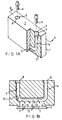
- a droplet generator 1 comprises fluid ingress and egress on a surface 7 opposite nozzle plate 2.
- a counterbore 3 feature permits an effective means to secure fittings 6 to the droplet generator 1.
- a fluid passage 4 allows fluid to travel from an ingress point 8 down to the nozzle plate 2 and fluid trench 5.
- Narrow fluid trench 5 redirects fluid flow from the fluid passage 4 to an in-line direction with the nozzles associated with nozzle plate 2.
- the fluid passage 4 is located substantially along a centerline of the resonator body. Since the fluid passage 4 from the ingress point 8 to fluid trench 5 is not directly above fluid trench 5, this avoids fluid resonances directly between the nozzle plate 2 and the fluid passage 4.
- the fluid passage 4 follows a 'U' shaped path through the resonator, as best illustrated in Fig. 1B.
- the narrow fluid trench 5 intersects the fluid passage 4 perpendicular to the flow. Fluid flow in passage 4 is in the direction of arrows 10; whereas fluid flow in the trench 5 is in the perpendicular direction, as indicated by arrows 11.
- trench 5 redirects fluid flow from the fluid passage 4 in the direction of arrows 10, to a direction 11 in-line with the nozzles, as indicated by arrows 12.
- crossflush mode where fluid enters the resonator at the ingress point 8 follows the entire fluid passage 4, and exits at the egress point 9. In this mode, some fluid may flow into the narrow fluid trench 5 and weep out of the nozzles.
- the second mode is where a valve external to the resonator and downstream from the egress point may be selectively closed and substantially halt fluid flow from the egress point 9. In this mode, the nozzle plate is the only other passage for fluid to flow and have a much greater resistance to flow than the egress point. Also, greater fluid pressure is established within the resonator and jets are established through the nozzles.
- the droplet generator assembly according to the present invention is useful in continuous ink jet printers.
- the droplet generator utilizes a resonant body configuration.
- the droplet generator provides fluid ingress and egress on the side opposite the nozzle plate. This, in turn, provides the advantage of minimizing space requirements for an ink jet printhead.
Landscapes
- Particle Formation And Scattering Control In Inkjet Printers (AREA)
- Ink Jet (AREA)
Abstract
Description
- The present invention relates to continuous ink jet printers and, more particularly, to a droplet generator for a continuous ink jet printer, the drop generator having an integral fluid cavity.
- Ink jet printing systems are known in which a print head defines one or more rows of orifices which receive an electrically conductive recording fluid, such as for instance a water base ink, from a pressurized fluid supply manifold and eject the fluid in rows of parallel streams. Printers using such print heads accomplish graphic reproduction by selectively charging and deflecting the drops in each of the streams and depositing at least some of the drops on a print receiving medium, while others of the drops strike a drop catcher device.
- Droplet generators are one of the major components in a continuous ink jet printhead. Droplet generators often uses a nozzle plate attached to a resonant body to stimulate the jets. Several different methods are currently in practice to supply fluid to the nozzle plate. One known method includes fluid passages originating at the nodal line of the resonant body, with internal cavities leading to the nozzle plate. Another known method teaches that the fluid ingress can be achieved by feeding ink toward the same end of the nozzle plate, thus eliminating the longer internal cavities required with a nodal line feed droplet generator. This latter method is referred to as a bottom front feed droplet generator. As a variation of that concept, it is known that fluid can be fed from the side, as opposed to the front.
- In all cases, additional space is required to provide a means to get the fluid to those inlet and outlet points. In the case of the side feed, this is especially undesirable because this increases the amount of space required perpendicular to the typical flow of the print media relative to a jet array printhead. A second drawback of current methods is that, in some cases, asymmetric modes of vibration may occur very near the desired mode. In particular, a shear type mode can exist across the narrow dimension of the body, parallel to the nozzle array. The damaging effect can be that each side of nozzle will experience out of phase excitation, thus destroying the desired uniform oscillations. These asymmetric modes generally will not occur unless the body is unsymmetrical or it is driven unsymmetrically. In particular, the front feed design could provide the means to excite the unwanted asymmetric mode.
- It is seen then that there is a need for a droplet generator and the associated fluid cavity which reduces the space requirement while overcoming the problems associated with prior art drop generator designs.
- This need is met by the droplet generator according to the present invention, wherein the droplet generator utilizes a resonant body configuration that minimizes space requirements for an ink jet printhead.
- In accordance with one aspect of the present invention, a droplet generator is provided for use with an ink jet printhead of a continuous ink jet printer. The droplet generator assembly has a nozzle plate with associated nozzles to stimulate jets. The droplet generator assembly has a fluid ingress location and a fluid egress location, on a side of the resonator body opposite the nozzle plate. A fluid trench redirects flow in-line with the nozzles. A fluid passage extends from the fluid ingress location to the fluid trench.
- The droplet generator assembly according to the present invention provides a variety of advantages. First, the droplet generator utilizes a resonant body configuration. In addition, the droplet generator provides fluid ingress and egress on the side opposite the nozzle plate. This, in turn, provides the advantage of minimizing space requirements for an ink jet printhead.
- Other objects and advantages of the invention will be apparent from the following description, the accompanying drawings and the appended claims.
-
- Fig. 1A is an exploded view of the components of the droplet generator assembly of the present invention; and
- Fig. 1B is a view along line B-B of Fig. 1A.
- The present invention provides a droplet generator for an ink jet printhead. The droplet generator according to the present invention has an integral fluid cavity wherein fluid ingress and egress to and from the resonator body is on a second side of the resonator body opposite the nozzle plate which is on a first side of the resonator body, i.e., a top feed resonator. Of course, with ink jet printing systems, the goal is to get fluid into the resonator body and down to the nozzle plate. Existing top and front feed resonators do this very efficiently, but require external fluid tubing to the ingress and egress points. The external tubing is required by prior art systems because fluid tubing is typically routed to a point above the drop generator, as opposed to its sides, for space economy reasons. In accordance with the present invention, the top feed resonator has incorporated prior external fluid tubing into the fluid passages internal to the resonator body. This has the desirable effect of minimizing space requirements for an ink jet printhead.
- Referring now to the drawings, in Figs. 1A and 1B there are illustrated the components of the droplet generator assembly according to the present invention. A droplet generator 1 comprises fluid ingress and egress on a
surface 7opposite nozzle plate 2. A counterbore 3 feature permits an effective means to secure fittings 6 to the droplet generator 1. A fluid passage 4 allows fluid to travel from an ingress point 8 down to thenozzle plate 2 andfluid trench 5. Narrow fluid trench 5 redirects fluid flow from the fluid passage 4 to an in-line direction with the nozzles associated withnozzle plate 2. The fluid passage 4 is located substantially along a centerline of the resonator body. Since the fluid passage 4 from the ingress point 8 tofluid trench 5 is not directly abovefluid trench 5, this avoids fluid resonances directly between thenozzle plate 2 and the fluid passage 4. - The fluid passage 4 follows a 'U' shaped path through the resonator, as best illustrated in Fig. 1B. The
narrow fluid trench 5 intersects the fluid passage 4 perpendicular to the flow. Fluid flow in passage 4 is in the direction ofarrows 10; whereas fluid flow in thetrench 5 is in the perpendicular direction, as indicated byarrows 11. Hence,trench 5 redirects fluid flow from the fluid passage 4 in the direction ofarrows 10, to adirection 11 in-line with the nozzles, as indicated byarrows 12. - There are two modes of operation which can allow two different egress points. The first is what is referred to as crossflush mode, where fluid enters the resonator at the ingress point 8, follows the entire fluid passage 4, and exits at the
egress point 9. In this mode, some fluid may flow into thenarrow fluid trench 5 and weep out of the nozzles. The second mode is where a valve external to the resonator and downstream from the egress point may be selectively closed and substantially halt fluid flow from theegress point 9. In this mode, the nozzle plate is the only other passage for fluid to flow and have a much greater resistance to flow than the egress point. Also, greater fluid pressure is established within the resonator and jets are established through the nozzles. - The droplet generator assembly according to the present invention is useful in continuous ink jet printers. The droplet generator utilizes a resonant body configuration. In addition, the droplet generator provides fluid ingress and egress on the side opposite the nozzle plate. This, in turn, provides the advantage of minimizing space requirements for an ink jet printhead.
- Having described the invention in detail and by reference to the preferred embodiment thereof, it will be apparent that other modifications and variations are possible without departing from the scope of the invention defined in the appended claims.
Claims (5)
- A droplet generator assembly for an ink jet printhead of a continuous ink jet printer, the droplet generator assembly having a resonator body, the assembly comprising:a nozzle plate on a first side of the resonator body, the nozzle plate having associated nozzles to stimulate jets;a fluid ingress location on a second side of the resonator body, opposite the first side of the resonator body;a fluid egress location;a fluid passage extending from the fluid ingress location to the fluid egress location;a fluid trench to redirect flow from the fluid passage to a direction in-line with the nozzles.
- A droplet generator assembly as claimed in claim 1 wherein the fluid passage from the ingress point to the fluid trench is not located directly above the fluid trench.
- A droplet generator assembly as claimed in claim 1 wherein the fluid passage comprises a U-shaped fluid passage.
- A droplet generator assembly as claimed in claim 1 wherein the fluid egress location comprises a location on a second side of the resonator body, opposite the first side of the resonator body.
- A droplet generator assembly as claimed in claim 1 wherein the fluid passage is located substantially along a centerline of the resonator body.
Applications Claiming Priority (2)
| Application Number | Priority Date | Filing Date | Title |
|---|---|---|---|
| US64018096A | 1996-04-30 | 1996-04-30 | |
| US640180 | 1996-04-30 |
Publications (3)
| Publication Number | Publication Date |
|---|---|
| EP0805036A2 true EP0805036A2 (en) | 1997-11-05 |
| EP0805036A3 EP0805036A3 (en) | 1998-05-06 |
| EP0805036B1 EP0805036B1 (en) | 2001-09-19 |
Family
ID=24567172
Family Applications (1)
| Application Number | Title | Priority Date | Filing Date |
|---|---|---|---|
| EP19970302690 Expired - Lifetime EP0805036B1 (en) | 1996-04-30 | 1997-04-21 | Top feed droplet generator |
Country Status (5)
| Country | Link |
|---|---|
| EP (1) | EP0805036B1 (en) |
| JP (1) | JPH1034936A (en) |
| AU (1) | AU714251B2 (en) |
| CA (1) | CA2203951A1 (en) |
| DE (1) | DE69706751T2 (en) |
Cited By (5)
| Publication number | Priority date | Publication date | Assignee | Title |
|---|---|---|---|---|
| US6382782B1 (en) * | 2000-12-29 | 2002-05-07 | Eastman Kodak Company | CMOS/MEMS integrated ink jet print head with oxide based lateral flow nozzle architecture and method of forming same |
| US6497510B1 (en) * | 1999-12-22 | 2002-12-24 | Eastman Kodak Company | Deflection enhancement for continuous ink jet printers |
| US6502925B2 (en) | 2001-02-22 | 2003-01-07 | Eastman Kodak Company | CMOS/MEMS integrated ink jet print head and method of operating same |
| US6986566B2 (en) | 1999-12-22 | 2006-01-17 | Eastman Kodak Company | Liquid emission device |
| EP2236298A1 (en) * | 2005-09-07 | 2010-10-06 | Eastman Kodak Company | Fluid ejector with anisotropically etched fluid chambers |
Family Cites Families (7)
| Publication number | Priority date | Publication date | Assignee | Title |
|---|---|---|---|---|
| JPS5830830B2 (en) * | 1979-02-23 | 1983-07-01 | 株式会社リコー | Multi-nozzle head for inkjet |
| GB8622196D0 (en) * | 1986-09-15 | 1986-10-22 | Domino Printing Sciences Plc | Ink jet marking apparatus |
| US4746929A (en) * | 1987-01-16 | 1988-05-24 | Xerox Corporation | Traveling wave droplet generator for an ink jet printer |
| US4827287A (en) * | 1988-08-08 | 1989-05-02 | Eastman Kodak Company | Continuous ink jet printer having improved stimulation waveguide construction |
| US4937589A (en) * | 1989-08-23 | 1990-06-26 | Eastman Kodak Company | Continuous ink jet print heads |
| US4999647A (en) * | 1989-12-28 | 1991-03-12 | Eastman Kodak Company | Synchronous stimulation for long array continuous ink jet printer |
| EP0624469B1 (en) * | 1993-05-12 | 1998-06-10 | SCITEX DIGITAL PRINTING, Inc. | Improved drop generator utilizing damping for mode suppression |
-
1997
- 1997-04-21 EP EP19970302690 patent/EP0805036B1/en not_active Expired - Lifetime
- 1997-04-21 DE DE1997606751 patent/DE69706751T2/en not_active Expired - Lifetime
- 1997-04-28 JP JP11105297A patent/JPH1034936A/en active Pending
- 1997-04-29 CA CA 2203951 patent/CA2203951A1/en not_active Abandoned
- 1997-04-30 AU AU19935/97A patent/AU714251B2/en not_active Ceased
Cited By (7)
| Publication number | Priority date | Publication date | Assignee | Title |
|---|---|---|---|---|
| US6497510B1 (en) * | 1999-12-22 | 2002-12-24 | Eastman Kodak Company | Deflection enhancement for continuous ink jet printers |
| US6761437B2 (en) | 1999-12-22 | 2004-07-13 | Eastman Kodak Company | Apparatus and method of enhancing fluid deflection in a continuous ink jet printhead |
| US6986566B2 (en) | 1999-12-22 | 2006-01-17 | Eastman Kodak Company | Liquid emission device |
| US6382782B1 (en) * | 2000-12-29 | 2002-05-07 | Eastman Kodak Company | CMOS/MEMS integrated ink jet print head with oxide based lateral flow nozzle architecture and method of forming same |
| US6780339B2 (en) | 2000-12-29 | 2004-08-24 | Eastman Kodak Company | CMOS/MEMS integrated ink jet print head with oxide based lateral flow nozzle architecture and method of forming same |
| US6502925B2 (en) | 2001-02-22 | 2003-01-07 | Eastman Kodak Company | CMOS/MEMS integrated ink jet print head and method of operating same |
| EP2236298A1 (en) * | 2005-09-07 | 2010-10-06 | Eastman Kodak Company | Fluid ejector with anisotropically etched fluid chambers |
Also Published As
| Publication number | Publication date |
|---|---|
| AU1993597A (en) | 1997-11-06 |
| AU714251B2 (en) | 1999-12-23 |
| DE69706751T2 (en) | 2002-07-04 |
| EP0805036B1 (en) | 2001-09-19 |
| EP0805036A3 (en) | 1998-05-06 |
| CA2203951A1 (en) | 1997-10-30 |
| JPH1034936A (en) | 1998-02-10 |
| DE69706751D1 (en) | 2001-10-25 |
Similar Documents
| Publication | Publication Date | Title |
|---|---|---|
| US4364066A (en) | Ink jet printing head | |
| US6409318B1 (en) | Firing chamber configuration in fluid ejection devices | |
| JPH0684071B2 (en) | Printer head for ink jet printer | |
| US6113223A (en) | Ink jet recording head with ink chamber having slanted surfaces to aid bubble removal | |
| CA1126085A (en) | Ink jet print head | |
| US20030016256A1 (en) | Droplet deposition method and apparatus | |
| US6439692B1 (en) | Ink jet recording apparatus and driving method thereof using a flow resistance element to promote collapse of a generated bubble | |
| US5394181A (en) | Air bubble removal in a drop on demand ink jet print head | |
| EP0805036B1 (en) | Top feed droplet generator | |
| CN101218101B (en) | Droplet deposition method and apparatus | |
| JP2005081597A (en) | Inkjet head | |
| JP2607274B2 (en) | Inkjet recording head | |
| KR19990072572A (en) | Lipuid ejecting method and liquid ejecting head | |
| EP0439593A1 (en) | Continuous ink jet print heads. | |
| JPH04212864A (en) | Ink jet recording device | |
| US20040179069A1 (en) | Liquid emission device | |
| EP0461938B1 (en) | Ink jet recording method and ink jet recording apparatus using same | |
| JP3284431B2 (en) | Ink jet recording device | |
| US6254224B1 (en) | Ink jet printer | |
| JP5047958B2 (en) | Droplet deposition method and apparatus | |
| EP1403061B1 (en) | A system and method for uniformly and equally supplying ink to both ends of a droplet generator | |
| JPH05338206A (en) | Ink-jet recording device | |
| JP2801424B2 (en) | Ink jet recording apparatus and ejection recovery method in the apparatus | |
| JP2002321361A (en) | Inkjet recording head | |
| EP0805026B1 (en) | Brazing process for a continuous ink jet printhead |
Legal Events
| Date | Code | Title | Description |
|---|---|---|---|
| PUAI | Public reference made under article 153(3) epc to a published international application that has entered the european phase |
Free format text: ORIGINAL CODE: 0009012 |
|
| AK | Designated contracting states |
Kind code of ref document: A2 Designated state(s): DE FR GB |
|
| PUAL | Search report despatched |
Free format text: ORIGINAL CODE: 0009013 |
|
| RHK1 | Main classification (correction) |
Ipc: B41J 2/14 |
|
| AK | Designated contracting states |
Kind code of ref document: A3 Designated state(s): DE FR GB |
|
| 17P | Request for examination filed |
Effective date: 19980807 |
|
| 17Q | First examination report despatched |
Effective date: 19990720 |
|
| GRAG | Despatch of communication of intention to grant |
Free format text: ORIGINAL CODE: EPIDOS AGRA |
|
| GRAG | Despatch of communication of intention to grant |
Free format text: ORIGINAL CODE: EPIDOS AGRA |
|
| GRAH | Despatch of communication of intention to grant a patent |
Free format text: ORIGINAL CODE: EPIDOS IGRA |
|
| GRAH | Despatch of communication of intention to grant a patent |
Free format text: ORIGINAL CODE: EPIDOS IGRA |
|
| GRAA | (expected) grant |
Free format text: ORIGINAL CODE: 0009210 |
|
| AK | Designated contracting states |
Kind code of ref document: B1 Designated state(s): DE FR GB |
|
| REF | Corresponds to: |
Ref document number: 69706751 Country of ref document: DE Date of ref document: 20011025 |
|
| REG | Reference to a national code |
Ref country code: GB Ref legal event code: IF02 |
|
| ET | Fr: translation filed | ||
| PLBE | No opposition filed within time limit |
Free format text: ORIGINAL CODE: 0009261 |
|
| STAA | Information on the status of an ep patent application or granted ep patent |
Free format text: STATUS: NO OPPOSITION FILED WITHIN TIME LIMIT |
|
| 26N | No opposition filed | ||
| REG | Reference to a national code |
Ref country code: GB Ref legal event code: 732E |
|
| REG | Reference to a national code |
Ref country code: FR Ref legal event code: TP |
|
| PGFP | Annual fee paid to national office [announced via postgrant information from national office to epo] |
Ref country code: GB Payment date: 20120327 Year of fee payment: 16 |
|
| PGFP | Annual fee paid to national office [announced via postgrant information from national office to epo] |
Ref country code: DE Payment date: 20120430 Year of fee payment: 16 |
|
| PGFP | Annual fee paid to national office [announced via postgrant information from national office to epo] |
Ref country code: FR Payment date: 20120503 Year of fee payment: 16 |
|
| GBPC | Gb: european patent ceased through non-payment of renewal fee |
Effective date: 20130421 |
|
| PG25 | Lapsed in a contracting state [announced via postgrant information from national office to epo] |
Ref country code: GB Free format text: LAPSE BECAUSE OF NON-PAYMENT OF DUE FEES Effective date: 20130421 Ref country code: DE Free format text: LAPSE BECAUSE OF NON-PAYMENT OF DUE FEES Effective date: 20131101 |
|
| REG | Reference to a national code |
Ref country code: FR Ref legal event code: ST Effective date: 20131231 |
|
| REG | Reference to a national code |
Ref country code: DE Ref legal event code: R119 Ref document number: 69706751 Country of ref document: DE Effective date: 20131101 |
|
| PG25 | Lapsed in a contracting state [announced via postgrant information from national office to epo] |
Ref country code: FR Free format text: LAPSE BECAUSE OF NON-PAYMENT OF DUE FEES Effective date: 20130430 |