EP0805013B1 - Device for extruding automotive weather strip - Google Patents
Device for extruding automotive weather strip Download PDFInfo
- Publication number
- EP0805013B1 EP0805013B1 EP97302809A EP97302809A EP0805013B1 EP 0805013 B1 EP0805013 B1 EP 0805013B1 EP 97302809 A EP97302809 A EP 97302809A EP 97302809 A EP97302809 A EP 97302809A EP 0805013 B1 EP0805013 B1 EP 0805013B1
- Authority
- EP
- European Patent Office
- Prior art keywords
- extruding
- main
- shaping die
- auxiliary
- extruded
- Prior art date
- Legal status (The legal status is an assumption and is not a legal conclusion. Google has not performed a legal analysis and makes no representation as to the accuracy of the status listed.)
- Expired - Lifetime
Links
- 238000007493 shaping process Methods 0.000 claims description 57
- 239000000463 material Substances 0.000 claims description 47
- 230000015572 biosynthetic process Effects 0.000 claims description 8
- 239000004800 polyvinyl chloride Substances 0.000 claims description 8
- 229920000915 polyvinyl chloride Polymers 0.000 claims description 4
- 239000012530 fluid Substances 0.000 claims 3
- 229920003023 plastic Polymers 0.000 description 9
- 239000004033 plastic Substances 0.000 description 9
- 230000002093 peripheral effect Effects 0.000 description 5
- XLYOFNOQVPJJNP-UHFFFAOYSA-N water Substances O XLYOFNOQVPJJNP-UHFFFAOYSA-N 0.000 description 5
- KAKZBPTYRLMSJV-UHFFFAOYSA-N Butadiene Chemical compound C=CC=C KAKZBPTYRLMSJV-UHFFFAOYSA-N 0.000 description 2
- 229920000459 Nitrile rubber Polymers 0.000 description 2
- 239000004743 Polypropylene Substances 0.000 description 2
- 238000010276 construction Methods 0.000 description 2
- 239000012188 paraffin wax Substances 0.000 description 2
- 229920001155 polypropylene Polymers 0.000 description 2
- 230000003014 reinforcing effect Effects 0.000 description 2
- 239000000853 adhesive Substances 0.000 description 1
- 230000001070 adhesive effect Effects 0.000 description 1
- NTXGQCSETZTARF-UHFFFAOYSA-N buta-1,3-diene;prop-2-enenitrile Chemical compound C=CC=C.C=CC#N NTXGQCSETZTARF-UHFFFAOYSA-N 0.000 description 1
- 238000004140 cleaning Methods 0.000 description 1
- 229920001971 elastomer Polymers 0.000 description 1
- 238000001125 extrusion Methods 0.000 description 1
- 238000012423 maintenance Methods 0.000 description 1
- 239000002991 molded plastic Substances 0.000 description 1
- -1 polypropylene Polymers 0.000 description 1
Images


Classifications
-
- B—PERFORMING OPERATIONS; TRANSPORTING
- B60—VEHICLES IN GENERAL
- B60J—WINDOWS, WINDSCREENS, NON-FIXED ROOFS, DOORS, OR SIMILAR DEVICES FOR VEHICLES; REMOVABLE EXTERNAL PROTECTIVE COVERINGS SPECIALLY ADAPTED FOR VEHICLES
- B60J10/00—Sealing arrangements
- B60J10/70—Sealing arrangements specially adapted for windows or windscreens
-
- B—PERFORMING OPERATIONS; TRANSPORTING
- B29—WORKING OF PLASTICS; WORKING OF SUBSTANCES IN A PLASTIC STATE IN GENERAL
- B29C—SHAPING OR JOINING OF PLASTICS; SHAPING OF MATERIAL IN A PLASTIC STATE, NOT OTHERWISE PROVIDED FOR; AFTER-TREATMENT OF THE SHAPED PRODUCTS, e.g. REPAIRING
- B29C48/00—Extrusion moulding, i.e. expressing the moulding material through a die or nozzle which imparts the desired form; Apparatus therefor
- B29C48/03—Extrusion moulding, i.e. expressing the moulding material through a die or nozzle which imparts the desired form; Apparatus therefor characterised by the shape of the extruded material at extrusion
- B29C48/12—Articles with an irregular circumference when viewed in cross-section, e.g. window profiles
-
- B—PERFORMING OPERATIONS; TRANSPORTING
- B29—WORKING OF PLASTICS; WORKING OF SUBSTANCES IN A PLASTIC STATE IN GENERAL
- B29C—SHAPING OR JOINING OF PLASTICS; SHAPING OF MATERIAL IN A PLASTIC STATE, NOT OTHERWISE PROVIDED FOR; AFTER-TREATMENT OF THE SHAPED PRODUCTS, e.g. REPAIRING
- B29C48/00—Extrusion moulding, i.e. expressing the moulding material through a die or nozzle which imparts the desired form; Apparatus therefor
- B29C48/15—Extrusion moulding, i.e. expressing the moulding material through a die or nozzle which imparts the desired form; Apparatus therefor incorporating preformed parts or layers, e.g. extrusion moulding around inserts
- B29C48/154—Coating solid articles, i.e. non-hollow articles
- B29C48/155—Partial coating thereof
-
- B—PERFORMING OPERATIONS; TRANSPORTING
- B29—WORKING OF PLASTICS; WORKING OF SUBSTANCES IN A PLASTIC STATE IN GENERAL
- B29C—SHAPING OR JOINING OF PLASTICS; SHAPING OF MATERIAL IN A PLASTIC STATE, NOT OTHERWISE PROVIDED FOR; AFTER-TREATMENT OF THE SHAPED PRODUCTS, e.g. REPAIRING
- B29C48/00—Extrusion moulding, i.e. expressing the moulding material through a die or nozzle which imparts the desired form; Apparatus therefor
- B29C48/25—Component parts, details or accessories; Auxiliary operations
- B29C48/30—Extrusion nozzles or dies
- B29C48/304—Extrusion nozzles or dies specially adapted for bringing together components, e.g. melts within the die
-
- B—PERFORMING OPERATIONS; TRANSPORTING
- B60—VEHICLES IN GENERAL
- B60J—WINDOWS, WINDSCREENS, NON-FIXED ROOFS, DOORS, OR SIMILAR DEVICES FOR VEHICLES; REMOVABLE EXTERNAL PROTECTIVE COVERINGS SPECIALLY ADAPTED FOR VEHICLES
- B60J10/00—Sealing arrangements
- B60J10/15—Sealing arrangements characterised by the material
- B60J10/18—Sealing arrangements characterised by the material provided with reinforcements or inserts
-
- B—PERFORMING OPERATIONS; TRANSPORTING
- B60—VEHICLES IN GENERAL
- B60J—WINDOWS, WINDSCREENS, NON-FIXED ROOFS, DOORS, OR SIMILAR DEVICES FOR VEHICLES; REMOVABLE EXTERNAL PROTECTIVE COVERINGS SPECIALLY ADAPTED FOR VEHICLES
- B60J10/00—Sealing arrangements
- B60J10/20—Sealing arrangements characterised by the shape
- B60J10/21—Sealing arrangements characterised by the shape having corner parts or bends
-
- B—PERFORMING OPERATIONS; TRANSPORTING
- B60—VEHICLES IN GENERAL
- B60J—WINDOWS, WINDSCREENS, NON-FIXED ROOFS, DOORS, OR SIMILAR DEVICES FOR VEHICLES; REMOVABLE EXTERNAL PROTECTIVE COVERINGS SPECIALLY ADAPTED FOR VEHICLES
- B60J10/00—Sealing arrangements
- B60J10/20—Sealing arrangements characterised by the shape
- B60J10/22—Sealing arrangements characterised by the shape having varying cross-section in the longitudinal direction
Definitions
- the present invention relates to extruding devices for extruding an automotive plastic article, and more particularly to extruding devices for extruding an automotive weather strip which is arranged between a periphery of an automotive window opening and that of a window pane.
- the weather strip 1 which is to be arranged between a periphery of a window opening of a vehicle (not shown) and that of a window pane (not shown).
- the weather strip 1 is constructed of an integrally molded plastic, and comprises generally an elongate major portion 2 which has a generally U-shaped cross section and an elongate lip portion 3 which extends along the major portion 2.
- the lip portion 3 projects outward from an upper surface 2b of an upper wall 2a of the major portion 2.
- Designated by numerals 3a and 3b are upper and side parts of the lip portion 3 which are to be placed at upper and side portions of the window opening, respectively.
- the major portion 2 is tightly received on a peripheral edge of the window pane and the lip portion 3 is put on a recessed peripheral portion of the window opening. Due to provision of such recessed peripheral portion, a so-called flush-surface arrangement is achieved between the upper part 3a of the weather strip 1 and a body of the vehicle. As shown, the side part 3b of the lip portion 3 is gradually lowered as the distance from the upper part 3a increases, which constitutes a water drip channel between a side part of the window pane and that of the window opening of the vehicle body.
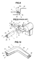
- Fig. 9 there is shown the conventional device for extruding the above-mentioned weather strip 1, which is described in, for example, Japanese Utility Model Second Provisional Publications 7-37937 and 7-54012.
- the conventional extruding device comprises a material extruder 10 from which a fluidized plastic material is fed to a fixed shaping die 11.
- the fixed shaping die 11 is formed with a main extruding opening 13 of a generally C-shaped cross section, which is communicated with the material extruder 10.
- the main opening 13 and the auxiliary opening 14 are merged to constitute a combined extruding opening 11' which has a shape corresponding to the cross section of the weather strip 1.
- the movable shaping plate 12 is horizontally driven by a drive device 15 through a shaft 15a.
- a wire 17 is driven by drive rollers 16 to pass through the main extruding opening 13 of the shaping die 11, which, as is seen from the drawing, serves as a reinforcing core member of the extruded weather strip 1.
- the fluidized plastic material is fed from the material extruder 10 to the fixed shaping die 11 allowing the combined extruding opening 11' to continuously extrude the material.
- an insufficiently cured weather strip 1 is produced, which includes the major portion 2 and the lip portion 3.
- the movable shaping plate 12 is slowly moved in one direction, the lip portion 3 gradually changes its position relative to the major portion 2 for formation of the water drip channel.
- the above-mentioned conventional extruding device has failed to exhibit a satisfactory extruding operation.
- the fluidized plastic material leaks to a thin clearance inevitably formed between the fixed shaping die 11 and the movable shaping plate 12, which not only obstructs smoothed movement of the movable shaping plate 12, but also causes formation of unsightly fin on the extruded weather strip 1.
- the amount of the material extruded through the smaller auxiliary extruding opening 14 is varied, which prevents formation of a uniform shape of the lip portion 3.
- EP-A-0 427 381 discloses a device in accordance with the pre-characterising part of claim 1.
- the present invention provides an extruding device as set forth in claim 1.
- a device for extruding a weather strip including an elongate major portion and an elongate lip portion,which is integrally formed on the major portion.
- the device comprises a material extruder which feeds a first material for the major portion; an additional material extruder which feeds a second material for the lip portion; a fixed shaping die formed with a main extruding opening from which the first material from the material extruder is extruded for formation of the major portion; and a movable shaping die formed with an auxiliary extruding opening from which the second material from the additional material extruder is extruded for formation of the lip portion, the movable shaping die being movable relative to the fixed shaping die, wherein the movable shaping die is located in front of the fixed shaping die and spaced from the same by a given distance.
- the weather strip 1 shown in Figs. 1 to 5 is a strip applied to a rear window of a motor vehicle. That is, the weather strip 1 is shaped to be arranged between a periphery of a rear window opening of a vehicle body 30 and that of a window pane G. Similar to the above-mentioned weather strip 1 of Fig. 10, the weather strip 1 comprises generally an elongate major portion 2 having a generally U-shaped cross section and an elongate lip portion 3 extending along the major portion 2. That is, as is seen from Fig. 1, the lip portion 3 projects outward from an upper surface 2b of an upper wall 2a of the major portion 2.
- the major portion 2 can be constructed of a soft or hard polyvinyl chloride (PVC) or a soft or hard polypropylene (PP), and the lip portion 3 can be constructed of a soft polyvinyl chloride (PVC) containing paraffin or butadiene acrylonitrile rubber (NBR).
- PVC polyvinyl chloride
- NBR butadiene acrylonitrile rubber
- Fig. 4 which shows the sectional view taken along the line A-A of Fig. 3, the upper part 3a of the lip portion 3 arranged at a horizontally extending upper portion of the weather strip 1 projects outward from a middle part of the major portion 2.
- a leading edge 3c of the upper part 3a of the lip portion 3 is pressed against a wall 31a defined by a recessed rear edge portion of a roof panel 31, which portion bounds a horizontally extending upper periphery of the rear window opening.
- Fig. 5 which shows the sectional view taken along the line B-B of Fig. 3, the side part 3b of the lip portion 3 arranged at each side portion of the weather strip 1 projects outward from a lower part of the major portion 2.
- a leading edge 3d of the side part 3b of the lip portion 3 is pressed against a wall 32a defined by a recessed rear edge portion of a rear pillar panel 32, which portion bounds a side periphery of the rear window opening.
- each side part 3b of the lip portion 3 is gradually raised as the distance from the upper part 3a increases, which thus constitutes a water drip channel at a generally upper half of the side part 3b between the side part of the window pane G and that of the rear window opening.
- Fig. 1 there is shown the extruding device of the present invention, by which the above-mentioned weather strip 1 is produced.
- the extruding device comprises first and second material extruders 24 and 25 from which a fluidized material for soft or hard polyvinyl chloride (PVC) is fed to a fixed shaping die 21.
- the fixed shaping die 21 is formed with a main extruding opening 23 of a generally C-shaped cross section, which is communicated with the two material extruders 24 and 25 through respective passages.
- a movable shaping die 22 In front of the fixed shaping die 21, there is horizontally movably arranged a movable shaping die 22 which is driven by a drive device 27 through a shaft 27a.
- the movable shaping die 22 is formed with an auxiliary extruding opening 26 which is communicated with a third material extruder 28 through a flexible feeding tube 29.
- the third material extruder 28 feeds the movable shaping die 22 with a fluidized material for soft polyvinyl chloride (PVC) containing paraffin or butadiene.
- PVC polyvinyl chloride
- the movable shaping die 22 is arranged at a certain distance L from the fixed shaping die 21.
- the distance L is so determined as to permit the major portion 2 extruded from the main extruding opening 23 to become stable in dimension and shape while keeping the highly heated fluidized condition.
- the distance L is so determined as to permit the major portion 2 extruded from the opening 23 to complete its shrinkage until the time when the same reaches to the movable shaping die 22.
- the distance L should be changed depending on the materials for the major portion 2. Experiments have revealed that when the distance L is about 30mm to about 200 mm, satisfactory result is expected.
- a wire 17 is driven by drive rollers (not shown) to pass through the main extruding opening 23 of the fixed shaping die 21, which serves as a reinforcing core member of the extruded weather strip 1.
- Designated by numeral 40 is a supporter having a rounded upper portion on which the extruded weather strip 1 is slidably supported. As shown, the supporter 40 is positioned just below the movable shaping die 22.
- the first and second material extruders 24 and 25 feed the fixed shaping die 21 with a fluidized plastic material (PVC) to allow the main extruding opening 23 to continuously extrude the major portion 2 of the weather strip 1.
- PVC fluidized plastic material
- the extruded major portion 2 travels toward the movable shaping die 22 and, after a while, comes to a position just below the movable shaping die 22.
- the extruded major portion 2 from the main extruding opening 23 has become stable in dimension and shape until the time when the same reaches the movable shaping die 22. That is, during the time for which the major portion 2 travels from the main extruding opening 23 to the movable shaping die 22, the major portion 2 has completed its shrinkage while keeping the highly heated fluidized condition.
- the third material extruder 28 feeds the movable shaping die 22 with a fluidized plastic material (for soft PVC) to allow the auxiliary extruding opening 26 to continuously extrude the lip portion 3 onto the upper surface 2b of the upper wall 2a of the major portion 2. With this, an insufficiently cured weather strip 1 is produced, which includes the major portion 2 and the lip portion 3.
- a fluidized plastic material for soft PVC
- the movable shaping die 22 is slowly moved in one direction, that is, leftward in case of the illustrated embodiment. With this, the lip portion 3 gradually changes its position relative to the major portion 2 for formation of the water drip channel.
- a pivot mechanism (not shown) may be employed for pivoting the movable shaping die 22 about an imaginary axis which axially passes through a lowermost part of the auxiliary extruding opening 26 and extends in parallel with the direction along which the extruded weather strip 1 travels.
- Figs. 6 to 8 show a weather strip 1 which is applied to a windshield (or front window) of a motor vehicle. That is, the weather strip 1 of these drawings is shaped to be arranged between a periphery of a windshield opening of a vehicle body 30 and that of a windshield G.
- the upper part 3a of the lip portion 3 extends outward from an upper portion of the upper wall 2a of the major portion 2, and the leading edge 3c of the upper part 3a is pressed against an upper part of a wall 33a defined by a recessed front edge portion of a roof panel 31. With this, a flush-surface arrangement is achieved between the upper part of the weather strip 1 and the roof panel 31.
- each side part 3b of the lip portion 3 is gradually lowered as the distance from the upper part 3a increases, which constitutes a water drip channel between the side part of the windshield G and that of the windshield opening of the vehicle body 30.
- the major portion 2 of the weather strip 1 extruded from the main extruding opening 23 can become stable in dimension and shape until the time when the lip portion 3 is extruded onto the major portion 2.
- the weather strip 1 produced by the invention can exhibit a high precision in dimension and shape.
- the lip portion 3 can be constructed of a material different from that of the major portion 2. This advantage is not possessed by the conventional extruding device of Fig. 9.
- the inclination angle of the lip portion 3 relative to the major portion 2 is easily changed.
- the produced weather strip 1 can have a shape optimum to the portion to which the same is applied.
Landscapes
- Engineering & Computer Science (AREA)
- Mechanical Engineering (AREA)
- Manufacturing & Machinery (AREA)
- Extrusion Moulding Of Plastics Or The Like (AREA)
Description
- The present invention relates to extruding devices for extruding an automotive plastic article, and more particularly to extruding devices for extruding an automotive weather strip which is arranged between a periphery of an automotive window opening and that of a window pane.
- In order to clarify the task of the present invention, an automotive weather strip and a conventional device for extruding the same will be briefly described with reference to Figs. 9 and 10 of the accompanying drawings.
- In Fig. 10, there is partially shown the automotive weather strip 1 which is to be arranged between a periphery of a window opening of a vehicle (not shown) and that of a window pane (not shown). The weather strip 1 is constructed of an integrally molded plastic, and comprises generally an elongate
major portion 2 which has a generally U-shaped cross section and anelongate lip portion 3 which extends along themajor portion 2. As shown, thelip portion 3 projects outward from anupper surface 2b of anupper wall 2a of themajor portion 2. Designated bynumerals lip portion 3 which are to be placed at upper and side portions of the window opening, respectively. Upon assembly, themajor portion 2 is tightly received on a peripheral edge of the window pane and thelip portion 3 is put on a recessed peripheral portion of the window opening. Due to provision of such recessed peripheral portion, a so-called flush-surface arrangement is achieved between theupper part 3a of the weather strip 1 and a body of the vehicle. As shown, theside part 3b of thelip portion 3 is gradually lowered as the distance from theupper part 3a increases, which constitutes a water drip channel between a side part of the window pane and that of the window opening of the vehicle body. - In Fig. 9, there is shown the conventional device for extruding the above-mentioned weather strip 1, which is described in, for example, Japanese Utility Model Second Provisional Publications 7-37937 and 7-54012.
- The conventional extruding device comprises a
material extruder 10 from which a fluidized plastic material is fed to a fixed shaping die 11. The fixed shaping die 11 is formed with a main extruding opening 13 of a generally C-shaped cross section, which is communicated with thematerial extruder 10. On a front surface of the shaping die 11, there is horizontally movably arranged amovable shaping plate 12 which is formed with anauxiliary extruding opening 14. As shown, when themovable shaping plate 12 is properly placed on the fixed shaping die 11, themain opening 13 and theauxiliary opening 14 are merged to constitute a combined extruding opening 11' which has a shape corresponding to the cross section of the weather strip 1. Themovable shaping plate 12 is horizontally driven by adrive device 15 through a shaft 15a. Awire 17 is driven bydrive rollers 16 to pass through the main extruding opening 13 of the shaping die 11, which, as is seen from the drawing, serves as a reinforcing core member of the extruded weather strip 1. - In operation, the fluidized plastic material is fed from the
material extruder 10 to the fixed shaping die 11 allowing the combined extruding opening 11' to continuously extrude the material. With this, an insufficiently cured weather strip 1 is produced, which includes themajor portion 2 and thelip portion 3. When, during this extrusion, themovable shaping plate 12 is slowly moved in one direction, thelip portion 3 gradually changes its position relative to themajor portion 2 for formation of the water drip channel. - However, due to its inherent construction, the above-mentioned conventional extruding device has failed to exhibit a satisfactory extruding operation. In fact, during operation, it has often occurred that the fluidized plastic material leaks to a thin clearance inevitably formed between the fixed shaping die 11 and the
movable shaping plate 12, which not only obstructs smoothed movement of themovable shaping plate 12, but also causes formation of unsightly fin on the extruded weather strip 1. Furthermore, during movement of themovable shaping plate 12, it has often occurred that due to a certain viscosity of the fluidized plastic material, the amount of the material extruded through the smallerauxiliary extruding opening 14 is varied, which prevents formation of a uniform shape of thelip portion 3. - In order to eliminate the above-mentioned drawbacks, the applicants have thought out a measure which is described in Japanese Patent First Provisional Publication 8-156584. In this published measure, a movable shaping die connected to an additional material extruder is employed for extruding the
lip portion 3 onto themajor portion 2. - However, even the extruding device of this publication has failed to exhibit a satisfied extruding operation. That is, in this measure, joining the
extruded lip portion 3 from the movable shaping die to themajor portion 2 is carried out at the time when themajor portion 2 is just extruded from the main shaping die. As is known, the fluidized plastic material just extruded is very unstable in dimension and shape, that is, such plastic material is subjected to a shrinkage. Thus, joining thelip portion 3 to such unstablemajor portion 2 inevitably lowers the dimensional stability and dimensional precision of the extruded weather strip 1. - It would therefore be desirable to be able to provide an extruding device for extruding an automotive weather strip, which is free of the above-mentioned drawbacks.
- EP-A-0 427 381 discloses a device in accordance with the pre-characterising part of claim 1.
- The present invention provides an extruding device as set forth in claim 1.
- According to the present invention, there is provided a device for extruding a weather strip including an elongate major portion and an elongate lip portion,which is integrally formed on the major portion. The device comprises a material extruder which feeds a first material for the major portion; an additional material extruder which feeds a second material for the lip portion; a fixed shaping die formed with a main extruding opening from which the first material from the material extruder is extruded for formation of the major portion; and a movable shaping die formed with an auxiliary extruding opening from which the second material from the additional material extruder is extruded for formation of the lip portion, the movable shaping die being movable relative to the fixed shaping die, wherein the movable shaping die is located in front of the fixed shaping die and spaced from the same by a given distance.
- Other objects and advantages of the present invention will become apparent from the following description when taken in conjunction with the accompanying drawings, in which:
- Fig. 1 is a perspective view of an extruding device of the present invention;
- Fig. 2 is a rear but partial view of a motor vehicle, showing a weather strip to be applied to a rear window of the vehicle, the weather strip being produced by the extruding device of the invention;
- Fig. 3 is a rear view of the motor vehicle, showing the weather strip properly applied to the rear window of the vehicle;
- Fig. 4 is an enlarged sectional view taken along the line A-A of Fig. 3;
- Fig. 5 is an enlarged sectional view taken along the line B-B of Fig. 3;
- Fig. 6 is a front but partial view of a motor vehicle, showing a weather strip to be applied to a windshield of the vehicle, the weather strip being produced by the extruding device of the invention;
- Fig. 7 is a front view of the motor vehicle, showing the weather strip properly applied to the windshield of the vehicle;
- Fig. 8 is an enlarged sectional view taken along the line C-C of Fig. 7;
- Fig. 9 is a view similar to Fig. 1, but showing a conventional extruding device; and
- Fig. 10 is a perspective but partial view of a weather strip produced by the conventional extruding device of Fig. 9.
-
- Before describing the construction of an extruding device of the present invention, a weather strip 1 produced by the device will be described for ease of understanding the extruding device.
- As is understood from Fig. 2, the weather strip 1 shown in Figs. 1 to 5 is a strip applied to a rear window of a motor vehicle. That is, the weather strip 1 is shaped to be arranged between a periphery of a rear window opening of a
vehicle body 30 and that of a window pane G. Similar to the above-mentioned weather strip 1 of Fig. 10, the weather strip 1 comprises generally an elongatemajor portion 2 having a generally U-shaped cross section and anelongate lip portion 3 extending along themajor portion 2. That is, as is seen from Fig. 1, thelip portion 3 projects outward from anupper surface 2b of anupper wall 2a of themajor portion 2. - For the reason which will be described hereinafter, the
major portion 2 can be constructed of a soft or hard polyvinyl chloride (PVC) or a soft or hard polypropylene (PP), and thelip portion 3 can be constructed of a soft polyvinyl chloride (PVC) containing paraffin or butadiene acrylonitrile rubber (NBR). - As is seen from Fig. 2, upon assembly, the
major portion 2 tightly received on the peripheral edge of the window pane G with an adhesive applied therebetween, and thelip portion 3 is put on a recessed peripheral portion of the rear window opening of thevehicle body 30. - As is understood from Figs. 2 and 4, particularly Fig. 4 which shows the sectional view taken along the line A-A of Fig. 3, the
upper part 3a of thelip portion 3 arranged at a horizontally extending upper portion of the weather strip 1 projects outward from a middle part of themajor portion 2. As is seen from Fig. 4, a leadingedge 3c of theupper part 3a of thelip portion 3 is pressed against awall 31a defined by a recessed rear edge portion of aroof panel 31, which portion bounds a horizontally extending upper periphery of the rear window opening. - As is understood from Figs. 2, 3, and 5, particularly Fig. 5 which shows the sectional view taken along the line B-B of Fig. 3, the
side part 3b of thelip portion 3 arranged at each side portion of the weather strip 1 projects outward from a lower part of themajor portion 2. As is seen from Fig. 5, a leadingedge 3d of theside part 3b of thelip portion 3 is pressed against a wall 32a defined by a recessed rear edge portion of arear pillar panel 32, which portion bounds a side periphery of the rear window opening. - As is understood from Fig. 2, each
side part 3b of thelip portion 3 is gradually raised as the distance from theupper part 3a increases, which thus constitutes a water drip channel at a generally upper half of theside part 3b between the side part of the window pane G and that of the rear window opening. - In Fig. 1, there is shown the extruding device of the present invention, by which the above-mentioned weather strip 1 is produced.
- The extruding device comprises first and second material extruders 24 and 25 from which a fluidized material for soft or hard polyvinyl chloride (PVC) is fed to a
fixed shaping die 21. The fixed shaping die 21 is formed with a main extruding opening 23 of a generally C-shaped cross section, which is communicated with the twomaterial extruders - In front of the fixed shaping die 21, there is horizontally movably arranged a
movable shaping die 22 which is driven by adrive device 27 through ashaft 27a. The movable shaping die 22 is formed with an auxiliary extrudingopening 26 which is communicated with athird material extruder 28 through aflexible feeding tube 29. The third material extruder 28 feeds the movable shaping die 22 with a fluidized material for soft polyvinyl chloride (PVC) containing paraffin or butadiene. - It is to be noted that the movable shaping die 22 is arranged at a certain distance L from the fixed shaping die 21. The distance L is so determined as to permit the
major portion 2 extruded from the main extrudingopening 23 to become stable in dimension and shape while keeping the highly heated fluidized condition. In other words, the distance L is so determined as to permit themajor portion 2 extruded from theopening 23 to complete its shrinkage until the time when the same reaches to the movable shaping die 22. Thus, the distance L should be changed depending on the materials for themajor portion 2. Experiments have revealed that when the distance L is about 30mm to about 200 mm, satisfactory result is expected. - A
wire 17 is driven by drive rollers (not shown) to pass through the main extruding opening 23 of the fixed shaping die 21, which serves as a reinforcing core member of the extruded weather strip 1. - Designated by
numeral 40 is a supporter having a rounded upper portion on which the extruded weather strip 1 is slidably supported. As shown, thesupporter 40 is positioned just below the movable shaping die 22. - In the following, operation of the extruding device of the invention for extruding the weather strip 1 will be described with reference to Fig. 1.
- The first and
second material extruders major portion 2 of the weather strip 1. The extrudedmajor portion 2 travels toward the movable shaping die 22 and, after a while, comes to a position just below the movable shaping die 22. - It is now to be noted that, due to the certain distance L between the fixed and movable shaping dies 21 and 22, the extruded
major portion 2 from the main extruding opening 23 has become stable in dimension and shape until the time when the same reaches the movable shaping die 22. That is, during the time for which themajor portion 2 travels from the main extruding opening 23 to the movable shaping die 22, themajor portion 2 has completed its shrinkage while keeping the highly heated fluidized condition. - When the
major portion 2 comes to the position just below the movable shaping die 22, thethird material extruder 28 feeds the movable shaping die 22 with a fluidized plastic material (for soft PVC) to allow the auxiliary extruding opening 26 to continuously extrude thelip portion 3 onto theupper surface 2b of theupper wall 2a of themajor portion 2. With this, an insufficiently cured weather strip 1 is produced, which includes themajor portion 2 and thelip portion 3. - When the extruded weather strip 1 is brought up to show a given length, the movable shaping die 22 is slowly moved in one direction, that is, leftward in case of the illustrated embodiment. With this, the
lip portion 3 gradually changes its position relative to themajor portion 2 for formation of the water drip channel. - If desired, a pivot mechanism (not shown) may be employed for pivoting the movable shaping die 22 about an imaginary axis which axially passes through a lowermost part of the
auxiliary extruding opening 26 and extends in parallel with the direction along which the extruded weather strip 1 travels. - Figs. 6 to 8 show a weather strip 1 which is applied to a windshield (or front window) of a motor vehicle. That is, the weather strip 1 of these drawings is shaped to be arranged between a periphery of a windshield opening of a
vehicle body 30 and that of a windshield G. - As is best seen from Fig. 6, the
upper part 3a of thelip portion 3 extends outward from an upper portion of theupper wall 2a of themajor portion 2, and theleading edge 3c of theupper part 3a is pressed against an upper part of awall 33a defined by a recessed front edge portion of aroof panel 31. With this, a flush-surface arrangement is achieved between the upper part of the weather strip 1 and theroof panel 31. - As is understood from Figs. 6, 7, and 8, each
side part 3b of thelip portion 3 is gradually lowered as the distance from theupper part 3a increases, which constitutes a water drip channel between the side part of the windshield G and that of the windshield opening of thevehicle body 30. - In the following, advantages of the present invention will be described.
- First, due to the certain distance L defined between the fixed and movable shaping dies 21 and 22, the
major portion 2 of the weather strip 1 extruded from the main extruding opening 23 can become stable in dimension and shape until the time when thelip portion 3 is extruded onto themajor portion 2. Thus, the weather strip 1 produced by the invention can exhibit a high precision in dimension and shape. - Second, because the fixed and movable shaping dies 21 and 22 are spaced, maintenance work for them is easily made. In fact, cleaning of the main and
auxiliary extruding openings - Third, because the material for the
lid portion 3 is fed by aseparate material extruder 28, thelip portion 3 can be constructed of a material different from that of themajor portion 2. This advantage is not possessed by the conventional extruding device of Fig. 9. - Fourth, if, as is described hereinabove, a pivoting mechanism is employed for pivoting the movable shaping die 22, the inclination angle of the
lip portion 3 relative to themajor portion 2 is easily changed. In this case, the produced weather strip 1 can have a shape optimum to the portion to which the same is applied.
Claims (10)
- A device for extruding a weather strip (1) including an elongate major portion (2) and an elongate lip portion (3), the device comprising: main material extruding means (24,29); auxiliary material extruding means (28); a main shaping die (21) with a main extruding opening (23) from which the material fed by the main material extruding means (24,29) is extruded; and an auxiliary shaping die (22) with an auxiliary extruding opening (26) from which the material fed by the auxiliary material extruding means (28) is extruded, the auxiliary shaping die (22) being located in front of the main shaping die (21) and being spaced therefrom;
characterised in that the auxiliary shaping die (22) is movable relative to the main shaping die (21), the dies (21,22) being arranged such that material for formation of the major portion (2) is extruded from the main extruding opening (23) and material for formation of the lip portion (3) is extruded from the auxiliary extruding opening (26). - A device as claimed in claim 1, in which the space (L) between the said dies (21,22) is sufficient to permit the major portion (2) extruded from the main extruding opening (23) to become stable in shape while remaining hot and fluid.
- A device as claimed in claim 1 or 2, in which the main extruding opening (23) is generally U-shaped when viewed from in front.
- A device as claimed in any preceding claim, in which the main material extruding means comprises two material extruders (24,25) connected to the main extruding opening (23) of the main shaping die (21) through respective passages.
- A device as claimed in any preceding claim, in which the auxiliary material extruding means (28) is connected to the auxiliary extruding opening (26) of the auxiliary shaping die (22) through a flexible tube (29).
- A device as claimed in any preceding claim, including drive means (27) for moving the auxiliary shaping die (22) in a direction transverse to the direction along which the extruded major portion (2) from the main extruding opening (23) travels.
- A device as claimed in any preceding claim, including a supporter (40) which is positioned just below the auxiliary shaping die (22) to slidably support thereon the major portion (2) extruded from the main extruding opening (23).
- A device as claimed in claim 7, in which the supporter (40) has a rounded upper portion on which the extruded major portion (2) slides.
- A device as claimed in any preceding claim, in which the main extruding means (24,25) extrudes fluid material for forming a hard polyvinyl chloride and the auxiliary extruding means (28) extrudes fluid material for forming a soft polyvinyl chloride.
- A device as claimed in any preceding claim, in which the spacing (L) between the said dies (21,22) is approximately 30 mm to approximately 200 mm.
Applications Claiming Priority (3)
| Application Number | Priority Date | Filing Date | Title |
|---|---|---|---|
| JP108996/96 | 1996-04-30 | ||
| JP10899696A JP3652436B2 (en) | 1996-04-30 | 1996-04-30 | Wind molding for automobile and extrusion molding apparatus for the wind molding |
| JP10899696 | 1996-04-30 |
Publications (2)
| Publication Number | Publication Date |
|---|---|
| EP0805013A1 EP0805013A1 (en) | 1997-11-05 |
| EP0805013B1 true EP0805013B1 (en) | 2001-03-14 |
Family
ID=14498945
Family Applications (1)
| Application Number | Title | Priority Date | Filing Date |
|---|---|---|---|
| EP97302809A Expired - Lifetime EP0805013B1 (en) | 1996-04-30 | 1997-04-24 | Device for extruding automotive weather strip |
Country Status (4)
| Country | Link |
|---|---|
| US (1) | US5814352A (en) |
| EP (1) | EP0805013B1 (en) |
| JP (1) | JP3652436B2 (en) |
| DE (1) | DE69704228T2 (en) |
Families Citing this family (5)
| Publication number | Priority date | Publication date | Assignee | Title |
|---|---|---|---|---|
| US6106047A (en) * | 1996-08-21 | 2000-08-22 | Kinugawa Rubber Ind. Co., Ltd. | Window molding, method and apparatus for producing same |
| AU719275B2 (en) * | 1996-11-21 | 2000-05-04 | Marley Mouldings Inc. | Weatherstrip product formed by sequential extrusion of cellular and non-cellular plastic resins |
| US6231327B1 (en) * | 1999-07-02 | 2001-05-15 | Mastercraft Industries, L.P. | Composite extrusion and patterning machine for irregularly curved edges and method of manufacture thereof |
| US6458301B1 (en) * | 2001-08-27 | 2002-10-01 | Schlegel Corporation | Method for forming weatherseals from an interchangeable insert die assembly |
| CN112356475B (en) * | 2020-12-04 | 2022-07-15 | 德清尚邑塑料制品有限公司 | Production process of slider type sealing bag sealing strip, jig and extrusion equipment thereof |
Family Cites Families (19)
| Publication number | Priority date | Publication date | Assignee | Title |
|---|---|---|---|---|
| US3067455A (en) * | 1956-04-19 | 1962-12-11 | Standard Products Co | Apparatus for making a window pane supporting and/or guiding structure |
| JPS5336567A (en) * | 1976-09-17 | 1978-04-04 | Kanegafuchi Chemical Ind | Method of producing magnet contained gasket |
| JPS5761543A (en) * | 1980-09-30 | 1982-04-14 | Toyoda Gosei Co Ltd | Extrusion coating of profile product and apparatus |
| JPS5876244A (en) * | 1981-10-30 | 1983-05-09 | Kazuhiko Okada | Method and apparatus for extrusion molding several member |
| US4510715A (en) * | 1982-11-12 | 1985-04-16 | Donat Flamand Inc. | Composite weather strip for windows and doors |
| JPS62222825A (en) * | 1986-03-25 | 1987-09-30 | Kinugawa Rubber Ind Co Ltd | Apparatus for opening and closing outflow part of elastic material |
| JPH01314153A (en) * | 1988-06-13 | 1989-12-19 | Tokai Kogyo Kk | Weather strip, and method and apparatus for manufacturing the same |
| JP2522997B2 (en) * | 1988-08-31 | 1996-08-07 | 豊田合成株式会社 | Method for forming a weatherstrip finish coating film |
| GB8827180D0 (en) * | 1988-11-21 | 1988-12-29 | Schlegel Uk Holdings | Composite extrusion |
| CA1323743C (en) * | 1989-01-27 | 1993-11-02 | Franz Purstinger | Dimensionally stable plastics sections |
| US5114517A (en) * | 1989-10-30 | 1992-05-19 | Schonstedt Instrument Company | Methods, apparatus and devices relating to magnetic markers for elongated hidden objects |
| US5221564A (en) * | 1989-11-03 | 1993-06-22 | The Standard Products Company | Integral hybrid molding and weatherstrip |
| US5137675A (en) * | 1991-05-13 | 1992-08-11 | Gencorp Inc. | Apparatus and method for coextruding materials having different temperature dependent properties |
| JPH0773893B2 (en) * | 1993-06-07 | 1995-08-09 | トキワケミカル工業株式会社 | Molding method for automotive weather strip |
| JPH0737937A (en) * | 1993-07-16 | 1995-02-07 | Matsushita Electric Ind Co Ltd | Bonding head |
| DE4326650A1 (en) * | 1993-08-09 | 1995-02-16 | Ver Glaswerke Gmbh | Method and devices for producing a glass pane provided with a molded-on frame made of a polymer |
| JP2749761B2 (en) * | 1993-08-09 | 1998-05-13 | 本田技研工業株式会社 | Powder forging method for high yield strength and high toughness aluminum alloy powder |
| US5645785A (en) * | 1993-08-09 | 1997-07-08 | Saint Gobain Vitrage | Device for extruding a polymer frame onto a plate-shaped object |
| JP3027100B2 (en) * | 1994-12-01 | 2000-03-27 | 鬼怒川ゴム工業株式会社 | Vehicle window molding mounting structure and method of manufacturing the same |
-
1996
- 1996-04-30 JP JP10899696A patent/JP3652436B2/en not_active Expired - Fee Related
-
1997
- 1997-04-22 US US08/844,759 patent/US5814352A/en not_active Expired - Fee Related
- 1997-04-24 EP EP97302809A patent/EP0805013B1/en not_active Expired - Lifetime
- 1997-04-24 DE DE69704228T patent/DE69704228T2/en not_active Expired - Fee Related
Also Published As
| Publication number | Publication date |
|---|---|
| DE69704228D1 (en) | 2001-04-19 |
| JPH09295332A (en) | 1997-11-18 |
| US5814352A (en) | 1998-09-29 |
| DE69704228T2 (en) | 2001-10-25 |
| EP0805013A1 (en) | 1997-11-05 |
| JP3652436B2 (en) | 2005-05-25 |
Similar Documents
| Publication | Publication Date | Title |
|---|---|---|
| KR940000620B1 (en) | Molding member and manufacturing method | |
| US4765936A (en) | Method for the manufacture of a weather strip for motor vehicles | |
| EP0674987B1 (en) | Method and apparatus for producing an automobile windshield molding | |
| US5300346A (en) | Elongate plastic articles | |
| US5133537A (en) | Molding for windshield of automobile and its molding apparatus | |
| US5389423A (en) | Windshield molding for vehicles | |
| US5814352A (en) | Device for extruding automotive weather strip | |
| JPH06459B2 (en) | Wind molding and manufacturing method thereof | |
| US5203946A (en) | Method of, and apparatus for manufacturing elongate plastic articles | |
| CA2050727C (en) | Automobile windshield molding and the method of producing the same | |
| JP3239593B2 (en) | Vehicle window molding and manufacturing method | |
| JP3285334B2 (en) | Wind molding for vehicles and manufacturing method thereof | |
| JP3096110B2 (en) | Automotive wind molding and method of manufacturing the same | |
| AU618406B2 (en) | Method of, and apparatus for manufacturing elongate plastic articles | |
| JP3031083B2 (en) | Molding and manufacturing method thereof | |
| JP2963304B2 (en) | Wind molding for vehicles and manufacturing method thereof | |
| JP3178647B2 (en) | Extrusion molding equipment for automotive wind molding | |
| JP3153267B2 (en) | Molding and manufacturing method thereof | |
| EP0602320A1 (en) | A windshield molding for vehicles | |
| JP3061317B2 (en) | Automotive wind molding | |
| JPH0768624A (en) | Method for manufacturing window glass molding | |
| JPH058280A (en) | Vehicle molding and its manufacturing method and device | |
| JP3065156B2 (en) | Automotive wind molding and method of manufacturing the same | |
| JP2823982B2 (en) | Automotive door molding and method of manufacturing the same | |
| JPH0699734A (en) | Window molding for automobile and its manufacture |
Legal Events
| Date | Code | Title | Description |
|---|---|---|---|
| PUAI | Public reference made under article 153(3) epc to a published international application that has entered the european phase |
Free format text: ORIGINAL CODE: 0009012 |
|
| 17P | Request for examination filed |
Effective date: 19970509 |
|
| AK | Designated contracting states |
Kind code of ref document: A1 Designated state(s): DE GB IT |
|
| 17Q | First examination report despatched |
Effective date: 19990616 |
|
| GRAG | Despatch of communication of intention to grant |
Free format text: ORIGINAL CODE: EPIDOS AGRA |
|
| GRAG | Despatch of communication of intention to grant |
Free format text: ORIGINAL CODE: EPIDOS AGRA |
|
| GRAH | Despatch of communication of intention to grant a patent |
Free format text: ORIGINAL CODE: EPIDOS IGRA |
|
| GRAH | Despatch of communication of intention to grant a patent |
Free format text: ORIGINAL CODE: EPIDOS IGRA |
|
| GRAA | (expected) grant |
Free format text: ORIGINAL CODE: 0009210 |
|
| AK | Designated contracting states |
Kind code of ref document: B1 Designated state(s): DE GB IT |
|
| RIN1 | Information on inventor provided before grant (corrected) |
Inventor name: SUMITO, ICHINOHE, KINUGAWA RUBBER IND. CO., LTD. Inventor name: HIROYOSHI, IMURA, KINUGAWA RUBBER IND. CO. LTD. |
|
| REF | Corresponds to: |
Ref document number: 69704228 Country of ref document: DE Date of ref document: 20010419 |
|
| ITF | It: translation for a ep patent filed | ||
| EN | Fr: translation not filed | ||
| REG | Reference to a national code |
Ref country code: GB Ref legal event code: IF02 |
|
| PLBE | No opposition filed within time limit |
Free format text: ORIGINAL CODE: 0009261 |
|
| STAA | Information on the status of an ep patent application or granted ep patent |
Free format text: STATUS: NO OPPOSITION FILED WITHIN TIME LIMIT |
|
| 26N | No opposition filed | ||
| PGFP | Annual fee paid to national office [announced via postgrant information from national office to epo] |
Ref country code: GB Payment date: 20040421 Year of fee payment: 8 |
|
| PGFP | Annual fee paid to national office [announced via postgrant information from national office to epo] |
Ref country code: DE Payment date: 20040506 Year of fee payment: 8 |
|
| PG25 | Lapsed in a contracting state [announced via postgrant information from national office to epo] |
Ref country code: IT Free format text: LAPSE BECAUSE OF NON-PAYMENT OF DUE FEES Effective date: 20050424 Ref country code: GB Free format text: LAPSE BECAUSE OF NON-PAYMENT OF DUE FEES Effective date: 20050424 |
|
| PG25 | Lapsed in a contracting state [announced via postgrant information from national office to epo] |
Ref country code: DE Free format text: LAPSE BECAUSE OF NON-PAYMENT OF DUE FEES Effective date: 20051101 |
|
| GBPC | Gb: european patent ceased through non-payment of renewal fee |
Effective date: 20050424 |