EP0804986B1 - Cutting element - Google Patents
Cutting element Download PDFInfo
- Publication number
- EP0804986B1 EP0804986B1 EP97107298A EP97107298A EP0804986B1 EP 0804986 B1 EP0804986 B1 EP 0804986B1 EP 97107298 A EP97107298 A EP 97107298A EP 97107298 A EP97107298 A EP 97107298A EP 0804986 B1 EP0804986 B1 EP 0804986B1
- Authority
- EP
- European Patent Office
- Prior art keywords
- cutting element
- cutting
- chucking device
- workpiece
- machined
- Prior art date
- Legal status (The legal status is an assumption and is not a legal conclusion. Google has not performed a legal analysis and makes no representation as to the accuracy of the status listed.)
- Expired - Lifetime
Links
Images

Classifications
-
- B—PERFORMING OPERATIONS; TRANSPORTING
- B23—MACHINE TOOLS; METAL-WORKING NOT OTHERWISE PROVIDED FOR
- B23B—TURNING; BORING
- B23B5/00—Turning-machines or devices specially adapted for particular work; Accessories specially adapted therefor
- B23B5/16—Turning-machines or devices specially adapted for particular work; Accessories specially adapted therefor for bevelling, chamfering, or deburring the ends of bars or tubes
- B23B5/166—Devices for working electrodes
-
- B—PERFORMING OPERATIONS; TRANSPORTING
- B23—MACHINE TOOLS; METAL-WORKING NOT OTHERWISE PROVIDED FOR
- B23B—TURNING; BORING
- B23B5/00—Turning-machines or devices specially adapted for particular work; Accessories specially adapted therefor
- B23B5/16—Turning-machines or devices specially adapted for particular work; Accessories specially adapted therefor for bevelling, chamfering, or deburring the ends of bars or tubes
- B23B5/167—Tools for chamfering the ends of bars or tubes
- B23B5/168—Tools for chamfering the ends of bars or tubes with guiding devices
-
- B—PERFORMING OPERATIONS; TRANSPORTING
- B23—MACHINE TOOLS; METAL-WORKING NOT OTHERWISE PROVIDED FOR
- B23B—TURNING; BORING
- B23B2270/00—Details of turning, boring or drilling machines, processes or tools not otherwise provided for
- B23B2270/22—Externally located features, machining or gripping of external surfaces
Definitions
- GB-A-2279 600 shows a cutting element with all the features of the preamble of Claim 1. Furthermore, this cutting element has cutting edges 106c, 106d and 106e, which are each straight (see Figure 3 in conjunction with page 6), and on the respective flat rake faces Connect 106c1 and 106d1 (see Figures 6 and 7), as well as open spaces 106c2 and 106d2. The clearance angles are not defined.
- the main advantage of the invention is that with Using the cutting element workpieces in a single machining process can be edited without being in the area the axis of rotation of the workpiece to be machined Usual pimples from the rest of the flat machined area survives.
- the cutting element preferably consists of rod material, preferably from a rectangular profile that according to the Basic processing, namely cutting to length, machining (eroding) the Recesses and grinding the open areas only one Hardening process must be subjected. Another editing is in contrast to conventional cutting materials, such as for example indexable inserts, not necessary.
- the cutting element preferably consists of a cutting part with two on opposite sides of the cutting part arcuate recesses arranged offset from one another and from clamping parts arranged at the ends of the cutting part, so that the center of gravity of the cutting element is the intersection corresponds to the free area of the cutting part.
- the in essential arcuate recesses are in relation to the Center of gravity of the cutting element arranged symmetrically.
- the cutting element is particularly suitable for machining spherical workpieces. Because due to each other on one namely the main cutting edges arranged offset at the highest level and the opposing open spaces are surprisingly evident that then the workpiece to be machined automatically is centered when the cutting element is around its Rotation axis that passes through the point at which the two open spaces intersect (the Middle and the center of gravity of the cutting element).
- the clamping device for the cutting element according to the invention is very simple. It essentially consists of two jaws, the jaws having recesses, which accommodate the respective clamping parts of the cutting element and these clamping parts in the assembled state of the clamping device include so that the cutting element is in the correct position is positioned in the clamping device.
- the cutting element is in the order of one Rotation axis rotating chuck held that the Center of gravity of the cutting element on the axis of rotation of the Clamping device is located and the axis of rotation perpendicular to Longitudinal extension of the cutting element runs.
- the tensioning device itself is preferably part of a Device for machining workpieces made of metal or Plastic.
- the tensioning device according to the invention with the new cutting element can be particularly advantageous in one Device for the mechanical removal of deposits
- Deposits that accumulate in the Welding is created and attached to the welding electrode in the floor area deposit, can be easily removed. Because for it is the achievement of high quality welds it is important that the welding electrodes, especially in their base area, in contact with the material to be welded comes, are plan, i.e. should have no pimples.
- Another major advantage of the cutting element and the Clamping device for this cutting element is that with a single cutting element processed two workpieces simultaneously can be. This is made possible by the fact that the cutting element has four main cutting edges, which by the arranged on the different sides of the profile and mutually offset substantially arcuate recesses are formed, each with two main cutting edges one side of the cutting element is present. On the other hand are two opposite in the clamping device Area of the axis of rotation of the clamping device Openings are provided that allow simultaneous access to the allow machining workpieces.
- the clamping device with the cutting element can be combined with other machining processes.
- this clamping device with the cutting element can be inserted into the processing head of the applicant's aforementioned device without having to do without the additional cutting elements already provided there. This enables simultaneous machining of a welding electrode in the bottom and side area.
- the user is free to either equip a device with a combined bottom and side treatment, or he can choose to only process the bottom of a welding electrode or only the sides.
- the cutting element 1, 100 essentially consists from at least one cutting part and at least one Clamping part.
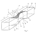
- the cutting element 1 comprises a cutting part 4 and each arranged on the sides of the cutting part 4 Clamping parts 2, 3, the cutting element 1 itself from one elongated rectangular profile.
- the cutting part 4 comprises a total of four main cutting edges 16, 17, 18, 19, wherein two main cutting edges 16, 17 and 18, 19 in one plane are arranged.
- the main cutting edges 16, 17, 18, 19 arise on the edges of adjacent open spaces 10, 11 and Rake faces 12, 13 and lie in the plane of the upper sides 20, 21 of the clamping parts 2, 3, so that between the tops 20, 21st and the open spaces 10, 11 steps with a sharp acute angle Surface.
- the rake faces are created 12, 13 of the cutting element 1 by producing one substantially arcuate recess 8, 9 in the side surfaces 14, 15 of the cutting element 1 shown in FIG. 1, the Rake faces 12, 13 correspond to the arc surface.
- the essentially arcuate recesses 8, 9 over the whole Profile cross section of the cutting part 4 is provided.
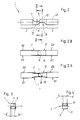
- the free surface 10, 11 is ground by grinding the top 20, 21, with a permissible roughness depth of max. 0.1 ⁇ m should not be exceeded.
- the inclination of the free surface is preferably 2 ° starting from the respective main cutting edge 16, 17, 18, 19 sloping downwards.
- the two are substantially arcuate Recesses 8, 9 arranged offset from one another.
- a recess 8 in one side surface 14 the other recess 9 on the other side surface 15 so is arranged that the main cutting edges 16, 17 and 18, 19 from Center of the cutting element 1, which at the same time Center of gravity S of the cutting element 1 forms at the same distance are removed.
- the main cutting edges 16, 17 are closed the main cutting edges 17, 18 point symmetrical with respect to the Center of gravity S arranged.
- the open spaces 10, 11 are arcuate so that whose intersection is the center of gravity S of the cutting element 1 corresponds, assuming that the axis of rotation R of the cutting element 1, the center of gravity S perpendicular to the longitudinal extent the cutting element, i.e. perpendicular to the top 20, 21 penetrates.
- the first embodiment of the cutting element 1 is suitable either two workpieces at the same time, i.e. each with the main cutting edges 16, 17 and 18, 19, or, if only one workpiece is machined, after wear one main cutting 16, 17 the cutting element 1 by 180 ° to rotate so that the other main cutting edges 18, 19 are used come.
- the second embodiment of a cutting element 100, the 5-7 is different from that first embodiment in that the essentially arcuate recesses 108, 109 do not cover the entire Extend profile cross section. This leads to this cutting element 100 only two main cutting edges 116, 117 having. This cutting element 100 takes place above all Use when only short chips are involved in the machining process arise.
- 5-7 are essentially the reference numerals 2-4 have been adopted, but with the difference a reference numeral number larger by 100 to to make it clear that it is compared to FIGS. 2-4 is another embodiment.
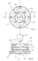
- This tensioning device 200 is suitable themselves for insertion into a device that is a drive for provides the tensioner 200 so that the tensioner 200 is rotated about its axis of rotation R.
- the essentially cylindrical clamping device 200 itself consists in one embodiment of two opposite Jaws 201, 202 which are in the clamped state enclose the cutting element 1,100 between them.
- the Clamping tension is by on the circumference of the tensioning device 200 distributed clamping screws 208 reached that both one jaw 201 and the other jaw 202 penetrate.
- the cutting element 1, 100 is preferably positioned so that the center of gravity S of the cutting element 1, 100 on the axis of rotation R of the tensioning device 200 lies.
- the underside 210 has one clamping device 200 each funnel-shaped opening 211, 212 with a funnel base 213 on which the workpiece 300 to be machined has access to the Cutting element 1, 100 allows.
- This funnel-shaped opening 211, 212 is designed so that in the funnel base 213 Bore is provided, the one the outer profile of the Cutting part 4, 104 of the cutting element 1, 100 corresponds to and on the other hand, is dimensioned so that during the machining process chips are easily removed can.
- the tapering toward the funnel base 213 is preferred Wall designed so that it is the negative form of the to be processed Workpiece 300 corresponds. This has the advantage that a precise delivery of the workpiece 300 in the direction of Cutting elements 1, 100 is not required because the workpiece 300 is processed until it rests on the wall. Then another delivery of the to be processed Workpiece 300 in the direction of the cutting element 1, 100 not more is possible.
- any type of clamping device is conceivable that either Holding the cutting element in the correct position, whereby the one to be machined Workpiece rotates relative to this, or -how described- the tensioning device with the cutting element turns towards the stationary workpiece.
Landscapes
- Engineering & Computer Science (AREA)
- Mechanical Engineering (AREA)
- Dicing (AREA)
- Milling Processes (AREA)
- Cutting Tools, Boring Holders, And Turrets (AREA)
Description
Die Erfindung betrifft ein Schneidelement für eine Spanneinrichtung insbesondere zum Zerspanen von Werkstücken aus Metall oder Kunststoff, bestehend aus einem länglichen Körper mit
- mindestens einem Schneidteil mit mindestens einer Hauptschneide,wobei das Schneidteil mindestens eine Spanfläche und mindestens eine Freifläche umfaßt und die Hauptschneide des Schneidteils jeweils an der Kante von aneinander angrenzenden Spanflächen und Freiflächen gebildet ist und
- mindestens einem mit dem Schneidteil einstückig verbundenen Klemmteil zum Spannen des Schneidelements in der Spanneinrichtung
- at least one cutting part with at least one main cutting edge, wherein the cutting part comprises at least one rake face and at least one free face and the main cutting edge of the cutting part is in each case formed on the edge of adjacent rake faces and free faces and
- at least one clamping part connected in one piece to the cutting part for clamping the cutting element in the clamping device
Die GB-A-2279 600 zeigt ein Schneidelement mit allen Merkmalen des Oberbegriffs des
Anspruchs 1. Weiter weist dieses Schneidelement Schneidkanten 106c, 106d und 106e auf,
die jeweils gerade sind (vgl. Figur 3 i.V.m. Seite 6), und an die jeweils ebene Spanflächen
106c1 bzw. 106d1 (vgl. Figuren 6 und 7), sowie Freiflächen 106c2 bzw. 106d2 anschließen.
Die Freiwinkel sind nicht definiert.GB-A-2279 600 shows a cutting element with all the features of the preamble of
Bei spanenden Verfahren mit Schneidelementen der angegebenen Art werden von einem zu bearbeitenden Werkstück Stoffteilchen (Späne) auf mechanischem Wege abgetrennt, um bestimmte Werkstückformen, Werkstücktoleranzen und Werkstückoberflächen zu erreichen. Das Abtrennen der Späne vom Werkstück erfolgt durch das in seiner Form eindeutig geometrisch bestimmte Schneidteil. Dieses Schneidteil ist der im Zerpanungsprozeß aktive Teil des Werkzeugs. Im rechtwinkligen Bezugssystem ergeben sich die für den Zerpanungsprozeß wichtigen Werkzeugwinkel, nämlich Freiwinkel α und Spanwinkel γ. Zusammen mit dem zwischen Freiwinkel α und Spanwinkel γ liegenden Keilwinkel β ergibt die Summe aller Winkel immer 90°. Die Flächen, über die der Span während des Bearbeitungsprozesses abläuft, werden Spanflächen genannt, diejenigen, die der Spanfläche gegenüber angeordnet sind, nennt man Freiflächen. Die Durchdringung der Ebenen von Span- und Freifläche - also deren gemeinsame Kante - wird aufgrund ihrer Funktion auch Hauptschneide genannt. Mit dieser Hauptschneide wird das Werkstück bearbeitet. For cutting processes with cutting elements of the specified Kind of become from a workpiece to be machined (Chips) separated mechanically to form certain workpiece shapes, Workpiece tolerances and workpiece surfaces too to reach. The chips are separated from the workpiece by the clearly geometrically defined cutting part in its shape. This cutting part is the one active in the machining process Part of the tool. In the right-angled reference system the tool angles important for the machining process, namely clearance angle α and rake angle γ. Along with the between Clearance angle α and rake angle γ lying wedge angle β results in the sum of all angles always 90 °. The areas over which the chip expires during the machining process Called rake faces, those facing the rake face are called open spaces. The penetration of the Layers of chip and free surface - i.e. their common edge - is also called the main cutting edge due to its function. With the main cutting edge is used to machine the workpiece.
In der Regel werden zum spanenden Bearbeiten von Werkstücken aus Metall oder Kunststoff Wendeschneidplatten in den unterschiedlichsten Formen verwendet. Auch sie weisen alle die beschriebenen Merkmale auf. Es handelt sich dabei um drei- oder mehreckige, oder auch im Querschnitt runde Schneidelemente, die entweder an einem Ende oder über eine im Schneidelement vorgesehene Bohrung in einer Spanneinrichtung gehalten werden. Für die Bearbeitung des Werkstücks ist es entweder erforderlich, daß das Werkstück stillsteht und das Werkzeug sich um seine Rotationsachse dreht, oder das Werkzeug stillsteht und das Werkstück sich um seine Rotationsachse dreht.Usually used for machining workpieces Made of metal or plastic inserts in a wide variety Shapes used. They also show them all described features on. It is three or polygonal cutting elements or cutting elements that are round in cross section, either at one end or over one in the cutting element provided bore held in a clamping device become. For machining the workpiece it is either required that the workpiece is stationary and the tool rotates around its axis of rotation, or the tool stands still and the workpiece rotates around its axis of rotation.
Beim Stirn- oder Plandrehen eines Werkstücks wird bisher das zu bearbeitende Werkstück relativ zu dem Werkzeug (Schneidelement) in Drehung versetzt. Dabei wird abhängig vom Material des Werkzeugs und des Werkstücks das Werkzeug (Schneidelement) in Richtung der Rotationsachse des Werkzeugs zugestellt und zwar solange, bis die gewünschte Länge bzw. Form oder Oberfläche des Werkstücks erreicht ist. Nach Abschluß des Drehvorganges bleibt jedoch im Bereich der Rotationsachse immer ein Pickel stehen, der auch durch einen weiteren Drehvorgang nicht entfernt werden kann.So far, this has been the case when turning a face or face Workpiece to be machined relative to the tool (cutting element) spun. It depends on the material the tool and the workpiece the tool (cutting element) in the direction of the axis of rotation of the tool and until the desired length, shape or surface of the workpiece is reached. After completing the turning process however, always remains in the area of the axis of rotation a pimple standing by another turning process cannot be removed.
Sollte es aus technischen oder ästhetischen Gründen notwendig sein, diesen Pickel zu entfernen, so sind weitere kostenintensive Nacharbeiten, möglicherweise sogar von Hand notwendig.Should it be necessary for technical or aesthetic reasons be to remove this pimple, so are more expensive Reworking, possibly even necessary by hand.
Es besteht daher die Aufgabe, ein Schneidelement und eine Spanneinrichtung für das Schneidelement zur Verwendung in einer Vorrichtung zum Zerpanen von Werkstücken aus Metall oder Kunststoff zu schaffen, mit dem der Nachteil des Standes der Technik vermieden wird.There is therefore the task of a cutting element and a Clamping device for the cutting element for use in a device for machining metal workpieces or To create plastic with which the disadvantage of the state of the Technology is avoided.
Erfindungsgemäß wird die Aufgabe dadurch gelöst, daß
- die Spanfläche des Schneidteils durch eine Fläche einer in mindestens einer Seitenfläche des Schneidelements vorgesehenen im wesentlichen bogenförmigen Ausnehmung gebildet ist und
- die Freifläche des Schneidteils von der jeweiligen Hauptschneide um einen vom zu bearbeitenden Material abhängigen Winkel nach unten geneigt ist.
- the rake face of the cutting part is formed by a face of an essentially arcuate recess provided in at least one side face of the cutting element and
- the free area of the cutting part is inclined downward from the respective main cutting edge by an angle which is dependent on the material to be machined.
Ferner wird als Lösung der Aufgabe eine Spanneinrichtung zur Verwendung für eine Vorrichtung zum Zerspanen von Werkstücken aus Metall oder Kunststoff mit dem erfindungsgemäßen Schneidelement vorgeschlagen, wobei
- die Spanneinrichtung zwei oder mehr Klemmbacken umfaßt, die das Schneidelement im Bereich des Klemmteils des Schneidelements spannen und
- das Schneidelement im gespannten Zustand in der Spanneinrichtung so angeordnet ist, daß das Schneidteil des Schneidelements im Bereich einer in der Spanneinrichtung vorgesehenen Öffnung für die Aufnahme des zu bearbeitenden Werkstücks angeordnet ist.
- the clamping device comprises two or more clamping jaws which clamp the cutting element in the region of the clamping part of the cutting element and
- the cutting element in the clamped state is arranged in the clamping device such that the cutting part of the cutting element is arranged in the region of an opening provided in the clamping device for receiving the workpiece to be machined.
Der wesentliche Vorteil der Erfindung liegt darin, daß mit Hilfe des Schneidelements Werkstücke in einem einzigen Bearbeitungsprozeß bearbeitet werden können, ohne daß im Bereich der Rotationsachse des zu bearbeitenden Werkstücks der bisher übliche Pickel aus der im übrigen plan bearbeiteten Fläche übersteht.The main advantage of the invention is that with Using the cutting element workpieces in a single machining process can be edited without being in the area the axis of rotation of the workpiece to be machined Usual pimples from the rest of the flat machined area survives.
Der weitere Vorteil des erfindungsgemäßen Schneidelements ist darin zu sehen, daß es sehr kostengünstig herstellbar ist. Denn das Schneidelement besteht vorzugsweise aus Stangenmaterial, vorzugsweise aus einem rechteckigen Profil, das nach der Grundbearbeitung, nämlich Ablängen, Bearbeiten (Erodieren) der Ausnehmungen und Anschleifen der Freiflächen nur noch einem Härtungsprozeß unterzogen werden muß. Eine weitere Bearbeitung ist im Gegensatz zu herkömmlichen Schneidmaterialien, wie beispielsweise Wendeschneidplatten, nicht notwendig.The further advantage of the cutting element according to the invention is to see that it is very inexpensive to manufacture. Because the cutting element preferably consists of rod material, preferably from a rectangular profile that according to the Basic processing, namely cutting to length, machining (eroding) the Recesses and grinding the open areas only one Hardening process must be subjected. Another editing is in contrast to conventional cutting materials, such as for example indexable inserts, not necessary.
Vorzugsweise besteht das Schneidelement aus einem Schneidteil mit zwei an von einander abgewandten Seiten des Schneidteils gegeneinander versetzt angeordneten bogenförmigen Ausnehmungen und aus an den Enden des Schneidteils angeordneten Klemmteilen, so daß der Schwerpunkt des Schneidelements dem Schnittpunkt der Freiflächen des Schneidteils entspricht. Die im wesentlichen bogenförmigen Ausnehmungen sind in Bezug auf den Schwerpunkt des Schneidelements punktsymmetrisch angeordnet.The cutting element preferably consists of a cutting part with two on opposite sides of the cutting part arcuate recesses arranged offset from one another and from clamping parts arranged at the ends of the cutting part, so that the center of gravity of the cutting element is the intersection corresponds to the free area of the cutting part. The in essential arcuate recesses are in relation to the Center of gravity of the cutting element arranged symmetrically.
Das Schneidelement eignet sich besonders für die Bearbeitung sphärischer Werkstücke. Denn aufgrund der zueinander auf einer nämlich der höchsten Ebene versetzt angeordneten Hauptschneiden und der jeweils gegenläufigen Freiflächen zeigt sich überraschenderweise, daß dann das zu bearbeitende Werkstück selbstätig zentriert wird, wenn sich das Schneidelement um seine Rotationsachse dreht, die durch den Punkt verläuft, an dem sich die beiden Freiflächen schneiden (sinnvollerweise die Mitte und der Schwerpunkt des Schneidelements).The cutting element is particularly suitable for machining spherical workpieces. Because due to each other on one namely the main cutting edges arranged offset at the highest level and the opposing open spaces are surprisingly evident that then the workpiece to be machined automatically is centered when the cutting element is around its Rotation axis that passes through the point at which the two open spaces intersect (the Middle and the center of gravity of the cutting element).
Die Spanneinrichtung für das erfindungsgemäße Schneidelement ist sehr einfach aufgebaut. Sie besteht im wesentlichen aus zwei Klemmbacken, wobei die Klemmbacken Ausnehmungen aufweisen, die die jeweiligen Klemmteile des Schneidelements aufnehmen und diese Klemmteile im montierten Zustand der Spanneinrichtung einschließen, so daß das Schneidelement lagegerecht in der Spanneinrichtung positioniert ist.The clamping device for the cutting element according to the invention is very simple. It essentially consists of two jaws, the jaws having recesses, which accommodate the respective clamping parts of the cutting element and these clamping parts in the assembled state of the clamping device include so that the cutting element is in the correct position is positioned in the clamping device.
Vorteilhafterweise wird das Schneidelement so in der um eine Rotationsachse drehenden Spanneinrichtung gehalten, daß der Schwerpunkt des Schneidelements auf der Rotationsachse der Spanneinrichtung liegt und die Rotationsachse senkrecht zur Längserstreckung des Schneidelements verläuft.Advantageously, the cutting element is in the order of one Rotation axis rotating chuck held that the Center of gravity of the cutting element on the axis of rotation of the Clamping device is located and the axis of rotation perpendicular to Longitudinal extension of the cutting element runs.
Die Spanneinrichtung selbst ist vorzugsweise Bestandteil einer Vorrichtung zum Zerspanen von Werkstücken aus Metall oder Kunststoff. Die erfindungsgemäße Spanneinrichtung mit dem neuen Schneidelement läßt sich besonders vorteilhaft in eine Vorrichtung zum mechanischen Entfernen von Ablagerungen an Schweißelektroden einsetzen, wie sie in der DE-GM 94 14 151.7 der Anmelder beschrieben ist. So können Ablagerungen, die beim Schweißen entstehen und sich an der Schweißelektrode im Bodenbereich ablagern, auf einfache Weise entfernt werden. Denn für die Erzielung qualitativ hochwertiger Schweißnähte ist es wichtig, daß die Schweißelektroden besonders in ihrem Bodenbereich, der mit dem zu schweißenden Material in Berührung kommt, plan sind, d.h. keinerlei Pickel aufweisen sollten.The tensioning device itself is preferably part of a Device for machining workpieces made of metal or Plastic. The tensioning device according to the invention with the new cutting element can be particularly advantageous in one Device for the mechanical removal of deposits Use welding electrodes as described in DE-GM 94 14 151.7 the applicant is described. Deposits that accumulate in the Welding is created and attached to the welding electrode in the floor area deposit, can be easily removed. Because for it is the achievement of high quality welds it is important that the welding electrodes, especially in their base area, in contact with the material to be welded comes, are plan, i.e. should have no pimples.
Ein weiterer wesentlicher Vorteil des Schneidelements und der Spanneinrichtung für dieses Schneidelement ist, daß mit einem einzigen Schneidelement zwei Werkstücke gleichzeitig bearbeitet werden können. Dies wird dadurch ermöglicht, daß zum einen das Schneidelement vier Hauptschneiden aufweist, die durch die auf den verschiedenen Seiten des Profils angeordneten und zueinander versetzten im wesentlichen bogenförmigen Ausnehmungen gebildet werden, wobei jeweils zwei Hauptschneiden auf einer Seite des Schneidelements vorhanden sind. Zum anderen sind bei der Spanneinrichtung zwei sich gegenüberliegende im Bereich der Rotationsachse der Spanneinrichtung angeordnete Öffnungen vorgesehen, die den gleichzeitigen Zugang der zu bearbeitenden Werkstücke ermöglichen.Another major advantage of the cutting element and the Clamping device for this cutting element is that with a single cutting element processed two workpieces simultaneously can be. This is made possible by the fact that the cutting element has four main cutting edges, which by the arranged on the different sides of the profile and mutually offset substantially arcuate recesses are formed, each with two main cutting edges one side of the cutting element is present. On the other hand are two opposite in the clamping device Area of the axis of rotation of the clamping device Openings are provided that allow simultaneous access to the allow machining workpieces.
Die Spanneinrichtung mit dem Schneidelement läßt sich beliebig mit anderen Bearbeitungsprozessen kombinieren. Beispielsweise ist diese Spanneinrichtung mit dem Schneidelement in den Bearbeitungskopf der bereits genannten Vorrichtung der Anmelderin einsetzbar, ohne daß auf die dort bereits vorgesehenen weiteren Schneidelemente verzichtet werden muß. Somit ist eine gleichzeitige Bearbeitung einer Schweißelektrode im Boden- und Seitenbereich möglich. Je nach Anwendungsfall steht es dem Nutzer frei, entweder eine Vorrichtung mit einer kombinierten Boden- und Seitenbearbeitung auszustatten, oder er trifft die Wahl, ausschließlich den Boden einer Schweißelektrode oder nur die Seiten zu bearbeiten.The clamping device with the cutting element can be combined with other machining processes. For example, this clamping device with the cutting element can be inserted into the processing head of the applicant's aforementioned device without having to do without the additional cutting elements already provided there. This enables simultaneous machining of a welding electrode in the bottom and side area. Depending on the application, the user is free to either equip a device with a combined bottom and side treatment, or he can choose to only process the bottom of a welding electrode or only the sides.
Die Anwendung eines solchen Schneidelements ist entsprechend vielseitig. Es ist überall dort einsetzbar, wo aus technischen und/oder ästhetischen Gründen eine plane Oberfläche eines Werkstücks ohne einen Pickelüberstand benötigt wird.The use of such a cutting element is corresponding versatile. It can be used wherever technical and / or aesthetic reasons a flat surface of a Workpiece without a pimple protrusion is needed.
Weitere vorteilhafte Ausgestaltungen der Erfindung gehen aus den Unteransprüchen und der nachfolgenden Beschreibung hervor.Further advantageous embodiments of the invention are based the dependent claims and the following description.
Ausführungsbeispiele der Erfindung werden nachstehend anhand von Zeichnungen erläutert. Es zeigen:
- Fig. 1
- eine perspektivische Ansicht eines ersten Ausführungsbeispiels eines Schneidelements;
- Fig. 2
- eine Draufsicht auf das Schneidelement gemäß Fig. 1;
- Fig. 2A
- eine Längsseitenansicht des Schneidelementes nach Fig. 1 mit bogenförmigen Freiflächen;
- Fig. 2B
- eine Längsseitenansicht einer alternativen Ausführungsform des Schneidelementes nach Fig. 1 mit eben durchlaufenden Freiflächen;
- Fig. 3
- einen Schnitt durch das Schneidelement gemäß Fig. 2, entlang einer Linie III-III;
- Fig. 4
- einen Schnitt durch das Schneidelement gemäß Fig. 2, entlang einer Linie IV-IV;
- Fig. 5
- eine Draufsicht auf ein zweites Ausführungsbeispiel eines Schneidelements;
- Fig. 6
- einen Schnitt durch das Schneidelement gemäß Fig. 5, entlang einer Linie VI-VI;
- Fig. 7
- einen Schnitt durch das Schneidelement gemäß Fig. 5, entlang einer Linie VII-VII;
- Fig. 8
- eine Draufsicht auf eine Spannvorrichtung mit einem Schneidelement gemäß Fig. 1;
- Fig. 9
- einen Schnitt durch die Spannvorrichtung gemäß Fig. 8, entlang einer Linie IX-IX.
- Fig. 1
- a perspective view of a first embodiment of a cutting element;
- Fig. 2
- a plan view of the cutting element of FIG. 1;
- Figure 2A
- a longitudinal side view of the cutting element of Figure 1 with arcuate open surfaces.
- Figure 2B
- a longitudinal side view of an alternative embodiment of the cutting element of Figure 1 with flat continuous surfaces.
- Fig. 3
- a section through the cutting element of FIG 2, taken along a line III-III.
- Fig. 4
- a section through the cutting element of Figure 2, along a line IV-IV.
- Fig. 5
- a plan view of a second embodiment of a cutting element;
- Fig. 6
- a section through the cutting element of FIG 5, taken along a line VI-VI.
- Fig. 7
- a section through the cutting element of FIG 5, taken along a line VII-VII.
- Fig. 8
- a plan view of a clamping device with a cutting element according to FIG. 1;
- Fig. 9
- a section through the tensioning device according to FIG. 8, along a line IX-IX.
Das erfindungsgemäße Schneidelement 1, 100 besteht im wesentlichen
aus mindestens einem Schneidteil und mindestens einem
Klemmteil.The cutting
Bei einem ersten Ausführungsbeispiel, wie es in den Fig. 1-4
dargestellt ist, umfaßt das Schneidelement 1 ein Schneidteil 4
und jeweils zu den Seiten des Schneidteils 4 angeordnete
Klemmteile 2, 3, wobei das Schneidelement 1 selbst aus einem
langgestreckten rechteckigen Profil besteht. Das Schneidteil 4
umfaßt insgesamt vier Hauptschneiden 16, 17, 18, 19, wobei
jeweils zwei Hauptschneiden 16, 17 und 18, 19 in einer Ebene
angeordnet sind. Die Hauptschneiden 16, 17, 18, 19 entstehen
an den Kanten einander angrenzender Freiflächen 10, 11 und
Spanflächen 12, 13 und liegen in der Ebene der Oberseiten 20,
21 der Klemmteile 2, 3, so daß zwischen den Oberseiten 20, 21
und den Freiflächen 10, 11 Stufen mit stark spitzwinkliger
Fläche entstehen.In a first embodiment, as shown in Figs. 1-4
the
In dem gezeigten Ausführungsbeispiel entstehen die Spanflächen
12, 13 des Schneidelements 1 durch Herstellen einer im wesentlichen
bogenförmigen Ausnehmung 8, 9 in den Seitenflächen 14,
15 des in Fig. 1 dargestellten Schneidelements 1, wobei die
Spanflächen 12, 13 der Bogenfläche entsprechen. Dabei sind die
im wesentlichen bogenförmigen Ausnehmungen 8, 9 über den ganzen
Profilquerschnitt des Schneidteils 4 vorgesehen.In the embodiment shown, the rake faces are created
12, 13 of the cutting
Die Freifläche 10, 11 wird durch Anschleifen der Oberseite 20,
21 hergestellt, wobei eine zulässige Rauhtiefe von max. 0,1 µm
nicht überschritten werden sollte.The
Vorzugsweise beträgt die Neigung der Freifläche 2°, und zwar
ausgehend von der jeweiligen Hauptschneide 16, 17, 18, 19
schräg nach unten geneigt. In Abhängigkeit von dem zu bearbeitenden
Material kommt ein Winkel im Bereich von etwa 2° bis 4°
in Betracht; jedoch sind auch größere Neigungswinkel denkbar.The inclination of the free surface is preferably 2 °
starting from the respective
Vorzugsweise sind die beiden im wesentlichen bogenförmigen
Ausnehmungen 8, 9 versetzt zueinander angeordnet. Dies bedeutet,
daß die eine Ausnehmung 8 in der einen Seitenfläche 14 zu
der anderen Ausnehmung 9 auf der anderen Seitenfläche 15 so
angeordnet ist, daß die Hauptschneiden 16, 17 und 18, 19 vom
Mittelpunkt des Schneidelements 1, der gleichzeitig den
Schwerpunkt S des Schneidelements 1 bildet, im selben Abstand
entfernt sind. Zusätzlich sind die Hauptschneiden 16, 17 zu
den Hauptschneiden 17, 18 punktsymmetrisch in Bezug auf den
Schwerpunkt S angeordnet.Preferably the two are substantially
Um eine selbsttätige Zentrierung des zu bearbeitenden Werkstücks
während des Bearbeitungsprozesses zu gewährleisten,
sind die Freiflächen 10, 11 bogenförmig so gestaltet, daß
deren Schnittpunkt dem Schwerpunkt S des Schneidelements 1
entspricht, wobei vorausgesetzt wird, daß die Rotationsachse R
des Schneidelements 1 den Schwerpunkt S senkrecht zur Längserstreckung
des Schneidelements, also senkrecht zur Oberseite
20, 21 durchdringt.To automatically center the workpiece to be machined
to ensure during the machining process
the
Das erste Ausführungsbeispiel des Schneidelements 1 eignet
sich entweder dafür, zwei Werkstücke gleichzeitig, d.h. jeweils
mit den Hauptschneiden 16, 17 und 18, 19 zu bearbeiten,
oder, falls nur ein Werkstück bearbeitet wird, nach Verschleiß
der einen Hauptschneiden 16, 17 das Schneidelement 1 um 180°
zu drehen, so daß die weiteren Hauptschneiden 18, 19 zum Einsatz
kommen.The first embodiment of the cutting
In einer alternativen Ausführungsform des Schneidelementes,
die in einer Längsseitenansicht in Fig. 2B gezeigt ist, wird
auf bogenförmige Freiflächen 10, 11 verzichtet, so daß die
Freiflächen 10, 11 jeweils mit ihrer höchsten Kante, von der
aus sie schräg abfallen, eine Ebene mit den Oberseiten 20 bzw.
21 bilden.In an alternative embodiment of the cutting element,
which is shown in a longitudinal side view in Fig. 2B
on curved
Das zweite Ausführungsbeispiel eines Schneidelements 100, das
in den Fig. 5-7 dargestellt ist, unterscheidet sich von dem
ersten Ausführungsbeispiel dadurch, daß die im wesentlichen
bogenförmigen Ausnehmungen 108, 109 sich nicht über den gesamten
Profilquerschnitt erstrecken. Dies führt dazu, daß
dieses Schneidelement 100 nur zwei Hauptschneiden 116, 117
aufweist. Dieses Schneidelement 100 findet vor allem dann
Anwendung, wenn bei dem Zerspanungsprozeß nur kurze Späne
entstehen. In den Fig. 5-7 sind im wesentlichen die Bezugszeichen
der Fig. 2-4 übernommen worden, jedoch mit dem Unterschied
einer um die Zahl 100 größeren Bezugszeichennummer, um
kenntlich zu machen, daß es sich gegenüber den Fig. 2-4 um ein
anderes Ausführungsbeispiel handelt.The second embodiment of a
Zur Bearbeitung eines Werkstücks 300 (vgl. Fig. 9) ist es
erforderlich, daß das Schneidelement 1, 100 in einer Spanneinrichtung
200, wie sie in den Fig. 8 und 9 gezeigt ist, positionsgerecht
gehalten wird. Diese Spanneinrichtung 200 eignet
sich zum Einsetzen in eine Vorrichtung, die einen Antrieb für
die Spanneinrichtung 200 vorsieht, so daß die Spanneinrichtung
200 um ihre Rotationsachse R gedreht wird.It is for machining a workpiece 300 (see FIG. 9)
required that the cutting
Die im wesentlichen zylindrische Spanneinrichtung 200 selbst
besteht bei einem Ausführungsbeispiel aus zwei sich gegenüberliegenden
Klemmbacken 201, 202, die im gespannten Zustand
das Schneidelement 1,100 zwischen sich einschließen. Die
Klemmspannung wird durch auf dem Umfang der Spanneinrichtung
200 verteilt angeordnete Spannschrauben 208 erreicht, die
sowohl die eine Klemmbacke 201 als auch die andere Klemmbacke
202 durchdringen.The essentially
Das Schneidelement 1, 100 ist vorzugsweise so positioniert,
daß der Schwerpunkt S des Schneidelements 1, 100 auf der Rotationsachse
R der Spanneinrichtung 200 liegt. The cutting
Auf seiner Oberseite 209 und vorzugsweise auch auf seiner
Unterseite 210 weist die Spanneinrichtung 200 jeweils eine
trichterförmige Öffnung 211, 212 mit einem Trichtergrund 213
auf, die dem zu bearbeitenden Werkstück 300 den Zugang zum
Schneidelement 1, 100 ermöglicht. Diese trichterförmige Öffnung
211, 212 ist so gestaltet, daß im Trichtergrund 213 eine
Bohrung vorgesehen ist, die zum einen dem äußeren Profil des
Schneidteils 4, 104 des Schneidelements 1, 100 entspricht und
zum anderen so dimensioniert ist, daß die während des Bearbeitungsprozesses
anfallenden Späne problemlos abgeführt werden
können. Weitere zusätzliche Bohrungen 206, 207 im Trichtergrund
213, wie sie in den Fig. 8 und 9 dargestellt sind, fördern
die Spanabfuhr.On its top 209 and preferably also on his
The
Vorzugsweise ist die sich zum Trichtergrund 213 verjüngende
Wandung so gestaltet, daß sie der Negativ-Form des zu bearbeitenden
Werkstücks 300 entspricht. Dies hat den Vorteil, daß
ein maßgenaue Zustellung des Werkstücks 300 in Richtung des
Schneidelements 1, 100 nicht erforderlich ist, denn das Werkstück
300 wird solange bearbeitet, bis es an der Wandung aufliegt.
Danach ist eine weitere Zustellung des zu bearbeitenden
Werkstücks 300 in Richtung des Schneidelements 1, 100 nicht
mehr möglich.The tapering toward the
Für die Aufnahme des erfindungsgemäßen Schneidelements 1, 100
ist jede Art von Spanneinrichtung denkbar, die entweder das
Schneidelement positionsgerecht hält, wobei sich das zu bearbeitende
Werkstück relativ hierzu dreht, oder aber -wie
beschrieben- die Spanneinrichtung mit dem Schneidelelement
sich gegenüber dem stillstehenden Werkstück dreht.For receiving the cutting
Claims (14)
- Cutting element for a chucking device, in particular for the removal of chips from metallic or plastic workpieces, consisting of an elongate body withcharacterized in thatat least one cutting part having at least one main cutting edge, the cutting part comprising at least one rake and at least one flank, and the main cutting edge of the cutting part being formed in each case at the edge by rakes and flanks contiguous to one another, andat least one clamping part, connected in one piece to the cutting part, for chucking the cutting element in the chucking device,the rake (12, 13; 112; 113) of the cutting part (4; 104) is formed by a face of an essentially arcuate recess (8, 9; 108, 109) provided in at least one side face (14, 15; 114, 115) of the cutting element (1, 100), andthe flank (10, 11; 110, 111) of the cutting part (4, 104) is inclined downwards from the respective main cutting edge (16, 17, 18, 19; 116, 117) by an angle (δ) which is dependent on the material to be machined and which is at least approximately 2° to approximately 4°.
- Cutting element according to Claim 1, characterized in that the arcuate recesses (8, 9; 108, 109) cover the entire profile cross section of the cutting part (4; 104).
- Cutting element according to Claim 1, characterized in that the arcuate recesses (108, 109) cover a portion of the profile cross section of the cutting part (104).
- Cutting element according to one of Claims 1 - 3, characterized in that the cutting part (4; 104) has two arcuate recesses (8, 9; 108, 109) located opposite one another.
- Cutting element according to one of Claims 1 - 4, characterized in that the arcuate recesses (8, 9, 108, 109) are arranged so as to be offset to one another.
- Cutting element according to Claim 5, characterized in that the main cutting edges (16, 17, 18, 19) are arranged at an equal distance from the centre of gravity (S) of the cutting element (1, 100).
- Cutting element according to Claim 6, characterized in that the recesses (8, 9; 108, 109) are arranged point-symmetrically to the centre of gravity (S) of the cutting element (1; 100).
- Cutting element essentially according to Claims 1, 6 and 7, characterized in that the flanks (10, 11) have an arcuate or planar shape.
- Cutting element according to one of Claims 1 - 8, characterized in that the flanks (10, 11; 110, 111) of the cutting part (4, 104) are precision-machined, that is to say have a permissible peak-to-valley height of max. 0.1 µm.
- Chucking device to be used for an appliance for the removal of chips from metallic or plastic work pieces, with a cutting element according to one or more of Claims 1 - 9, the appliance consisting essentially of the chucking device designed to execute a rotational movement and of a drive for executing a rotational movement of the chucking device about an axis of rotation, characterized in thatthe chucking device (200) comprises two or more clamping jaws (201, 202) which chuck the cutting element (1; 100) in the region of the clamping part (2, 3; 102, 103) of the cutting element (1; 100), andthe cutting element (1; 100), in the chucked state, is arranged in the chucking device (200) in such a way that the cutting part (4, 104) of the cutting element (1; 100) is arranged in the region of an orifice (203), provided in the chucking device (200), for receiving the workpiece (300) to be machined.
- Chucking device according to Claim 10, characterized in that the chucking device (200) has on each of the two sides, in the region of its axis of rotation (R), an orifice (211, 212) for receiving the workpiece/workpieces to be machined.
- Chucking device according to Claim 11, characterized in that the orifice (211, 212) is funnel-shaped.
- Chucking device according to one of Claims 11 or 12, characterized in that the shape of the orifice (211, 212) corresponds to the negative shape of the workpiece to be machined.
- Chucking device according to one of Claims 10 - 13, characterized in that additional bores (206, 207) for discharging the chips occurring during the machining of the workpiece (300) are provided in the region of the orifice (203, 204).
Applications Claiming Priority (2)
| Application Number | Priority Date | Filing Date | Title |
|---|---|---|---|
| DE29607927U DE29607927U1 (en) | 1996-05-02 | 1996-05-02 | Cutting element |
| DE29607927U | 1996-05-02 |
Publications (2)
| Publication Number | Publication Date |
|---|---|
| EP0804986A1 EP0804986A1 (en) | 1997-11-05 |
| EP0804986B1 true EP0804986B1 (en) | 2000-10-18 |
Family
ID=8023423
Family Applications (1)
| Application Number | Title | Priority Date | Filing Date |
|---|---|---|---|
| EP97107298A Expired - Lifetime EP0804986B1 (en) | 1996-05-02 | 1997-05-02 | Cutting element |
Country Status (2)
| Country | Link |
|---|---|
| EP (1) | EP0804986B1 (en) |
| DE (2) | DE29607927U1 (en) |
Cited By (2)
| Publication number | Priority date | Publication date | Assignee | Title |
|---|---|---|---|---|
| EP2332685A1 (en) | 2009-11-25 | 2011-06-15 | AEG SVS Schweisstechnik GmbH | Cutting head for two spot welding electrodes of a welding gun |
| DE102010025835B3 (en) * | 2010-07-01 | 2011-10-27 | Wedo Automotive Gmbh | Device for shaping and / or mechanically removing deposits and a welding electrode for aluminum welding |
Families Citing this family (7)
| Publication number | Priority date | Publication date | Assignee | Title |
|---|---|---|---|---|
| FR2756202B1 (en) * | 1996-11-22 | 1999-02-05 | Amdp | LAPPING HEAD WITH AUTOMATIC CHIP EXTRACTION |
| DE10344481B4 (en) | 2003-09-24 | 2008-07-03 | Wedo Werkzeugbau Gmbh | Device for mechanically removing deposits, in particular deposits on welding electrodes for resistance welding |
| DE20315287U1 (en) * | 2003-10-04 | 2005-02-17 | AEG SVS Schweißtechnik GmbH | Fräsbalken |
| SE529065C2 (en) * | 2004-10-20 | 2007-04-24 | Seco Tools Ab | Cutting tool where the insert has a chip channel that cuts the release surface |
| PL213488B1 (en) | 2007-06-14 | 2013-03-29 | Peter Siegert | Head for machining, especially milling of electrodes, device removing milling chips and head set and device removing milling chips |
| CA3006710C (en) * | 2015-12-01 | 2020-07-14 | Kyokutoh Co., Ltd. | Cutting cutter for tip dressing, and tip dresser |
| US10456856B2 (en) * | 2016-02-04 | 2019-10-29 | GM Global Technology Operations LLC | Welding electrode cutting tool and method of using the same |
Family Cites Families (5)
| Publication number | Priority date | Publication date | Assignee | Title |
|---|---|---|---|---|
| GB984610A (en) * | 1963-06-28 | 1965-02-24 | A E Waller Engineers Ltd | Improvements in or relating to cutting tools |
| JPS62144885A (en) * | 1985-12-20 | 1987-06-29 | Yokota Kogyo Kk | Chip dresser |
| US4892448A (en) * | 1988-08-23 | 1990-01-09 | Hoch Norman J | Cutter and drive gear assembly for dressing welding electrode tips |
| US4966506A (en) * | 1990-03-05 | 1990-10-30 | Stillwater Technologies, Inc. | Welding tip dresser |
| GB2279599B (en) * | 1991-04-26 | 1995-07-12 | Honda Motor Co Ltd | Electrode tip dresser |
-
1996
- 1996-05-02 DE DE29607927U patent/DE29607927U1/en not_active Expired - Lifetime
-
1997
- 1997-05-02 DE DE59702481T patent/DE59702481D1/en not_active Expired - Lifetime
- 1997-05-02 EP EP97107298A patent/EP0804986B1/en not_active Expired - Lifetime
Cited By (3)
| Publication number | Priority date | Publication date | Assignee | Title |
|---|---|---|---|---|
| EP2332685A1 (en) | 2009-11-25 | 2011-06-15 | AEG SVS Schweisstechnik GmbH | Cutting head for two spot welding electrodes of a welding gun |
| DE102010025835B3 (en) * | 2010-07-01 | 2011-10-27 | Wedo Automotive Gmbh | Device for shaping and / or mechanically removing deposits and a welding electrode for aluminum welding |
| EP2402110A1 (en) | 2010-07-01 | 2012-01-04 | Wedo Automotive GmbH | Device for moulding and/or mechanically removing deposits and a welding electrode for aluminium welding |
Also Published As
| Publication number | Publication date |
|---|---|
| DE59702481D1 (en) | 2000-11-23 |
| EP0804986A1 (en) | 1997-11-05 |
| DE29607927U1 (en) | 1996-08-22 |
Similar Documents
| Publication | Publication Date | Title |
|---|---|---|
| DE69011016T2 (en) | A cutting insert. | |
| DE69310814T2 (en) | Cutting insert and milling cutter | |
| DE69013828T2 (en) | Cutting tool. | |
| EP1087853B1 (en) | Cutting bit, cutting tool and method for machining, especially rotationally symmetrical work piece surfaces | |
| DE19624685C1 (en) | Round bar blade for production of and processing teeth | |
| DE3832547C2 (en) | ||
| DE2110078A1 (en) | Tool for cutting Bear embedding, especially milling cutter head | |
| DE3883731T2 (en) | Planing tool for a woodworking machine. | |
| DE10132721C1 (en) | cutter | |
| DE68923131T2 (en) | Drill, grinding process and grinding device. | |
| EP0804986B1 (en) | Cutting element | |
| DE3502453A1 (en) | THREADING DEVICE | |
| DE2250265B2 (en) | Hand tools for deburring and scraping | |
| DE3311467C2 (en) | ||
| EP3741483A1 (en) | Cutting insert, holder and cutting device | |
| DE1602795C3 (en) | Cutting body and associated holder | |
| DE3405979A1 (en) | MILLING MACHINE WITH A WORK HEAD DESIGNED ON THE SHAFTSHIPED INSERT BRACKET | |
| DE4330484C2 (en) | Hobbing cutters | |
| EP0144073B1 (en) | Cutting tool | |
| CH649936A5 (en) | DEVICE FOR BEVELING A WORKPIECE EDGE. | |
| DE2913482A1 (en) | Self-drilling screw design - has non-round tip offset from centre line of shank | |
| DE10112165B4 (en) | Rod cutter head for gear cutting | |
| DE3590753C2 (en) | Drilling tool | |
| DE69009310T2 (en) | Clamping device for the production of nails. | |
| DE10344481B4 (en) | Device for mechanically removing deposits, in particular deposits on welding electrodes for resistance welding |
Legal Events
| Date | Code | Title | Description |
|---|---|---|---|
| PUAI | Public reference made under article 153(3) epc to a published international application that has entered the european phase |
Free format text: ORIGINAL CODE: 0009012 |
|
| AK | Designated contracting states |
Kind code of ref document: A1 Designated state(s): DE FR IT |
|
| 17P | Request for examination filed |
Effective date: 19980314 |
|
| RAP1 | Party data changed (applicant data changed or rights of an application transferred) |
Owner name: KOCH, WALTER |
|
| RIN1 | Information on inventor provided before grant (corrected) |
Inventor name: KOCH, WALTER |
|
| 17Q | First examination report despatched |
Effective date: 19991130 |
|
| GRAG | Despatch of communication of intention to grant |
Free format text: ORIGINAL CODE: EPIDOS AGRA |
|
| GRAG | Despatch of communication of intention to grant |
Free format text: ORIGINAL CODE: EPIDOS AGRA |
|
| GRAH | Despatch of communication of intention to grant a patent |
Free format text: ORIGINAL CODE: EPIDOS IGRA |
|
| GRAH | Despatch of communication of intention to grant a patent |
Free format text: ORIGINAL CODE: EPIDOS IGRA |
|
| GRAA | (expected) grant |
Free format text: ORIGINAL CODE: 0009210 |
|
| AK | Designated contracting states |
Kind code of ref document: B1 Designated state(s): DE FR IT |
|
| ITF | It: translation for a ep patent filed | ||
| REF | Corresponds to: |
Ref document number: 59702481 Country of ref document: DE Date of ref document: 20001123 |
|
| ET | Fr: translation filed | ||
| PLBQ | Unpublished change to opponent data |
Free format text: ORIGINAL CODE: EPIDOS OPPO |
|
| PLBI | Opposition filed |
Free format text: ORIGINAL CODE: 0009260 |
|
| 26 | Opposition filed |
Opponent name: AEG SVS SCHWEISSTECHNIK GMBH Effective date: 20010717 |
|
| PLBF | Reply of patent proprietor to notice(s) of opposition |
Free format text: ORIGINAL CODE: EPIDOS OBSO |
|
| PLBF | Reply of patent proprietor to notice(s) of opposition |
Free format text: ORIGINAL CODE: EPIDOS OBSO |
|
| PLBF | Reply of patent proprietor to notice(s) of opposition |
Free format text: ORIGINAL CODE: EPIDOS OBSO |
|
| RAP2 | Party data changed (patent owner data changed or rights of a patent transferred) |
Owner name: KOCH, WALTER |
|
| RIN2 | Information on inventor provided after grant (corrected) |
Inventor name: KOCH, WALTER |
|
| PLBP | Opposition withdrawn |
Free format text: ORIGINAL CODE: 0009264 |
|
| PLBD | Termination of opposition procedure: decision despatched |
Free format text: ORIGINAL CODE: EPIDOSNOPC1 |
|
| RAP2 | Party data changed (patent owner data changed or rights of a patent transferred) |
Owner name: AEG SVS SCHWEISSTECHNIK GMBH Owner name: KOCH, WALTER |
|
| RIN2 | Information on inventor provided after grant (corrected) |
Inventor name: KOCH WALTER, C/O WEDO WERKZEUGBAU GMBH, GEWERBEGEB |
|
| PLBM | Termination of opposition procedure: date of legal effect published |
Free format text: ORIGINAL CODE: 0009276 |
|
| STAA | Information on the status of an ep patent application or granted ep patent |
Free format text: STATUS: OPPOSITION PROCEDURE CLOSED |
|
| 27C | Opposition proceedings terminated |
Effective date: 20040301 |
|
| PLAB | Opposition data, opponent's data or that of the opponent's representative modified |
Free format text: ORIGINAL CODE: 0009299OPPO |
|
| PGFP | Annual fee paid to national office [announced via postgrant information from national office to epo] |
Ref country code: FR Payment date: 20090716 Year of fee payment: 13 |
|
| PGFP | Annual fee paid to national office [announced via postgrant information from national office to epo] |
Ref country code: IT Payment date: 20091130 Year of fee payment: 13 |
|
| REG | Reference to a national code |
Ref country code: FR Ref legal event code: ST Effective date: 20110131 |
|
| PG25 | Lapsed in a contracting state [announced via postgrant information from national office to epo] |
Ref country code: IT Free format text: LAPSE BECAUSE OF NON-PAYMENT OF DUE FEES Effective date: 20100502 |
|
| PG25 | Lapsed in a contracting state [announced via postgrant information from national office to epo] |
Ref country code: FR Free format text: LAPSE BECAUSE OF NON-PAYMENT OF DUE FEES Effective date: 20100531 |
|
| REG | Reference to a national code |
Ref country code: DE Ref legal event code: R082 Ref document number: 59702481 Country of ref document: DE Representative=s name: JABBUSCH SIEKMANN & WASILJEFF, DE |
|
| REG | Reference to a national code |
Ref country code: DE Ref legal event code: R081 Ref document number: 59702481 Country of ref document: DE Owner name: WEDO AUTOMOTIVE GMBH, DE Free format text: FORMER OWNERS: KOCH, WALTER, 59439 HOLZWICKEDE, DE; AEG SVS SCHWEISSTECHNIK GMBH, 45475 MUELHEIM, DE Effective date: 20130726 Ref country code: DE Ref legal event code: R081 Ref document number: 59702481 Country of ref document: DE Owner name: AEG SVS SCHWEISSTECHNIK GMBH, DE Free format text: FORMER OWNERS: KOCH, WALTER, 59439 HOLZWICKEDE, DE; AEG SVS SCHWEISSTECHNIK GMBH, 45475 MUELHEIM, DE Effective date: 20130726 Ref country code: DE Ref legal event code: R081 Ref document number: 59702481 Country of ref document: DE Owner name: CONTICO W-TEC GMBH AUTOMATISIERUNGSTECHNIK, DE Free format text: FORMER OWNERS: KOCH, WALTER, 59439 HOLZWICKEDE, DE; AEG SVS SCHWEISSTECHNIK GMBH, 45475 MUELHEIM, DE Effective date: 20130726 Ref country code: DE Ref legal event code: R081 Ref document number: 59702481 Country of ref document: DE Owner name: CONTICO W-TEC GMBH AUTOMATISIERUNGSTECHNIK, DE Free format text: FORMER OWNER: WALTER KOCH, AEG SVS SCHWEISSTECHNIK GMBH, , DE Effective date: 20130726 Ref country code: DE Ref legal event code: R081 Ref document number: 59702481 Country of ref document: DE Owner name: AEG SVS SCHWEISSTECHNIK GMBH, DE Free format text: FORMER OWNER: WALTER KOCH, AEG SVS SCHWEISSTECHNIK GMBH, , DE Effective date: 20130726 Ref legal event code: R082 Effective date: 20130726 Ref country code: DE Ref document number: 59702481 Country of ref document: DE Representative=s name: PATENTANWAELTE JABBUSCH SIEKMANN & WASILJEFF, DE Ref country code: DE Ref legal event code: R082 Ref document number: 59702481 Country of ref document: DE Representative=s name: JABBUSCH SIEKMANN & WASILJEFF, DE Effective date: 20130726 |
|
| REG | Reference to a national code |
Ref country code: DE Ref legal event code: R082 Ref document number: 59702481 Country of ref document: DE Ref country code: DE Ref legal event code: R081 Ref document number: 59702481 Country of ref document: DE Owner name: WEDO AUTOMOTIVE GMBH, DE Free format text: FORMER OWNERS: AEG SVS SCHWEISSTECHNIK GMBH, 45475 MUELHEIM, DE; CONTICO W-TEC GMBH AUTOMATISIERUNGSTECHNIK, 85748 GARCHING, DE Ref country code: DE Ref legal event code: R081 Ref document number: 59702481 Country of ref document: DE Owner name: AEG SVS SCHWEISSTECHNIK GMBH, DE Free format text: FORMER OWNERS: AEG SVS SCHWEISSTECHNIK GMBH, 45475 MUELHEIM, DE; CONTICO W-TEC GMBH AUTOMATISIERUNGSTECHNIK, 85748 GARCHING, DE |
|
| PGFP | Annual fee paid to national office [announced via postgrant information from national office to epo] |
Ref country code: DE Payment date: 20160408 Year of fee payment: 20 |
|
| REG | Reference to a national code |
Ref country code: DE Ref legal event code: R071 Ref document number: 59702481 Country of ref document: DE |