EP0804976B1 - Device for measuring and sorting workpieces - Google Patents
Device for measuring and sorting workpieces Download PDFInfo
- Publication number
- EP0804976B1 EP0804976B1 EP97106239A EP97106239A EP0804976B1 EP 0804976 B1 EP0804976 B1 EP 0804976B1 EP 97106239 A EP97106239 A EP 97106239A EP 97106239 A EP97106239 A EP 97106239A EP 0804976 B1 EP0804976 B1 EP 0804976B1
- Authority
- EP
- European Patent Office
- Prior art keywords
- slide rail
- workpieces
- light source
- workpiece
- camera
- Prior art date
- Legal status (The legal status is an assumption and is not a legal conclusion. Google has not performed a legal analysis and makes no representation as to the accuracy of the status listed.)
- Expired - Lifetime
Links
- 238000011156 evaluation Methods 0.000 claims abstract description 19
- 239000011521 glass Substances 0.000 claims description 4
- 230000003287 optical effect Effects 0.000 claims description 4
- 230000005855 radiation Effects 0.000 claims description 4
- 239000012780 transparent material Substances 0.000 claims description 4
- 238000012935 Averaging Methods 0.000 claims description 3
- 238000000034 method Methods 0.000 claims description 3
- 238000001228 spectrum Methods 0.000 claims description 3
- 238000007620 mathematical function Methods 0.000 claims description 2
- 238000011144 upstream manufacturing Methods 0.000 claims 2
- 238000000605 extraction Methods 0.000 claims 1
- 239000012535 impurity Substances 0.000 claims 1
- 239000000463 material Substances 0.000 abstract description 2
- 238000005259 measurement Methods 0.000 description 16
- 230000007704 transition Effects 0.000 description 7
- 238000010586 diagram Methods 0.000 description 5
- 238000004519 manufacturing process Methods 0.000 description 5
- 238000012545 processing Methods 0.000 description 5
- 238000013461 design Methods 0.000 description 3
- 230000001960 triggered effect Effects 0.000 description 3
- 230000005540 biological transmission Effects 0.000 description 2
- 239000000356 contaminant Substances 0.000 description 2
- 238000011161 development Methods 0.000 description 2
- 230000018109 developmental process Effects 0.000 description 2
- 230000000694 effects Effects 0.000 description 2
- 238000005286 illumination Methods 0.000 description 2
- 238000012549 training Methods 0.000 description 2
- 240000006829 Ficus sundaica Species 0.000 description 1
- 238000007664 blowing Methods 0.000 description 1
- 230000001427 coherent effect Effects 0.000 description 1
- 238000011109 contamination Methods 0.000 description 1
- 230000007547 defect Effects 0.000 description 1
- 238000009826 distribution Methods 0.000 description 1
- 238000007689 inspection Methods 0.000 description 1
- 230000002452 interceptive effect Effects 0.000 description 1
- 239000011159 matrix material Substances 0.000 description 1
- 230000000284 resting effect Effects 0.000 description 1
- 238000000926 separation method Methods 0.000 description 1
- 230000035939 shock Effects 0.000 description 1
- 238000003860 storage Methods 0.000 description 1
Images

Classifications
-
- G—PHYSICS
- G01—MEASURING; TESTING
- G01B—MEASURING LENGTH, THICKNESS OR SIMILAR LINEAR DIMENSIONS; MEASURING ANGLES; MEASURING AREAS; MEASURING IRREGULARITIES OF SURFACES OR CONTOURS
- G01B11/00—Measuring arrangements characterised by the use of optical techniques
- G01B11/02—Measuring arrangements characterised by the use of optical techniques for measuring length, width or thickness
- G01B11/04—Measuring arrangements characterised by the use of optical techniques for measuring length, width or thickness specially adapted for measuring length or width of objects while moving
-
- B—PERFORMING OPERATIONS; TRANSPORTING
- B07—SEPARATING SOLIDS FROM SOLIDS; SORTING
- B07C—POSTAL SORTING; SORTING INDIVIDUAL ARTICLES, OR BULK MATERIAL FIT TO BE SORTED PIECE-MEAL, e.g. BY PICKING
- B07C5/00—Sorting according to a characteristic or feature of the articles or material being sorted, e.g. by control effected by devices which detect or measure such characteristic or feature; Sorting by manually actuated devices, e.g. switches
- B07C5/04—Sorting according to size
- B07C5/10—Sorting according to size measured by light-responsive means
-
- B—PERFORMING OPERATIONS; TRANSPORTING
- B07—SEPARATING SOLIDS FROM SOLIDS; SORTING
- B07C—POSTAL SORTING; SORTING INDIVIDUAL ARTICLES, OR BULK MATERIAL FIT TO BE SORTED PIECE-MEAL, e.g. BY PICKING
- B07C5/00—Sorting according to a characteristic or feature of the articles or material being sorted, e.g. by control effected by devices which detect or measure such characteristic or feature; Sorting by manually actuated devices, e.g. switches
- B07C5/36—Sorting apparatus characterised by the means used for distribution
Definitions
- the invention relates to a device for measuring and Sorting workpieces according to the preamble of claim 1.
- Such a device is e.g. known from document GB-A-2271846.
- the workpieces can do this in free fall in front of the camera fall through, or be guided over a slide rail.
- the measurement in free fall is a positioning with a defined one It is not possible to position the workpiece in front of the camera Errors in the measurement result.
- a better result, i. H. a result with higher accuracy can, however, be achieved by direct measurement, as is the case with free-floating workpieces is the case, provided a defined one Position of the workpiece is achieved.
- the object of the invention is therefore a measuring device to propose, on the one hand, a defined position of the Workpieces is reached and on the other hand a direct measurement can be carried out over all necessary contour lines.
- a device is distinguished characterized in that a slide rail is used, which at least in the area of the workpiece support made of transparent material in Reference to the radiation spectrum for the illumination of the Workpieces used light source exists. This is it possible, also the contour resting on the slide rail directly on the camera and then by the Measure the image evaluation unit. Through the slide rail desired defined position of the workpiece is achieved while the complete design thanks to the transparent design of the slide rail Image capture of the outer circumference of the workpiece is accessible.
- An infrared source is preferably used as the light source and Camera uses an infrared camera accordingly. This has the Advantage that the lighting and image capture regardless of the respective lighting conditions at the place of use of the device is.
- a Daylight filters for example, in front of the camera lens used to remove even the last disturbing effects from the Turn off daylight.
- the Slide rail at least in the area of the workpiece support made of glass manufactured. Infrared transparent glass panes are inexpensive available and with sufficient plane parallelism of the To get interfaces cheaply.
- the slide rail is made with a V or L shape Cross section formed. This is particularly useful for turned parts, which have a rotational symmetry, the advantage that they are with an inclined position of the V-rail defined in this Insert slide rail that the axis of the workpieces in the bisecting plane of the V-rail. Furthermore, the Contour of the workpiece facing the slide rail Training always increased a little from the apex of the V-profile. The light used for the representation of the workpiece contour must be so only cross the comparatively thin wall of the slide rail. This is possible with greater transmission than in the area of the Vertex where the two contra-angles meet. On In this way, the workpiece can be made to float in a defined manner Location can be captured by the camera.
- a rotatable rail has proven advantageous proven. This makes it possible to take advantage of the above to achieve with turned parts and on the other hand also with workpieces other geometry, for example disk-like workpieces, to be able to measure.
- the V or L rail is used for the turned parts rotated so that this on the apex line of the rotating rail slide and there the defined position indicated above take their axis in the bisecting plane.
- the slide rail is rotated until an elbow of the V or L profile a reliable Forms the support surface for the workpieces to be measured. A slight inclination of the support surface ensures that the disc-like workpieces reliably so far into the L or V Slide the profile in until it is on the second leg of the profile nudge. This creates a defined distance from the camera given.
- a first conveyor unit which, for example, in the form of a vibration conveyor can convey the workpieces to be measured from one Storage container here with a comparatively slow Conveyor speed.
- a second faster conveyor unit for example a conveyor belt, takes the workpieces from the slower feed unit on, causing a Separation effect results.
- a pre-sorter is preferably provided in front of the slide rail.
- This pre-sorter can, for example, in the form of a fan in the Area of the second conveyor unit are attached.
- This Pre-sorters can cut the workpieces due to a rough Pre-measurement can be pre-sorted.
- This measurement can, for example done in the form of a runtime measurement of the workpieces. For this a so-called laser curtain is recommended, with which the continuous workpieces can be detected. If the Workpieces a very different length or so tight successive that they are grasped as a coherent part from the pre-sorter, for example the blower is removed from the faster second conveyor unit, for example, be blown down.
- a corresponding Control ensures the necessary evaluation of the laser signal as well as the control of the pre-sorter.
- a continuously operated nozzle provided to smaller Foreign bodies such as chips or other contaminants before Blow out when reaching the slide rail. In this way it stays transparent slide rail protected from contamination.
- the transition from the conveyor to the slide will be preferably carried out over an air gap, so that the Slide from all vibrations and other Interfering movements of the conveyor units are not affected.
- the precision of the measurements can be improved in that by making the snapshot as short as possible regardless of the Sliding movement of the workpieces the image is captured.
- snapshot can be pulsed accordingly operated camera can be accomplished.
- Embodiment also recommends the use of a pulsed light source. For the duration of the snapshot is thus the shorter time signal, either for the pulsed one Light source or for the pulsed camera decisive.
- a trigger signal is necessary, preferably via a Detector is triggered, which is in relation to the sliding direction in front of the Camera is mounted on the slide rail.
- a detector here another laser curtain as a trigger for the light source and / or the camera has proven itself.
- An outlet rail with a switch is provided at the end of the slide rail.
- the workpiece can be placed in appropriate containers via the switch be sorted.
- at least two containers are to be provided, which can be controlled by the switch.
- Sorting containers are placed in a container which is found to be good Parts and in the other container the rejects passed. Sorting into different areas of would also be conceivable Manufacturing tolerances, the corresponding quality classes of the workpieces can define.
- the outlet rail is in turn preferably not directly included connected to the slide rail, but takes over the workpieces a small air gap. This keeps the slide from Shocks triggered by operating the switch can be spared.
- the switch can be provided with different drive systems.
- a switch with an electric drive has proven itself in use.
- the use of an electronic control is recommended here the overvoltage pulses above the nominal voltage of the switch can generate.
- the switch is made by such overvoltage pulses faster, due to the short-term exposure due to the Time distribution of the pulses is a defect due to overload is excluded.
- a additional detector for example another laser curtain intended as a trigger for the switch.
- the switch can do so controlled that parts that arrive in the area of the switch and are not yet evaluated, always assigned to the rejects become.
- the standard setting of the switch is preferred chosen so that these incoming goods are sorted as rejects. Only in a certain time interval from the above The switch signal is triggered by a positive signal Image evaluation allowed.
- several Cameras can preferably be moved using a linear manipulator, arranged.
- a linear manipulator By using multiple cameras, most of all can have different lenses, it is possible with one piece of different workpieces different Orders of magnitude and always the highest possible To ensure measurement accuracy.
- By the sliding Execution of the different cameras eliminates a complex Adjustment when switching to another camera.
- the optical arrangement of the light source and the respective camera telecentrically trained. This means that the rays emerging from the light source or its lens have a beam path parallel to the optical axis. Due to the plane parallelism of the individual leg of the measuring rail remains parallel Beam path when passing through the transparent medium receive.
- the workpieces are preferably arranged in this way (by appropriate Alignment of the slide rail) that the distances to be measured perpendicular to the parallel beam of the light source lie so that the desired workpiece contours are detected.
- the camera then forms this parallel beam its detector, for example a diode array.
- the Image evaluation unit Means for improving the measuring accuracy beyond the resolution of the camera.
- These means for improving the measuring accuracy include in one special embodiment a preselection of a search path via a contour line to be measured, which is shown in a diagram of the measured gray values along the search path appear as an edge, within a so-called binary image.
- a binary image comes about because a certain threshold for the Gray value of each pixel of the camera image is determined, the Value 0 (black) or value 255 (white) is set, depending on whether the actual gray value of the pixel below or is above the threshold. With such a binary image can measure the points of a contour or the edges be roughly grasped.
- the Gray values of neighboring pixels for example three neighboring ones Pixel averaged along the search path. If the search path is stepped, which may be due to a Matrix arrangement of a diode array of the camera oblique course the case is, the individual gray values in the Averaging can also be weighted.
- the exact position of the edge is then preferably thereby found out by using one or more math functions, For example, splines are adjusted using the gray values found or interpolate them and the turning point of them Interpotation curve a point on the contour of the workpiece Are defined.
- two points on a desired and found Contour line can be the first coordinate axis as straight Find continuation of this contour line, with the second Axis of the coordinate system through the plumb of one point, the parallel to the slide rail was searched on the first axis results.
- the calibration of the measuring system described is advantageously made by oak body that are prepared and checked accordingly precisely.
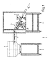
- the device 1 for measuring and sorting workpieces comprises two frames 2, 3, one on a frame 2 Vibration conveyor 4 and on the other frame 3 one Measuring arrangement 5 and a sorting arrangement 6 for measuring and Sorting of the workpieces is built up.
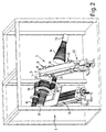
- the measuring arrangement 5 is clearer and in perspective representation recognizable.
- the measuring arrangement 5 comprises a slide rail 8, which consists of two along a vertex line S assembled angle pieces 9, 10, so that there is a V or. L-profile of the slide rail 8 results.
- the slide rail 8 is in two rotatable brackets 11, 12 attached, whereupon below is discussed in more detail.
- a light source 13 with a lens 14 is on one side of the Slide rail 8 arranged.
- On the other side of the slide rail are on a linear feed 15 three cameras 16, 17, 18 with different lenses 19, 20, 21 attached.
- the Linear manipulator 15 is aligned so that the cameras 16, 17, 18 are displaceable parallel to the slide rail 8.
- the slide rail 8 and two outlet rails 23, 24 are off Not shown in full length for reasons of clarity, but at their ends pointing towards the switch 22 cut off.
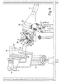
- the light source 13 is in a socket 26 via the lens 14 supported, which is rotatable about an axis of rotation 27 and in the direction of Double arrow P is adjustable in height. Likewise, in not shown the linear feed 15 for the Cameras 16, 17, 18 adjustable.
- the slide rail 8 which via a corresponding bracket 28 (s. Fig. 1) is adjustable with its angle of inclination ⁇ as already indicated above, can be rotated by one to the apex line S parallel axis of rotation.
- the slide rail 8 is in two Sockets 26 mounted, which is a V-profile adapted to the slide rail 8 exhibit.
- the socket 26 encompasses the outer edges 29, 30 of the two angle pieces 9, 10 of the slide rail 8.
- Each socket 26 is attached to a rotating plate 31 which is two curved Has elongated holes 32, 33, the exact fit of two guide rods 34, 35 are interspersed. This results in a rotation guide for the rotating plate 31 in the manner of a backdrop guide.
- Two Stop screws 36, 37 in corresponding holders 38, 39 define in conjunction with one on the rotating plate 31 attached stop 40 two end positions of the rotary plate 31 and thus the slide rail 8.
- the operation of the device 1 according to the invention will not be described in more detail Workpieces shown filled in the vibration conveyor 4. This essentially already promotes these workpieces to the belt conveyor 7.
- the belt conveyor 7 has a larger one Conveying speed than the vibration conveyor 4, so that the recorded workpieces can be spaced further apart.
- Pre-sorting means not shown, for example with a laser curtain for runtime measurement and blow-out nozzles sort the workpieces on the belt conveyor 7 before. Closely workpieces lying together by the runtime measurement as a Workpiece to be measured or workpieces that are in a particular Dimension differ significantly from a specified value and therefore none can represent regular workpieces sorted out. This ensures that only actually measuring workpieces are transported to the slide rail 8.
- the belt conveyor 7 is on the vibration conveyor 4 or its frame 2 attached. Due to the separate frames 2, 3 and Air gap 25 is thus ensured that no vibrations the conveyors 4, 7 transferred to the slide rail 8 can be.
- Rotationally symmetrical workpieces such as turned parts are in one measured the first angular position of the slide rail 8 in which this Workpieces by their own weight on the apex line S Slide rail 8 are drawn. Since such workpieces, for example screws, different along their axis Can have circumferences, is therefore a positioning of the Slide rail 8 possible, in which the axis of the workpiece in the angle bisecting plane mentioned, but is an inclination to the apex line S of the slide rail 8.
- the light source 13 with its lens 14 and each of the cameras 16, 17, 18 used are exact perpendicular to the axis, d. H. perpendicular to the apex line S, the Slide rail 8 arranged. This ensures that the sliding workpieces in the camera 16, 17, 18 in one right-angled projection.
- the slide rail 8 Due to the telecentric design of the lenses 14, 19, 20, 21 the slide rail 8 is always under a parallel beam path screened. This plays the distance between the respective cameras 16, 17, 18 or their objective 19, 20, 21 from the slide rail 8 not matter.
- the slide rail 8 exists at least in the measuring range, i.e. H. by doing Area between the light source 13 and the one used upcoming camera 16, 17, 18 made of transparent material, for example made of glass, with respect to the radiation spectrum of the Light source 13.
- the elbows 9, 10 cross in this Measuring position the beam path of the illumination source 13 so that the Path the corresponding light radiation through the slide rail 8 must pass through, is comparatively small.
- This creates an image in which the workpiece is one has clear contrast to the surrounding slide rail 8. This enables a direct measurement of all described in the Projection shown edges of the workpiece.
- the picture shows a quasi free-floating workpiece.
- the various cameras 16 to 18 are for use with different sized workpieces. It can be the camera 16, 17, 18 with the corresponding front optics 19, 20, 21 selected be the best when the workpiece is fully reproduced Provides resolution. Through the linear manipulator 15 can easily the camera required in each case in the opposite of the light source 13 lying position.
- the detectors listed above, e.g. B. laser curtains, on the one hand to trigger the light source 13 or the camera 16 used, 17, 18 and on the other hand for triggering the switch 22 are in the Figures not shown, but are along the Slide rail 8 arranged.
- a computer 50 for image processing has a monitor 51, a keyboard 52, a mouse 53 and a printer 54.
- the three cameras 16, 17, 18 are also in connection with the image processing system 50.
- Other interfaces, e.g. B. parallel interfaces, serial Interfaces or bus interfaces are with lines 55 indicated.
- the light source 13 is controlled by a controller 56 which also communicates with the image processing system 50, controlled.
- a separate controller 57 works with the Image processing 50 together and controls the signals the other components connected via a distributor 58.
- Such components can be in the form of laser curtains 59, 60, 61 the switch 22, nozzles 62, 63, the vibration conveyor 4 and the Belt conveyor 7 are present.
- a power strip 64 is used for Connection of additional components.
- the controller 57 controls the listed components in the way described and directs the for operation, z. B. to Trigger, necessary signals to the image processing unit 50. This is detected by means of the pulsed via the controller 56 Light source 13 and the selected camera 16, 17 or 18 a Snapshot of the workpiece. After an image evaluation like explained in more detail below, the controller 57 receives the for Sorting necessary information to set the switch 22. If he receives no information or information that is too late, the switch 22 is always set by the controller so that appropriate workpiece is assigned to the committee.
- each Workpiece in slide rail 8 it is possible to go along predetermined Search paths to search for contours of the workpiece that are going through express a light-dark transition in the image.
- a such search path as far as possible perpendicular to one Contour line placed.
- a rough definition of the intersection of the Search path of the contour line or the light / dark transition edge is carried out via a so-called binary image.
- For the production of such a binary image becomes the gray scale value of each pixel that is recorded by the camera, depending on whether the gray value is below or above a predetermined threshold Value for black (e.g. 0) or for white (e.g. 255 in the case of a 8-bit gray gradation).
- 6 is the black and white transition shown within an edge region 70.
- Search path 71 which in the present case is immediately adjacent, as Contains squares drawn pixels, crosses the Transition area 70 or the edge captured thereby.
- the gray value is now three each pixels 73, 74, 75 adjacent to search path 71 are averaged.
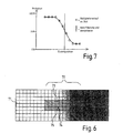
- Fig. 7 shows the brightness profile of gray values averaged in this way in one XY diagram. The squares represent the points recorded of the individual pixels.
- a so-called fit e.g. B.
- a so-called spline fit d. H.
- one or more mathematical functions are optimized to the measured values and interpolate them accordingly.
- the solid line 7 shows such an interpolation with splines.
- the inflection point of the interpolation curve is now considered to be exact Edge position used.
- any number can be used Measure the edge points of the workpiece.
- this is a Coordinate system defined. This is done along the axis of the Slide rail 8 is an edge point of a transverse edge searched. With two essentially perpendicular to the slide rail 8 search paths is then a straight line that is parallel to an actual edge of the workpiece. This straight line results in an axis of the coordinate system searched for. The projection of the previously described point on this straight line results in the second Axis. In this way, a coordinate system is available that usually lies parallel to two contour lines of the workpiece. Those now measured for measuring the workpiece This makes point coordinates particularly easy to find Implement workpiece dimensions.
Landscapes
- Physics & Mathematics (AREA)
- General Physics & Mathematics (AREA)
- Sorting Of Articles (AREA)
- Length Measuring Devices By Optical Means (AREA)
- Electrical Discharge Machining, Electrochemical Machining, And Combined Machining (AREA)
- Multi-Process Working Machines And Systems (AREA)
Abstract
Description
Die Erfindung betrifft eine Vorrichtung zur Vermessung und Sortierung von Werkstücken nach dem Oberbegriff des Anspruchs 1.The invention relates to a device for measuring and Sorting workpieces according to the preamble of claim 1.
Eine solche Vorrichtung ist z.B. aus dem Dokument GB-A-2271846 bekannt.Such a device is e.g. known from document GB-A-2271846.
Werkstücke verschiedenster Art, insbesondere Schrauben, Bolzen und ähnliche Kleinteile, die in großen Mengen hergestellt werden, müssen eine Endkontrolle zur Prüfung der Fertigungsgenauigkeit durchlaufen. Schlechte Teile, d. h. Teile die in ihren Ausmaßen nicht in einem vorgegebenen Intervall von Fertigungstoleranzen liegen, müssen aussortiert werden. Die Hersteller der entsprechenden Werkstücke müssen die Fertigungsqualität garantieren, weshalb möglichst jedes Teil auch einer großen Serie geprüft werden muß.Various types of workpieces, in particular screws, bolts and similar small parts that are manufactured in large quantities, need a final inspection to check manufacturing accuracy run through. Bad parts, i. H. Divide them in their dimensions not in a predetermined interval of manufacturing tolerances must be sorted out. The manufacturers of the corresponding workpieces must have manufacturing quality guarantee why every part of a large series if possible must be checked.
Hierzu sind Vorrichtungen bekannt geworden, bei denen die Werkstücke über eine Fördervorrichtung vor eine Kamera positioniert werden, an die eine Bildauswerteeinheit angeschlossen ist. Der jeweilige Gegenstand wird entsprechend seiner jeweiligen Lage vor der Kamera mit seinen Konturen aufgenommen, so daß entsprechende Maße zwischen den Konturen über die Bildauswerteeinheit erfaßbar sind.For this purpose, devices have become known in which the Workpieces on a conveyor in front of a camera be positioned to which an image evaluation unit is connected is. The particular item will correspond to its respective Position taken in front of the camera with its contours, so that corresponding dimensions between the contours over the Image evaluation unit can be detected.
Die Werkstücke können hierzu im freien Fall vor der Kamera durchfallen, oder aber über eine Gleitschiene geführt werden. Bei der Messung im freien Fall ist eine Positionierung mit definierter Stellung des Werkstücks vor der Kamera nicht möglich, wodurch sich Fehler im Meßergebnis ergeben können.The workpieces can do this in free fall in front of the camera fall through, or be guided over a slide rail. At The measurement in free fall is a positioning with a defined one It is not possible to position the workpiece in front of the camera Errors in the measurement result.
Im Falle einer Gleitschiene bestand bislang der Nachteil, daß der Bereich der Auflage des Werkstücks auf der Gleitschiene nicht als scharfe Kontur zu erfassen war. Das aufliegende Werkstück war nur durch eine sogenannte indirekte Messung mit seiner Auflagekante auf der Gleitschiene zu erfassen, bei der von einem Fixpunkt aus die Gleitschiene mitgemessen und anschließend vom Meßergebnis abgezogen wird.In the case of a slide rail, there was previously the disadvantage that the Area of the support of the workpiece on the slide rail is not as sharp contour was to be recorded. The workpiece lying on was only through a so-called indirect measurement with its contact edge to be recorded on the slide rail at a fixed point measured the slide rail and then from the measurement result is subtracted.
Ein besseres Ergebnis, d. h. ein Ergebnis mit höherer Genauigkeit läßt sich jedoch durch direkte Messung erzielen, wie dies bei freischwebenden Werkstücken der Fall ist, sofern eine definierte Lage des Werkstücks erzielt wird.A better result, i. H. a result with higher accuracy can, however, be achieved by direct measurement, as is the case with free-floating workpieces is the case, provided a defined one Position of the workpiece is achieved.
Aufgabe der Erfindung ist es daher, eine Messvorrichtung vorzuschlagen, bei der einerseits eine definierte Position der Werkstücke erreicht wird und andererseits eine direkte Messung über alle notwendigen Konturenlinien durchgeführt werden kann.The object of the invention is therefore a measuring device to propose, on the one hand, a defined position of the Workpieces is reached and on the other hand a direct measurement can be carried out over all necessary contour lines.
Diese Aufgabe wird ausgehend von einer Vorrichtung der einleitend genannten Art durch die kennzeichnenden Merkmale des Anspruchs 1 gelöst.Starting from a device, this task is initiated mentioned type by the characterizing features of claim 1 solved.
Durch die in den Unteransprüchen genannten Maßnahmen sind vorteilhafte Ausführungen und Weiterbildungen der Erfindung möglich. By the measures mentioned in the subclaims advantageous embodiments and developments of the invention possible.
Dementsprechend zeichnet sich eine erfindungsgemäße Vorrichtung dadurch aus, daß eine Gleitschiene verwendet wird, die wenigstens im Bereich der Werkstückauflage aus transparentem Material in Bezug zum Strahlungsspektrum der für die Beleuchtung der Werkstücke verwendeten Leuchtquelle besteht. Hierdurch ist es möglich, auch die auf der Gleitschiene aufliegenden Kontur unmittelbar über die Kamera zu erfassen und anschließend durch die Bildauswerteeinheit auszumessen. Durch die Gleitschiene wird die gewünschte definierte Position des Werkstücks erzielt, während durch die transparente Ausbildung der Gleitschiene der komplette Außenumfang des Werkstücks einer Bilderfassung zugänglich wird.Accordingly, a device according to the invention is distinguished characterized in that a slide rail is used, which at least in the area of the workpiece support made of transparent material in Reference to the radiation spectrum for the illumination of the Workpieces used light source exists. This is it possible, also the contour resting on the slide rail directly on the camera and then by the Measure the image evaluation unit. Through the slide rail desired defined position of the workpiece is achieved while the complete design thanks to the transparent design of the slide rail Image capture of the outer circumference of the workpiece is accessible.
Vorzugsweise wird als Leuchtquelle eine Infrarotquelle und als Kamera entsprechend eine Infrarot-Kamera verwendet. Dies hat den Vorteil, daß die Beleuchtung und die Bilderfassung unabhängig von den jeweiligen Lichtverhältnissen am Einsatzort der Vorrichtung ist.An infrared source is preferably used as the light source and Camera uses an infrared camera accordingly. This has the Advantage that the lighting and image capture regardless of the respective lighting conditions at the place of use of the device is.
In einer besonderen Ausführungsform kann zusätzlich ein Tageslichtfilter beispielsweise vor dem Objektiv der Kamera verwendet werden, um auch die letzten Störeffekte durch das Tageslicht auszuschalten.In a special embodiment, a Daylight filters, for example, in front of the camera lens used to remove even the last disturbing effects from the Turn off daylight.
In einer besonderen Ausführungsform der Erfindung wird die Gleitschiene wenigstens im Bereich der Werkstückauflage aus Glas gefertigt. Infrarotdurchlässige Glasscheiben sind kostengünstig erhältlich und mit einer ausreichender Planparallelität der Grenzflächen kostengünstig zu erhalten.In a particular embodiment of the invention, the Slide rail at least in the area of the workpiece support made of glass manufactured. Infrared transparent glass panes are inexpensive available and with sufficient plane parallelism of the To get interfaces cheaply.
Die Gleitschiene wird mit einem V- oder L-förmigen Querschnitt ausgebildet. Dies bietet insbesondere bei Drehteilen, die eine Rotationssymmetrie aufweisen, den Vorteil, daß diese sich bei einer geneigten Lage der V-Schiene definiert so in diese Gleitschiene einfügen, daß die Achse der Werkstücke in der winkelhalbierende Ebene der V-Schiene liegt. Weiterhin ist die der Gleitschiene zugewandte Kontur des Werkstücks bei dieser Ausbildung immer ein wenig vom Scheitel des V-Profils erhöht. Das für die Darstellung der Werkstückkontur verwendete Licht muß so nur die vergleichsweise dünne Wand der Gleitschiene queren. Dies ist mit größerer Transmission möglich, als im Bereich des Scheitelpunkts, wo die beiden Winkelstücke aufeinandertreffen. Auf diese Weise kann das Werkstück quasi freischwebend in definierter Lage von der Kamera erfaßt werden.The slide rail is made with a V or L shape Cross section formed. This is particularly useful for turned parts, which have a rotational symmetry, the advantage that they are with an inclined position of the V-rail defined in this Insert slide rail that the axis of the workpieces in the bisecting plane of the V-rail. Furthermore, the Contour of the workpiece facing the slide rail Training always increased a little from the apex of the V-profile. The light used for the representation of the workpiece contour must be so only cross the comparatively thin wall of the slide rail. This is possible with greater transmission than in the area of the Vertex where the two contra-angles meet. On In this way, the workpiece can be made to float in a defined manner Location can be captured by the camera.
Als vorteilhaft hat sich die Verwendung einer drehbaren Schiene erwiesen. Hierdurch ist es möglich, die oben genannten Vorteile bei Drehteilen zu erzielen und andererseits auch Werkstücke mit anderer Geometrie, beispielsweise scheibenartige Werkstücke, vermessen zu können. Für die Drehteile wird die V- oder L-Schiene so gedreht, daß diese auf die Scheitellinie der Drehschiene zugleiten und dort die oben angegebenen definierte Position mit ihrer Achse in der winkelhalbierenden Ebene einnehmen. Für scheibenförmige Teile wird die Gleitschiene soweit gedreht, bis ein Winkelstück des V- bzw. L-Profils eine zuverlässige Auflagefläche für die zu vermessenden Werkstücke bildet. Eine leichte Neigung der Auflagenfläche sorgt hierbei dafür, daß die scheibenartigen Werkstücke zuverlässig soweit in das L- bzw. V- Profil hineingleiten, bis sie an dem zweiten Schenkel des Profils anstoßen. Hierdurch wird ein definierter Abstand zur Kamera vorgegeben.The use of a rotatable rail has proven advantageous proven. This makes it possible to take advantage of the above to achieve with turned parts and on the other hand also with workpieces other geometry, for example disk-like workpieces, to be able to measure. The V or L rail is used for the turned parts rotated so that this on the apex line of the rotating rail slide and there the defined position indicated above take their axis in the bisecting plane. For disc-shaped parts, the slide rail is rotated until an elbow of the V or L profile a reliable Forms the support surface for the workpieces to be measured. A slight inclination of the support surface ensures that the disc-like workpieces reliably so far into the L or V Slide the profile in until it is on the second leg of the profile nudge. This creates a defined distance from the camera given.
Besonders vorteilhaft ist es, die Gleitschiene so anzuordnen, daß bei einem Verdrehen der Gleitschiene die Kamera und die Leuchtquelle fixiert bleiben.It is particularly advantageous to arrange the slide rail so that when the slide rail is turned, the camera and the Light source remain fixed.
In einer besonderen Ausführungsform der Erfindung werden zwei getrennte Fördereinheiten vorgesehen. Eine erste Fördereinheit, die beispielsweise in Form eines Vibrationsförderers ausgebildet sein kann, fördert die zu vermessenden Werkstücke aus einem Vorratsbehälter hierbei mit einer vergleichsweise langsamen Fördergeschwindigkeit. Eine zweite schnellere Fördereinheit, beispielsweise ein Förderband, nimmt die Werkstücke von der langsameren Fördereinheit auf, wodurch sich ein Vereinzelungseffekt ergibt. Durch die Einstellung der jeweiligen Fördergeschwindigkeiten läßt sich der Abstand der einzelnen Werkstücke bestimmen.In a particular embodiment of the invention, two separate conveyor units are provided. A first conveyor unit which, for example, in the form of a vibration conveyor can convey the workpieces to be measured from one Storage container here with a comparatively slow Conveyor speed. A second faster conveyor unit, for example a conveyor belt, takes the workpieces from the slower feed unit on, causing a Separation effect results. By hiring each Conveyor speeds can be the distance of each Determine workpieces.
Bevorzugt wird vor der Gleitschiene ein Vorsortierer vorgesehen. Dieser Vorsortierer kann beispielsweise in Form eines Gebläses im Bereich der zweiten Fördereinheit angebracht werden. Über diesen Vorsortierer können die Werkstücke aufgrund einer groben Vormessung vorsortiert werden. Diese Messung kann beispielsweise in Form einer Laufzeitmessung der Werkstücke geschehen. Hierzu empfiehlt sich ein sogenannter Laservorhang, mit dem die durchlaufenden Werkstücke erfaßt werden können. Sofern die Werkstücke eine sehr stark abweichende Länge oder so dicht aufeinanderfolgen, daß sie als zusammenhängendes Teil erfaßt werden, aufweisen, können Sie von dem Vorsortierer, beispielsweise dem Gebläse von der schnelleren zweiten Fördereinheit entfernt, beispielsweise heruntergeblasen werden. Eine entsprechende Steuerung sorgt für die notwendige Auswertung des Lasersignals sowie die Ansteuerung des Vorsortierers.A pre-sorter is preferably provided in front of the slide rail. This pre-sorter can, for example, in the form of a fan in the Area of the second conveyor unit are attached. About this Pre-sorters can cut the workpieces due to a rough Pre-measurement can be pre-sorted. This measurement can, for example done in the form of a runtime measurement of the workpieces. For this a so-called laser curtain is recommended, with which the continuous workpieces can be detected. If the Workpieces a very different length or so tight successive that they are grasped as a coherent part from the pre-sorter, for example the blower is removed from the faster second conveyor unit, for example, be blown down. A corresponding Control ensures the necessary evaluation of the laser signal as well as the control of the pre-sorter.
In einer vorteilhaften Ausführungsform wird zusätzlich eine kontinuierliche betriebene Düse vorgesehen, um kleinere Fremdkörper wie Späne oder sonstige Verunreinigungen vor dem Erreichen der Gleitschiene auszublasen. Auf diese Weise bleibt die transparente Gleitschiene von den Verunreinigungen geschützt.In an advantageous embodiment, a continuously operated nozzle provided to smaller Foreign bodies such as chips or other contaminants before Blow out when reaching the slide rail. In this way it stays transparent slide rail protected from contamination.
Der Übergang von den Fördereinrichtungen auf die Gleitschiene wird bevorzugt über einen Luftspalt durchgeführt, so daß die Gleitschiene von sämtlichen Vibrationen und sonstigen Störbewegungen der Fördereinheiten nicht beeinträchtigt wird.The transition from the conveyor to the slide will be preferably carried out over an air gap, so that the Slide from all vibrations and other Interfering movements of the conveyor units are not affected.
Die Präzision der Messungen läßt sich dadurch verbessern, daß durch eine möglichst kurze Momentaufnahme unabhängig von der Gleitbewegung der Werkstücke das Bild erfaßt wird. Eine derartige Momentaufnahme kann zum einen über eine entsprechend gepulst betriebene Kamera bewerkstelligt werden. In einer vorteilhaften Ausführungsform empfiehlt sich zusätzlich der Einsatz einer gepulsten Leuchtquelle. Für die Zeitdauer der Momentaufnahme ist somit das jeweils kürzere Zeitsignal, entweder für die gepulste Leuchtquelle oder aber für die gepulst betriebene Kamera ausschlaggebend.The precision of the measurements can be improved in that by making the snapshot as short as possible regardless of the Sliding movement of the workpieces the image is captured. Such On the one hand, snapshot can be pulsed accordingly operated camera can be accomplished. In an advantageous Embodiment also recommends the use of a pulsed light source. For the duration of the snapshot is thus the shorter time signal, either for the pulsed one Light source or for the pulsed camera decisive.
Für den Impulsbetrieb sowohl der Leuchtquelle als auch der Kamera ist ein Triggersignal notwendig, das vorzugsweise über einen Detektor ausgelöst wird, der im Bezug zur Gleitrichtung vor der Kamera an der Gleitschiene montiert ist. Als Detektor hat sich hier ein weiterer Laservorhang als Trigger für die Leuchtquelle und/oder die Kamera bewährt.For the pulse operation of both the light source and the camera a trigger signal is necessary, preferably via a Detector is triggered, which is in relation to the sliding direction in front of the Camera is mounted on the slide rail. As a detector here another laser curtain as a trigger for the light source and / or the camera has proven itself.
Vorteilhafterweise wird nach der Bilderfassung des Werkstücks am Ende der Gleitschiene eine Auslaufschiene mit Weiche vorgesehen. Über die Weiche kann das Werkstück in entsprechende Behälter sortiert werden. Hierzu sind wenigstens zwei Behälter vorzusehen, die von der Weiche ansteuerbar sind. Im Falle von lediglich zwei Sortierbehältern werden in einen Behälter die als gut befundenen Teile und in den anderen Behälter die Ausschußware geleitet. Denkbar wäre auch eine Sortierung in verschiedene Bereiche von Fertigungstoleranzen, die entsprechende Güteklassen der Werkstücke definieren können.Advantageously, after the image capture of the workpiece An outlet rail with a switch is provided at the end of the slide rail. The workpiece can be placed in appropriate containers via the switch be sorted. For this purpose, at least two containers are to be provided, which can be controlled by the switch. In the case of only two Sorting containers are placed in a container which is found to be good Parts and in the other container the rejects passed. Sorting into different areas of would also be conceivable Manufacturing tolerances, the corresponding quality classes of the workpieces can define.
Die Auslaufschiene wird wiederum bevorzugt nicht unmittelbar mit der Gleitschiene verbunden, sondern übernimmt die Werkstücke über einen kleinen Luftspalt. Hierdurch bleibt die Gleitschiene von Erschütterungen, die durch das Betätigen der Weiche ausgelöst werden können, verschont.The outlet rail is in turn preferably not directly included connected to the slide rail, but takes over the workpieces a small air gap. This keeps the slide from Shocks triggered by operating the switch can be spared.
Die Weiche kann mit verschiedenen Antriebssystemen versehen sein. Im Einsatz bewährt hat sich eine Weiche mit elektrischem Antrieb. Hierbei empfiehlt sich der Einsatz einer elektronischen Steuerung, die Überspannungspulse oberhalb der Nennspannung der Weiche erzeugen kann. Durch derartige Überspannungspulse wird die Weiche schneller, wobei durch die kurzzeitige Belastung aufgrund der Zeitverteilung der Pulse ein Defekt durch Überbelastung ausgeschlossen wird.The switch can be provided with different drive systems. A switch with an electric drive has proven itself in use. The use of an electronic control is recommended here the overvoltage pulses above the nominal voltage of the switch can generate. The switch is made by such overvoltage pulses faster, due to the short-term exposure due to the Time distribution of the pulses is a defect due to overload is excluded.
In einer besonders vorteilhaften Ausführungsform wird ein zusätzlicher Detektor, beispielsweise ein weiterer Laservorhang als Trigger für die Weiche vorgesehen. Hiermit kann die Weiche so gesteuert werden, daß Teile, die im Bereich der Weiche ankommen und noch nicht ausgewertet sind, stets der Ausschußware zugeordnet werden. Bevorzugt wird hierbei die Standardeinstellung der Weiche so gewählt, daß diese ankommende Ware als Ausschußware sortiert. Nur in einem bestimmten Zeitintervall ab dem genannten Triggersignal wird die Umschaltung der Weiche aufgrund positiver Bildauswertung zugelassen.In a particularly advantageous embodiment, a additional detector, for example another laser curtain intended as a trigger for the switch. With this the switch can do so controlled that parts that arrive in the area of the switch and are not yet evaluated, always assigned to the rejects become. The standard setting of the switch is preferred chosen so that these incoming goods are sorted as rejects. Only in a certain time interval from the above The switch signal is triggered by a positive signal Image evaluation allowed.
In einer weiteren besonderen Ausführungsform werden mehrere Kameras vorzugsweise über einen Linearmanipulator verschiebbar, angeordnet. Durch die Verwendung mehrerer Kameras, die vor allem unterschiedliche Objektive aufweisen können, ist es möglich, mit einer Vorrichtung unterschiedlichste Werkstücke verschiedener Größenordnungen zu vermessen und dabei stets eine möglichst hohe Meßgenauigkeit zu gewährleisten. Durch die verschiebbare Ausführung der verschiedenen Kameras entfällt eine aufwendige Justage beim Umschalten auf eine andere Kamera.In a further special embodiment, several Cameras can preferably be moved using a linear manipulator, arranged. By using multiple cameras, most of all can have different lenses, it is possible with one piece of different workpieces different Orders of magnitude and always the highest possible To ensure measurement accuracy. By the sliding Execution of the different cameras eliminates a complex Adjustment when switching to another camera.
Bevorzugt wird die optische Anordnung der Leuchtquelle und der jeweiligen Kamera telezentrisch ausgebildet. Dies bedeutet, daß die von der Leuchtquelle bzw. deren Objektiv austretenden Strahlen einen zur optischen Achse parallelen Strahlengang aufweisen. Aufgrund der bereits oben angedeuteten Planparallelität der einzelnen Schenkel der Meßschiene bleibt dieser parallele Strahlengang beim Durchtritt durch das transparente Medium erhalten.The optical arrangement of the light source and the respective camera telecentrically trained. This means that the rays emerging from the light source or its lens have a beam path parallel to the optical axis. Due to the plane parallelism of the individual leg of the measuring rail remains parallel Beam path when passing through the transparent medium receive.
Die Werkstücke werden bevorzugt so angeordnet (durch entsprechende Ausrichtung der Gleitschiene), daß die zu vermessenden Strecken senkrecht zu dem parallelen Strahlenbündel der Leuchtquelle liegen, so daß die gewünschten Werkstückkonturen erfaßt werden. Die Kamera bildet dieses parallele Strahlenbündel anschließend auf seinen Detektor, zum Beispiel einen Diodenarray ab. Durch die telezentrische Ausbildung der Optik spielt der Abstand des Werkstücks von der Kamera keine Rolle mehr.The workpieces are preferably arranged in this way (by appropriate Alignment of the slide rail) that the distances to be measured perpendicular to the parallel beam of the light source lie so that the desired workpiece contours are detected. The camera then forms this parallel beam its detector, for example a diode array. Through the telecentric training of the optics plays the distance of the Workpiece from the camera no longer matters.
In einer besonders vorteilhaften Ausführungsform werden in der Bildauswerteeinheit Mittel zur Verbesserung der Meßgenauigkeit über die Auflösung der Kamera hinaus vorgesehen.In a particularly advantageous embodiment, the Image evaluation unit Means for improving the measuring accuracy beyond the resolution of the camera.
Diese Mittel zur Verbesserung der Meßgenauigkeit umfassen in einer besonderen Ausführungsform eine Vorauswahl eines Suchpfads über eine zu vermessende Konturenlinie, die in einem Diagramm der gemessenen Grauwerte entlang des Suchpfades als Kante erscheint, innerhalb eines sogenannten Binärbildes. Ein solches Binärbild kommt dadurch zustande, daß ein bestimmter Schwellenwert für den Grauwert jedes Pixels des Kamerabilds bestimmt wird, wobei der Wert 0 (schwarz) bzw. der Wert 255 (weiß) gesetzt wird, je nach dem ob der tatsächliche Grauwert des Pixels unterhalb oder oberhalb des Schwellenwertes liegt. Durch ein derartiges Binärbild können die zu vermessenden Punkte einer Kontur bzw. die Kanten grob erfaßt werden.These means for improving the measuring accuracy include in one special embodiment a preselection of a search path via a contour line to be measured, which is shown in a diagram of the measured gray values along the search path appear as an edge, within a so-called binary image. Such a binary image comes about because a certain threshold for the Gray value of each pixel of the camera image is determined, the Value 0 (black) or value 255 (white) is set, depending on whether the actual gray value of the pixel below or is above the threshold. With such a binary image can measure the points of a contour or the edges be roughly grasped.
In einer weiteren vorteilhaften Ausführungsform werden sodann die Grauwerte benachbarter Pixel, beispielsweise dreier benachbarter Pixel entlang dem Suchpfad gemittelt. Falls der Suchpfad treppenartig ist, was unter Umständen aufgrund eines bezüglich der Matrixanordnung eines Diodenarrays der Kamera schrägen Verlaufs der Fall ist, können die einzelnen Grauwerte bei der Mittelwertbildung zudem gewichtet werden.In a further advantageous embodiment, the Gray values of neighboring pixels, for example three neighboring ones Pixel averaged along the search path. If the search path is stepped, which may be due to a Matrix arrangement of a diode array of the camera oblique course the case is, the individual gray values in the Averaging can also be weighted.
Vorzugsweise wird die exakte Lage der Kante sodann dadurch herausgefunden, indem eine oder mehrere mathematische Funktionen, beispielsweise Splines über die gefundenen Grauwerte angepaßt wird bzw. diese interpolieren und der Wendepunkt dieser Interpotationskurve einen Punkt an der Kontur des Werkstücks definiert.The exact position of the edge is then preferably thereby found out by using one or more math functions, For example, splines are adjusted using the gray values found or interpolate them and the turning point of them Interpotation curve a point on the contour of the workpiece Are defined.
Vorteilhafterweise wird ein Koordinatensystem, innerhalb dem Meßpunkte wie oben angeführt bestimmt werden, parallel zu zwei rechtwinklig zueinanderstehenden Konturenlinien des Werkstücks festgelegt. Bevorzugt wird hierbei nach der oben genannten Methode ein Konturenpunkt entlang einer sogenannten Fanglinie parallel zur Gleitschiene und zwei Konturenpunkte entlang zweier Fanglinien, die ungefähr die gewünschte Konturenlinie des Werkstücks queren, gesucht. Durch die definierte Position des Werkstücks in der Gleitschiene kann eine derartige Auswertung eingestellt werden. Durch zwei Punkte auf einer gewünschten und gefundenen Konturenlinie läßt sich die erste Koordinatenachse als gerade Fortsetzung dieser Konturenlinie finden, wobei sich die zweite Achse des Koordinatensystems durch das Lot des einen Punktes, der parallel zur Gleitschiene gesucht wurde, auf die erste Achse ergibt.A coordinate system within which Measuring points can be determined as stated above, parallel to two Contour lines of the workpiece that are at right angles to one another fixed. Preference is given to the above method a contour point along a so-called snap line parallel to Slide rail and two contour points along two snap lines, which roughly cross the desired contour line of the workpiece, searched. Due to the defined position of the workpiece in the Such an evaluation can be set for the slide rail. By two points on a desired and found Contour line can be the first coordinate axis as straight Find continuation of this contour line, with the second Axis of the coordinate system through the plumb of one point, the parallel to the slide rail was searched on the first axis results.
Innerhalb eines einmal, beispielsweise auf die geschilderte Weise festgelegten Koordinatensystems, dessen Achsen wie erwähnt zwei rechtwinklig zueinander verlaufenden Konturenlinien des Werkstücks folgen, werden sodann alle weiteren Meßpunkte bestimmt.Within one time, for example in the manner described specified coordinate system, whose axes as mentioned two Contour lines of the workpiece running at right angles to one another follow, all further measuring points are then determined.
Je nach Werkstück und Form der Gleitschiene sind verschiedene fest vorgegebene Positionen der Werkstücke auf der Gleitschiene möglich. Bei einem Drehteil in einer V- oder L-Schiene sind beispielsweise zwei Ausrichtungen möglich, in der die Achse des Drehteils auf der winkelhalbierenden Ebene der Schiene liegt und das Werkstück in der Schiene aufliegt. Um hier unterschiedliche, jedoch fest definierte Positionen zuzulassen und gute Werkstücke dennoch herauszufinden, wird in einer bevorzugten Ausführungsform so vorgegangen, daß die mehrere Auswertungen des Bildes stattfinden, wobei jeweils von einer möglichen Ausrichtung des Werkstücks ausgegangen wird. Sofern auch nur bei einer Auswertung ein korrektes Meßergebnis geliefert wird, kann das Werkstück sodann als gutes Teil sortiert werden, da diese Auswertung der tatsächlichen Lage des Werkstücks innerhalb der Gleitschiene vor der Kamera entspricht.Depending on the workpiece and shape of the slide rail, various are fixed specified positions of the workpieces on the slide rail possible. With a turned part in a V or L rail For example, two orientations are possible in which the axis of the Turned part lies on the bisecting plane of the rail and the workpiece rests in the rail. To different here however, allow fixed positions and good workpieces Finding out nevertheless is in a preferred embodiment proceeded so that the multiple evaluations of the image take place, each of a possible orientation of the Workpiece is assumed. If only with an evaluation The workpiece can be supplied with a correct measurement result then sorted as a good part, since this evaluation of the actual position of the workpiece within the slide rail corresponds to the camera.
Die Kalibrierung des beschriebenen Meßsystems wird vorteilhafterweise durch Eichenkörper vorgenommen, die entsprechend präzisise vorgefertigt und geprüft sind.The calibration of the measuring system described is advantageously made by oak body that are prepared and checked accordingly precisely.
Ein Ausführungsbeispiel der Erfindung ist in der Zeichnung dargestellt und wird anhand der nachfolgenden Beschreibung näher erläutert.An embodiment of the invention is in the drawing is shown and is described in more detail in the following description explained.
Im einzelnen zeigen
- Fig. 1
- eine schematische Seitenansicht der erfindungsgemäßen Vorrichtung,
- Fig. 2
- eine perspektivische Darstellung der aus Leuchtquelle, Gleitschiene und mehreren Kameras bestehenden Anordnung,
- Fig. 3
- eine Draufsicht auf eine Vorrichtung gemäß Fig. 1,
- Fig. 4
- einen Querschnitt durch eine Anordnung gemäß Fig. 2,
- Fig. 5
- ein Blockdiagramm der Bildauswerteeinheit und der Steuereinheit,
- Fig. 6
- ein Diagramm zur Veranschaulichung der Kantensuche und
- Fig. 7
- ein Diagramm zur Veranschaulichung der endgültigen Bestimmung eines Kantenpunktes.
- Fig. 1
- a schematic side view of the device according to the invention,
- Fig. 2
- 1 shows a perspective representation of the arrangement consisting of light source, slide rail and several cameras,
- Fig. 3
- 2 shows a plan view of a device according to FIG. 1,
- Fig. 4
- 3 shows a cross section through an arrangement according to FIG. 2,
- Fig. 5
- 1 shows a block diagram of the image evaluation unit and the control unit,
- Fig. 6
- a diagram to illustrate the edge search and
- Fig. 7
- a diagram illustrating the final determination of an edge point.
Die Vorrichtung 1 zur Vermessung und Sortierung von Werkstücken
umfaßt zwei Gestelle 2, 3, wobei auf einem Gestell 2 ein
Vibrationsförderer 4 und auf dem anderen Gestell 3 eine
Meßanordnung 5 sowie eine Sortieranordnung 6 zur Vermessung und
Sortierung der Werkstücke aufgebaut ist.The device 1 for measuring and sorting workpieces
comprises two
Zwischen dem Vibrationsförderer 4 und der Meßanordnung 5 befindet
sich ein Bandförderer 7.Is located between the
In Fig. 2 ist die Meßanordnung 5 deutlicher und in
perspektivischer Darstellung erkennbar. Die Meßanordnung 5 umfaßt
eine Gleitschiene 8, die aus zwei entlang einer Scheitellinie S
zusammengefügten Winkelstücken 9, 10 besteht, so daß sich ein V-bzw.
L-Profil der Gleitschiene 8 ergibt. Die Gleitschiene 8 ist in
zwei drehbaren Halterungen 11, 12 befestigt, worauf weiter unten
näher eingegangen wird.2, the measuring
Eine Leuchtquelle 13 mit einem Objektiv 14 ist an einer Seite der
Gleitschiene 8 angeordnet. Auf der anderen Seite der Gleitschiene
sind an einem Linearvorschub 15 drei Kameras 16, 17, 18 mit
unterschiedlichen Objektiven 19, 20, 21 befestigt. Der
Linearmanipulator 15 ist so ausgerichtet, daß die Kameras 16, 17,
18 parallel zur Gleitschiene 8 verschiebbar sind.A
Die Gleitschiene 8 sowie zwei Auslaufschienen 23, 24 sind aus
Gründen der Übersichtlichkeit nicht in voller Länge dargestellt,
sondern an ihren jeweils zur Weiche 22 hinweisenden Enden
abgeschnitten.The
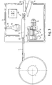
Deutlich zu erkennen ist in Fig. 3, daß die Gleitschiene 8 keinen
Kontakt zum Bandförderer 7 aufweist, da sich ein kleiner Luftspalt
25 zwischen dem Bandförderer 7 und der Gleitschiene 8 befindet.It can be clearly seen in FIG. 3 that the
Die Leuchtquelle 13 ist über das Objektiv 14 in einer Fassung 26
gehaltert, die um eine Drehachse 27 drehbar und in Richtung des
Doppelpfeils P in der Höhe justierbar ist. Ebenso ist auch in
nicht näher dargestellter Weise der Linearvorschub 15 für die
Kameras 16, 17, 18 einstellbar.The
Die Gleitschiene 8, die über eine entsprechende Halterung 28 (s.
Fig. 1) mit ihrem Neigungswinkel α verstellbar ist, ist
wie oben bereits angedeutet drehbar um eine zur Scheitellinie S
parallele Drehachse. Hierzu ist die Gleitschiene 8 in zwei
Fassungen 26 gelagert, die ein der Gleitschiene 8 angepaßtes V-Profil
aufweisen. Die Fassung 26 umgreift die äußeren Ränder 29,
30 der beiden Winkelstücke 9, 10 der Gleitschiene 8. Jede Fassung
26 ist an einer Drehplatte 31 befestigt, die zwei gekrümmte
Langlöcher 32, 33 aufweist, die paßgenau von zwei Führungsstäben
34, 35 durchsetzt sind. Hierdurch ergibt sich eine Drehführung für
die Drehplatte 31 nach Art einer Kulissenführung. Zwei
Anschlagschrauben 36, 37 in entsprechenden Halterungen 38, 39
definieren in Verbindung mit einem an der Drehplatte 31
befestigten Anschlag 40 zwei Endpositionen der Drehplatte 31 und
somit der Gleitschiene 8.The
Im Betrieb der erfindungsgemäßen Vorrichtung 1 werden nicht näher
dargestellte Werkstücke in den Vibrationsförderer 4 gefüllt.
Dieser fördert diese Werkstücke im wesentlichen bereits vereinzelt
zum Bandförderer 7. Der Bandförderer 7 weist eine größere
Fördergeschwindigkeit als der Vibrationsförderer 4 auf, so daß die
aufgenommenen Werkstücke weiter voneinander beabstandet werden.
Nicht näher dargestellte Mittel zur Vorsortierung, zum Beispiel
mit einem Laservorhang zur Laufzeitmessung sowie Ausblasdüsen
sortieren die Werkstücke auf dem Bandförderer 7 vor. Eng
zusammenliegende Werkstücke, die durch die Laufzeitmessung als ein
Werkstück gemessen werden oder Werkstücke, die in einem bestimmten
Maß deutlich von einem vorgegebenen Wert abweichen und somit keine
regulären Werkstücke darstellen können, werden dadurch
aussortiert. Hierdurch ist sichergestellt, daß nur tatsächlich zu
vermessende Werkstücke zur Gleitschiene 8 transportiert werden. The operation of the device 1 according to the invention will not be described in more detail
Workpieces shown filled in the
Weiterhin ist vor der Gleitschiene 8 bevorzugt, wie oben
angeführt, eine Düse angeordnet, um durch Ausblasen leichte
Gegenstände, wie Späne und sonstige Verunreinigungen abzutrennen.
Der Bandförderer 7 ist am Vibrationsförderer 4 bzw. dessen Gestell
2 befestigt. Durch die getrennnten Gestelle 2, 3 sowie den
Luftspalt 25 ist somit sichergestellt, daß keine Erschütterungen
der Fördervorrichtungen 4, 7 auf die Gleitschiene 8 übertragen
werden können.Furthermore, it is preferred in front of the
Rotationssymmetrische Werkstücke wie Drehteile werden in einer
ersten Winkelstellung der Gleitschiene 8 gemessen, in der diese
Werkstücke durch ihr Eigengewicht auf die Scheitellinie S der
Gleitschiene 8 hingezogen werden. Da derartige Werkstücke,
beispielsweise Schrauben, entlang ihrer Achse unterschiedliche
Umfänge aufweisen können, ist somit eine Positionierung der
Gleitschiene 8 möglich, bei der die Achse des Werkstücks zwar in
der genannten winkelhalbierenden Ebene liegt, jedoch eine Neigung
zur Scheitellinie S der Gleitschiene 8 aufweist. Im Falle zweier
unterschiedlicher Umfänge der Werkstücke entlang ihrer Achse,
beispielsweise bei Schrauben mit einem Gewindeabschnitt und einem
Schraubenkopf, sind hierduch genau zwei definierte Lagen in der
Gleitschiene 8 vorgegeben (in Bezug zur Gleitrichtung steht
entweder der Schraubenkopf oder der Gewindeabschnitt nach vorne).Rotationally symmetrical workpieces such as turned parts are in one
measured the first angular position of the
Die Leuchtquelle 13 mit ihrem Objektiv 14 sowie die jeweils von
den Kameras 16, 17, 18 zum Einsatz kommende Kamera sind exakt
senkrecht zur Achse, d. h. senkrecht zur Scheitellinie S, der
Gleitschiene 8 angeordnet. Hierdurch ist sichergestellt, daß die
durchgleitenden Werkstücke in der Kamera 16, 17, 18 in einer
rechtwinkligen Projektion abgebildet werden.The
Durch die telezentrische Ausbildung der Objektive 14, 19, 20, 21
wird die Gleitschiene 8 stets unter parallelem Strahlengang
durchleuchtet. Hierdurch spielt der Abstand der jeweiligen Kamera
16, 17, 18 bzw. deren Objektiv 19, 20, 21 von der Gleitschiene 8
keine Rolle. Due to the telecentric design of the
Die Gleitschiene 8 besteht zumindest im Meßbereich, d. h. in dem
Bereich zwischen der Leuchtquelle 13 und der jeweils zum Einsatz
kommenden Kamera 16, 17, 18 aus transparentem Material,
beispielsweise aus Glas, bezüglich des Strahlungsspektrums der
Leuchtquelle 13. Die Winkelstücke 9, 10 queren in dieser
Meßposition den Strahlengang der Beleuchtungsquelle 13 so, daß der
Weg, den die entsprechende Lichtstrahlung durch die Gleitschiene 8
hindurchtreten muß, vergleichsweise klein ist. Durch das
entsprechend hohe Transmissionsvermögen des ausgewählten Materials
entsteht hierdurch eine Bildaufnahme, in der das Werkstück einen
deutlichen Kontrast zur umgebenden Gleitschiene 8 aufweist. Dies
ermöglicht eine direkte Messung aller in der beschriebenen
Projektion abgebildeten Kanten des Werkstücks. Das Bild zeigt ein
quasi freischwebendes Werkstück.The
Im Falle scheibenartiger Werkstücke ist eine Messung notwendig,
bei der eine flache Seite des Werkstücks auf dem Winkelstück 9
flach aufliegt. Hierzu wird die Gleitschiene 8 soweit gedreht, bis
die Ebene des Winkelstücks 9 parallel zu den Achsen der
Leuchtquelle 13 bzw. der jeweils eingesetzten Kamera 16, 17, 18
liegt. Hierdurch wird eine seitliche Projektion des Werkstücks
abgebildet. Die Anordnung der optischen Achsen ist so gewählt, daß
bei einer derartigen Ausrichtung der Gleitschiene 8 das
Winkelstück 9 eine schwache Neigung aufweist, so daß das Werkstück
in Richtung zum inneren Scheitelpunkt SI gleitet und am anderen
Winkelstück 10 anstößt.In the case of disc-like workpieces, a measurement is necessary
with a flat side of the workpiece on the angle piece 9
lies flat. For this purpose, the
Die verschiedenen Kameras 16 bis 18 sind für den Einsatz bei
verschieden großen Werkstücken gedacht. Es kann jeweils die Kamera
16, 17, 18 mit der entsprechenden Vorsatzoptik 19, 20, 21 gewählt
werden, die bei vollständiger Abbildung des Werkstücks die beste
Auflösung bietet. Durch den Linearmanipulator 15 kann problemlos
die jeweils benötigte Kamera in die gegenüber der Leuchtquelle 13
liegende Position verfahren werden. The
Die oben angeführten Detektoren, z. B. Laservorhänge, einerseits
zum Triggern der Leuchtquelle 13 bzw. der eingesetzten Kamera 16,
17, 18 und andererseits zum Triggern der Weiche 22 sind in den
Figuren nicht näher dargestellt, sind jedoch entlang der
Gleitschiene 8 angeordnet.The detectors listed above, e.g. B. laser curtains, on the one hand
to trigger the
Je nach Stellung der Weiche 22, die im übrigen zur Vermeidung von
Erschütterungen ebenfalls mit der Gleitschiene 8 in Berührung
steht, wird das Werkstück auf die Auslaufschiene 23 oder auf die
Auslaufschiene 24 geleitet. Am Ende dieser Auslaufschienen 23, 24
werden nicht näher dargestellte Auffangbehälter angebracht. Einer
dieser Behälter sammelt demnach für gut befundene Werkstücke,
während in dem anderen Behälter der Ausschuß abgelegt wird.Depending on the position of the
Die Bildauswertung und die Steuerung der Vorrichtung 1 wird anhand
von Fig. 5 beschrieben. Ein Rechner 50 zur Bildverarbeitung
verfügt über einen Monitor 51, eine Tastatur 52, eine Maus 53
sowie einen Drucker 54. Die drei Kameras 16, 17, 18 stehen
ebenfalls mit der Bildverarbeitungssystem 50 in Verbindung.
Weitere Schnittstellen, z. B. parallele Schnittstellen, serielle
Schnittstellen oder Busschnittstellen sind mit den Linien 55
angedeutet. Die Leuchtquelle 13 wird von einer Steuerung 56, die
ebenfalls mit dem Bildverarbeitungssystem 50 kommuniziert,
gesteuert. Ein separater Controller 57 arbeitet mit der
Bildverarbeitung 50 zusammen und steuert bzw. erfaßt die Signale
der weiteren über einen Verteiler 58 zugeschalteten Komponenten.
Derartige Komponenten können in Form von Laservorhängen 59, 60, 61
der Weiche 22, Düsen 62, 63, dem Vibrationsförderer 4 sowie dem
Bandförderer 7 vorliegen. Eine Steckdosenleiste 64 dient zum
Anschluß weiterer Komponenten.The image evaluation and the control of the device 1 is based on
5. A
Der Controller 57 steuert die aufgezählten Komponenten in der
vorbeschriebenen Weise und leitet die für den Betrieb, z. B. zum
Triggern, notwendigen Signale an die Bildverarbeitungseinheit 50.
Diese erfaßt mittels der über die Steuerung 56 gepulsten
Lichtquelle 13 und die ausgewählte Kamera 16, 17 oder 18 eine
Momentaufnahme des Werkstücks. Nach einer Bildauswertung wie
weiter unten näher erläutert erhält der Controller 57 die für die
Sortierung notwendige Information zum Stellen der Weiche 22.
Sofern er keine Information oder eine zu späte Information erhält,
wird die Weiche 22 vom Controller immer so gestellt, daß das
entsprechende Werkstück dem Ausschuß zugeordnet wird.The
Aufgrund der fest definierten, möglichen Positionen jedes
Werkstücks in Gleitschiene 8 ist es möglich, entlang vorgegebener
Suchpfade nach Konturen des Werkstücks zu suchen, die sich durch
einen Hell-Dunkel-Übergang im Bild äußern. Vorzugsweise wird ein
derartiger Suchpfad so weit als möglich senkrecht zu einer
Konturenlinie gelegt. Eine grobe Festlegung des Schnittpunktes des
Suchpfads der Konturenlinie bzw. der hell/dunkel Übergangskante
wird über ein sogenanntes Binärbild durchgeführt. Zur Herstellung
eines derartigen Binärbildes wird dem Grauwert jedes Pixels, das
von der Kamera aufgenommen wird, je nachdem, ob der Grauwert
unterhalb oder oberhalb einer vorgegebenen Schwelle liegt, ein
Wert für schwarz (z. B. 0) oder für weiß (z. B. 255 im Falle einer
8-Bit-Grauabstufung) zugeordnet.Because of the clearly defined, possible positions of each
Workpiece in
Anschließend wird die genaue Kantenposition wie nachfolgend anhand
der Fig. 6 und 7 beschrieben gesucht. In Fig. 6 ist der Schwarz-Weiß-Übergang
innerhalb eines Kantenbereichs 70 dargestellt. Ein
Suchpfad 71, der im vorliegenden Fall unmittelbar benachbarte, als
Quadrate eingezeichnete Pixel beinhaltet, quert den
Übergangsbereich 70 bzw. die dadurch erfaßte Kante.Then the exact edge position is as shown below
6 and 7 described. 6 is the black and white transition
shown within an
Im Übergangsbereich 70 wird nun der Grauwert jeweils dreier quer
zum Suchpfad 71 benachbarter Pixel 73, 74, 75 gemittelt. Fig. 7
zeigt den Helligkeitsverlauf derart gemittelter Grauwerte in einem
XY-Diagramm. Die Quadrate stellen hierbei die aufgenommenen Punkte
der einzelnen Pixel dar. In the
Zur genaueren Auswertung wird nunmehr ein sogenannter Fit, z. B.
ein sogenannter Splinefit, durchgeführt, d. h. eine oder mehrere
mathematische Funktionen werden optimiert an die Meßwerte angepaßt
und interpolieren diese dementsprechend. Die durchgezogene Linie
gemäß Fig. 7 zeigt eine derartige Interpolation mit Splines. Der
Wendepunkt der Interpolationskurve wird nun als exakte
Kantenposition verwendet. Durch das genannte Auswerteverfahren ist
es möglich, eine Genauigkeit zu erzielen, die über das
Auflösungsvermögen der Kamera hinausgeht.For a more precise evaluation, a so-called fit, e.g. B.
a so-called spline fit, d. H. one or more
mathematical functions are optimized to the measured values
and interpolate them accordingly. The
Mit der dargestellten Methode lassen sich beliebig viele
Kantenpunkte des Werkstücks messen. Vorab wird hierzu ein
Koordinatensystem definiert. Hierzu wird entlang der Achse der
Gleitschiene 8 ein Kantenpunkt einer quer hierzu stehenden Kante
gesucht. Mit zwei im wesentlichen senkrecht zur Gleitschiene 8
stehenden Suchpfaden wird sodann eine Gerade erfaßt, die parallel
zu einer tatsächlichen Kante des Werkstücks liegt. Diese Gerade
ergibt eine Achse des gesuchten Koordinatensystems. Die Projektion
des vorbeschriebenen Punktes auf diese Gerade ergibt die zweite
Achse. Auf diese Weise ist ein Koordinatensystem erhältlich, das
in der Regel parallel zu zwei Konturenlinien des Werkstücks liegt.
Die nun im folgenden zur Vermessung des Werkstücks ausgemessenen
Punktkoordinaten sind hierdurch besonders einfach in die gesuchten
Werkstückmaße umzusetzen.With the method shown, any number can be used
Measure the edge points of the workpiece. In advance, this is a
Coordinate system defined. This is done along the axis of the
Eine Weiterentwicklung der oben beschriebenen Kantensuche besteht darin, daß bei der Mittelung über benachbarte Pixel 73, 74, 75 eine Gewichtung vorgenommen wird. Dies ist dann von Vorteil, wenn der Suchpfad 71 nicht parallel zum Raster der Spalten und Reihen der Kamera verläuft, sondern hierzu querliegt und dementsprechend eine mehr oder weniger abgestufte Form aufweist.
- 1
- Vorrichtung
- 2
- Gestell
- 3
- Gestell
- 4
- Vibrationsförderer
- 5
- Meßanordnung
- 6
- Sortieranordnung
- 7
- Bandförderer
- 8
- Gleitschiene
- 9
- Winkelstück
- 10
- Winkelstück
- 11
- Halterung
- 12
- Halterung
- 13
- Leuchtquelle
- 14
- Objektiv
- 15
- Linearvorschub
- 16
- Ramera
- 17
- Kamera
- 18
- Kamera
- 19
- Objektiv
- 20
- Objektiv
- 21
- Objektiv
- 22
- Weiche
- 23
- Auslaufschiene
- 24
- Auslaufschiene
- 25
- Luftspalt
- 26
- Fassung
- 27
- Drehachse
- 28
- Halterung
- 29
- Rand
- 30
- Rand
- 31
- Drehplatte
- 32
- Langloch
- 33
- Langloch
- 34
- Führungsstab
- 35
- Führungsstab
- 36
- Anschlagschraube
- 37
- Anschlagschraube
- 38
- Halterung
- 39
- Halterung
- 50
- Rechner
- 51
- Monitor
- 52
- Tastatur
- 53
- Maus
- 54
- Drucker
- 55
- Schnittstellen
- 56
- Steuerung
- 57
- Controller
- 58
- Verteiler
- 59
- Laservorhang
- 60
- Laservorhang
- 61
- Laservorhang
- 62
- Düse
- 63
- Düse
- 64
- Steckdosenleiste
- 70
- Übergangsbereich
- 71
- Suchpfad
- 72
- Pixel des Suchpfads
- 73
- Pixel
- 74
- Pixel
- 75
- Pixel
- 1
- contraption
- 2
- frame
- 3rd
- frame
- 4th
- Vibratory feeder
- 5
- Measuring arrangement
- 6
- Sorting arrangement
- 7
- Belt conveyor
- 8th
- Slide rail
- 9
- Elbow
- 10
- Elbow
- 11
- bracket
- 12th
- bracket
- 13
- Light source
- 14
- lens
- 15
- Linear feed
- 16
- Ramera
- 17th
- camera
- 18th
- camera
- 19th
- lens
- 20th
- lens
- 21
- lens
- 22
- Switch
- 23
- Outlet rail
- 24th
- Outlet rail
- 25th
- Air gap
- 26
- Frame
- 27
- Axis of rotation
- 28
- bracket
- 29
- edge
- 30th
- edge
- 31
- Turntable
- 32
- Long hole
- 33
- Long hole
- 34
- Executive staff
- 35
- Executive staff
- 36
- Stop screw
- 37
- Stop screw
- 38
- bracket
- 39
- bracket
- 50
- computer
- 51
- monitor
- 52
- keyboard
- 53
- mouse
- 54
- printer
- 55
- Interfaces
- 56
- control
- 57
- Controller
- 58
- Distributor
- 59
- Laser curtain
- 60
- Laser curtain
- 61
- Laser curtain
- 62
- jet
- 63
- jet
- 64
- Power strip
- 70
- Transition area
- 71
- Search path
- 72
- Search path pixels
- 73
- pixel
- 74
- pixel
- 75
- pixel
Claims (21)
- Device (1) for measuring and sorting workpieces with a slide rail (8) for supporting the workpieces, a light source (13), a picture recording unit (16, 17, 18), a picture evaluation unit (50), a conveying device (4, 7) for conveying the workpieces to the slide rail (8), wherein the slide rail (8) consists of transparent material in relation to the radiation spectrum of the light source (13), at least in the region of the workpiece support, and has a V- or L-shape with an apex line (5), characterised in that the slide rail (8) is rotatably arranged about an axis of rotation parallel to the apex line (5).
- Device according to claim 1, characterised in that the light source (13) is an infrared light source.
- Device according to one of the preceding claims, characterised in that the transparent material of the slide rail (8) is glass.
- Device according to one of the preceding claims, characterised in that two conveying units (4, 7) having different speeds are provided.
- Device according to one of the preceding claims, characterised in that a vibro-conveyor (4) and/or a band conveyor are provided as conveying unit.
- Device according to one of the preceding claims, characterised in that means for pre-sorting are arranged upstream of the slide rail (8).
- Device according to one of the preceding claims, characterised in that extraction means for extracting foreign bodies such as shavings or other impurities are provided upstream of the slide rail (8).
- Device according to one of the preceding claims, characterised in that the light source (13) is pulsed.
- Device according to one of the preceding claims, characterised in that a detector as trigger for the light source (13) and/or the picture recording unit (16, 17, 18) is arranged along the guide rail (8).
- Device according to one of the preceding claims, characterised in that an outlet (23, 24) can be controlled by a separating filter (22).
- Device according to one of the preceding claims, characterised in that a detector as trigger for the separating filter (22) is arranged along the slide rail (8).
- Device according to one of the preceding claims, characterised in that a plurality of cameras (16, 17, 18) are provided.
- Device according to one of the preceding claims, characterised in that the light source (13) and the camera (16, 17, 18) are equipped with an optical attachment (19, 20, 21, 14) which produce a telecentric arrangement.
- Device according to one of the preceding claims, characterised in that a unit for picture evaluation of photographs with means for improving the measuring accuracy beyond the resolution of the camera (16, 17, 18) is provided.
- Device according to one of the preceding claims, characterised in that the means for improving the measuring accuracy comprise means for preselecting a search path via an edge of a binary photograph.
- Device according to one of the preceding claims, characterised in that the means for improving the measuring accuracy comprise means for averaging by grey scale values of adjacent pixels along the search path.
- Device according to one of the preceding claims, characterised in that means for interpolation with at least one mathematical function by grey scale values obtained from measuring points and means for determining the turning point of the interpolation curve are provided.
- Device according to one of the preceding claims, characterised in that means are provided for fixing a system of coordinates by catch lines.
- Device according to one of the preceding claims, characterised in that means are provided for repeated evaluation of a measured photograph when the workpiece assumes various possible defined positions.
- Device according to one of the preceding claims, characterised in that a calibrating element is provided for calibration.
- Process for measuring and sorting workpieces, characterised in that a device according to one of the preceding claims is used.
Priority Applications (1)
| Application Number | Priority Date | Filing Date | Title |
|---|---|---|---|
| EP00124892A EP1088601B1 (en) | 1996-04-26 | 1997-04-16 | Device for measuring and sorting workpieces |
Applications Claiming Priority (2)
| Application Number | Priority Date | Filing Date | Title |
|---|---|---|---|
| DE19616708A DE19616708A1 (en) | 1996-04-26 | 1996-04-26 | Device for measuring and sorting workpieces |
| DE19616708 | 1996-04-26 |
Related Child Applications (2)
| Application Number | Title | Priority Date | Filing Date |
|---|---|---|---|
| EP00124892A Division EP1088601B1 (en) | 1996-04-26 | 1997-04-16 | Device for measuring and sorting workpieces |
| EP00124892.1 Division-Into | 2000-11-15 |
Publications (3)
| Publication Number | Publication Date |
|---|---|
| EP0804976A2 EP0804976A2 (en) | 1997-11-05 |
| EP0804976A3 EP0804976A3 (en) | 1999-01-20 |
| EP0804976B1 true EP0804976B1 (en) | 2001-07-04 |
Family
ID=7792526
Family Applications (2)
| Application Number | Title | Priority Date | Filing Date |
|---|---|---|---|
| EP97106239A Expired - Lifetime EP0804976B1 (en) | 1996-04-26 | 1997-04-16 | Device for measuring and sorting workpieces |
| EP00124892A Revoked EP1088601B1 (en) | 1996-04-26 | 1997-04-16 | Device for measuring and sorting workpieces |
Family Applications After (1)
| Application Number | Title | Priority Date | Filing Date |
|---|---|---|---|
| EP00124892A Revoked EP1088601B1 (en) | 1996-04-26 | 1997-04-16 | Device for measuring and sorting workpieces |
Country Status (4)
| Country | Link |
|---|---|
| EP (2) | EP0804976B1 (en) |
| AT (2) | ATE242663T1 (en) |
| DE (3) | DE19616708A1 (en) |
| DK (2) | DK1088601T3 (en) |
Cited By (1)
| Publication number | Priority date | Publication date | Assignee | Title |
|---|---|---|---|---|
| DE102019134256A1 (en) * | 2019-12-13 | 2021-06-17 | Bayerische Motoren Werke Aktiengesellschaft | Device and method for sorting containers for motor vehicle components |
Families Citing this family (6)
| Publication number | Priority date | Publication date | Assignee | Title |
|---|---|---|---|---|
| DE102006048744A1 (en) * | 2006-10-12 | 2008-04-17 | visicontrol Gesellschaft für elektronische Bildverarbeitung mbH | Test specimen's height measuring device, has positioning unit i.e. guide rail, provided for positioning specimen on supporting device in defined position with projecting length such that specimen is measurable in range of projecting length |
| CN101949695B (en) * | 2010-08-14 | 2012-06-06 | 桂林电子科技大学 | Photoelectric online detector of anchor clamping sheet working surface |
| CN102914263B (en) * | 2012-10-17 | 2015-01-21 | 广州市佳铭工业器材有限公司 | Multi-camera image splicing-based automatic workpiece detection device |
| FR2998661B1 (en) | 2012-11-23 | 2015-01-09 | Expertise Vision | OPTICAL CONTROL SYSTEM FOR A MILLIMETER PIECE |
| CN106370663A (en) * | 2016-09-21 | 2017-02-01 | 南京恒创磁电有限责任公司 | Inspection mechanism |
| DE102019114122B4 (en) | 2019-05-27 | 2022-02-10 | Grimm AG | Feeding and removal device and method for feeding workpieces to be machined to a machine tool and for removing workpieces machined in the machine tool from the machine tool |
Family Cites Families (8)
| Publication number | Priority date | Publication date | Assignee | Title |
|---|---|---|---|---|
| JPS55132904A (en) * | 1979-04-05 | 1980-10-16 | Fuji Electric Co Ltd | Shape inspection system |
| DE3021072A1 (en) * | 1980-06-04 | 1981-12-10 | Fuji Electric Co., Ltd., Kawasaki, Kanagawa | Automatic product checking system - uses raster scanned TV camera to scan surface on horizontal line-by-line system |
| US4530434A (en) * | 1982-08-09 | 1985-07-23 | U.S. Plastic And Chemical Corp. | Method and apparatus for the inspection and separation of symmetrical stable units |
| JPS5936031A (en) * | 1982-08-20 | 1984-02-28 | Yamato Scale Co Ltd | Dispersive feed conveyor |
| FR2576008B1 (en) * | 1985-01-16 | 1992-01-31 | Bsn | DEVICE FOR OPTICAL SORTING OF GROISIL, TO OBTAIN CALCIN, AND INSTALLATION COMPRISING SUCH DEVICES |
| JPH01249181A (en) * | 1988-03-31 | 1989-10-04 | Tdk Corp | Parts sorting method for automatic appearance screening machine for chip parts |
| US5139150A (en) * | 1988-11-10 | 1992-08-18 | The Boeing Company | Article sorting apparatus and method |
| KR940009663A (en) * | 1992-10-02 | 1994-05-20 | 이토 기요시 | Component inspection device and inspection method using the device |
-
1996
- 1996-04-26 DE DE19616708A patent/DE19616708A1/en not_active Withdrawn
-
1997
- 1997-04-16 AT AT00124892T patent/ATE242663T1/en not_active IP Right Cessation
- 1997-04-16 EP EP97106239A patent/EP0804976B1/en not_active Expired - Lifetime
- 1997-04-16 EP EP00124892A patent/EP1088601B1/en not_active Revoked
- 1997-04-16 DK DK00124892T patent/DK1088601T3/en active
- 1997-04-16 DE DE59703934T patent/DE59703934D1/en not_active Expired - Lifetime
- 1997-04-16 DE DE59710289T patent/DE59710289D1/en not_active Revoked
- 1997-04-16 DK DK97106239T patent/DK0804976T3/en active
- 1997-04-16 AT AT97106239T patent/ATE202732T1/en active
Cited By (1)
| Publication number | Priority date | Publication date | Assignee | Title |
|---|---|---|---|---|
| DE102019134256A1 (en) * | 2019-12-13 | 2021-06-17 | Bayerische Motoren Werke Aktiengesellschaft | Device and method for sorting containers for motor vehicle components |
Also Published As
| Publication number | Publication date |
|---|---|
| DE19616708A1 (en) | 1997-10-30 |
| EP0804976A3 (en) | 1999-01-20 |
| EP1088601A3 (en) | 2001-12-05 |
| ATE242663T1 (en) | 2003-06-15 |
| DE59703934D1 (en) | 2001-08-09 |
| EP0804976A2 (en) | 1997-11-05 |
| ATE202732T1 (en) | 2001-07-15 |
| DK0804976T3 (en) | 2001-10-22 |
| EP1088601B1 (en) | 2003-06-11 |
| EP1088601A2 (en) | 2001-04-04 |
| DE59710289D1 (en) | 2003-07-17 |
| DK1088601T3 (en) | 2003-10-06 |
Similar Documents
| Publication | Publication Date | Title |
|---|---|---|
| EP2643103B1 (en) | Process and device for sorting separate grains of bulk material | |
| EP1143237B1 (en) | Device and method for optically inspecting transparent containers | |
| EP0682991A2 (en) | Automatic machine for sorting, respectively classifying small products from pharmaceutical and candy industry according to shape and colour | |
| DE3245060A1 (en) | Method and device for determining the dimensions of an object | |
| EP0234492A2 (en) | Testing device and method for the detection of differently arranged surfaces of objects | |
| DE2820661C2 (en) | ||
| DE2256736A1 (en) | METHOD FOR AUTOMATIC SURFACE PROFILE MEASUREMENT AND DEVICE FOR PERFORMING THE METHOD | |
| DE19651717A1 (en) | Product scanner | |
| WO1989008836A1 (en) | Process for detecting faulty areas on pressed parts or other workpieces, and device for implementing the process | |
| DE69104010T2 (en) | Method and device for measuring the quality of a glass sheet. | |
| WO2001092860A1 (en) | Method and device for inspecting transparent containers | |
| DE2620240A1 (en) | METHOD AND DEVICE FOR TESTING LIGHTNUT TRANSLUCENT WORKPIECES | |
| EP0804976B1 (en) | Device for measuring and sorting workpieces | |
| DE29619846U1 (en) | Device for measuring and sorting workpieces | |
| DE4127903A1 (en) | Opto-electronically controlled sorter for agricultural produce such as potatoes - has conveyor feed with produce directed past optical sensor unit illuminated by different wavelength light sources to identify quality and size parameters | |
| EP0971802B1 (en) | Method and device for detecting falsely oriented parts and or parts deviating from a given model | |
| DE10136809A1 (en) | Method for cutting off product from a product loaf, e.g. cheese, sausage, ham, etc. so that the slices have constant weight, involves optical measurement of the cross section area of the product and adjustment of movement speed | |
| DE3834052A1 (en) | Method and device for measuring and/or checking the outline (contour) shapes or edges of workpieces | |
| EP0528197B1 (en) | Method and device for the inspection of tablets | |
| DE102008020245A1 (en) | Automatic test stand for use in automatic sorting machine, for quality assurance of rotary parts, has conveyor belts running parallel to each other and stretched for slip-free transportation of object to station past to rollers | |
| EP1000672A2 (en) | Apparatus and method for examining essentially cylindrical test specimens | |
| DE19634881C1 (en) | Optical test arrangement for production quality control | |
| EP4033225A1 (en) | Method for optical inspection of defects in ceramic articles | |
| DE202004020330U1 (en) | Inspection device for the edge regions of planar elements, especially glass plates, has a single camera with at least two separate row or matrix imaging areas and a light deflection unit allocated to each row or matrix area | |
| DE4207332A1 (en) | Contactless, optical detector for monitoring wooden plank using CCD matrix camera - has lenses aligned such that Y coordinate with less reduced lateral amplification lies parallel to width of object and X coordinate lies parallel to length of object |
Legal Events
| Date | Code | Title | Description |
|---|---|---|---|
| PUAI | Public reference made under article 153(3) epc to a published international application that has entered the european phase |
Free format text: ORIGINAL CODE: 0009012 |
|
| AK | Designated contracting states |
Kind code of ref document: A2 Designated state(s): AT BE CH DE DK FR GB IT LI NL |
|
| PUAL | Search report despatched |
Free format text: ORIGINAL CODE: 0009013 |
|
| AK | Designated contracting states |
Kind code of ref document: A3 Designated state(s): AT BE CH DE DK FR GB IT LI NL |
|
| 17P | Request for examination filed |
Effective date: 19990615 |
|
| GRAG | Despatch of communication of intention to grant |
Free format text: ORIGINAL CODE: EPIDOS AGRA |
|
| 17Q | First examination report despatched |
Effective date: 20000802 |
|
| GRAG | Despatch of communication of intention to grant |
Free format text: ORIGINAL CODE: EPIDOS AGRA |
|
| GRAH | Despatch of communication of intention to grant a patent |
Free format text: ORIGINAL CODE: EPIDOS IGRA |
|
| GRAH | Despatch of communication of intention to grant a patent |
Free format text: ORIGINAL CODE: EPIDOS IGRA |
|
| GRAA | (expected) grant |
Free format text: ORIGINAL CODE: 0009210 |
|
| AK | Designated contracting states |
Kind code of ref document: B1 Designated state(s): AT BE CH DE DK FR GB IT LI NL |
|
| REF | Corresponds to: |
Ref document number: 202732 Country of ref document: AT Date of ref document: 20010715 Kind code of ref document: T |
|
| REG | Reference to a national code |
Ref country code: CH Ref legal event code: EP |
|
| GBT | Gb: translation of ep patent filed (gb section 77(6)(a)/1977) |
Effective date: 20010706 |
|
| REF | Corresponds to: |
Ref document number: 59703934 Country of ref document: DE Date of ref document: 20010809 |
|
| REG | Reference to a national code |
Ref country code: CH Ref legal event code: NV Representative=s name: KELLER & PARTNER PATENTANWAELTE AG |
|
| REG | Reference to a national code |
Ref country code: DK Ref legal event code: T3 |
|
| ET | Fr: translation filed | ||
| REG | Reference to a national code |
Ref country code: GB Ref legal event code: IF02 |
|
| PLBE | No opposition filed within time limit |
Free format text: ORIGINAL CODE: 0009261 |
|
| STAA | Information on the status of an ep patent application or granted ep patent |
Free format text: STATUS: NO OPPOSITION FILED WITHIN TIME LIMIT |
|
| 26N | No opposition filed | ||
| ET | Fr: translation filed | ||
| PGFP | Annual fee paid to national office [announced via postgrant information from national office to epo] |
Ref country code: DK Payment date: 20070424 Year of fee payment: 11 |
|
| PGFP | Annual fee paid to national office [announced via postgrant information from national office to epo] |
Ref country code: BE Payment date: 20070502 Year of fee payment: 11 |
|
| PGFP | Annual fee paid to national office [announced via postgrant information from national office to epo] |
Ref country code: GB Payment date: 20070426 Year of fee payment: 11 |
|
| PGFP | Annual fee paid to national office [announced via postgrant information from national office to epo] |
Ref country code: IT Payment date: 20070625 Year of fee payment: 11 |
|
| BERE | Be: lapsed |
Owner name: *VISICONTROL G.- FUR ELEKTRONISCHE BILDVERARBEITUN Effective date: 20080430 Owner name: *HORMLE WOLFGANG Effective date: 20080430 |
|
| REG | Reference to a national code |
Ref country code: DK Ref legal event code: EBP |
|
| GBPC | Gb: european patent ceased through non-payment of renewal fee |
Effective date: 20080416 |
|
| PG25 | Lapsed in a contracting state [announced via postgrant information from national office to epo] |
Ref country code: BE Free format text: LAPSE BECAUSE OF NON-PAYMENT OF DUE FEES Effective date: 20080430 |
|
| PG25 | Lapsed in a contracting state [announced via postgrant information from national office to epo] |
Ref country code: DK Free format text: LAPSE BECAUSE OF NON-PAYMENT OF DUE FEES Effective date: 20080430 |
|
| PG25 | Lapsed in a contracting state [announced via postgrant information from national office to epo] |
Ref country code: GB Free format text: LAPSE BECAUSE OF NON-PAYMENT OF DUE FEES Effective date: 20080416 |
|
| PG25 | Lapsed in a contracting state [announced via postgrant information from national office to epo] |
Ref country code: IT Free format text: LAPSE BECAUSE OF NON-PAYMENT OF DUE FEES Effective date: 20080416 |
|
| REG | Reference to a national code |
Ref country code: CH Ref legal event code: PCAR Free format text: NEW ADDRESS: EIGERSTRASSE 2 POSTFACH, 3000 BERN 14 (CH) |
|
| REG | Reference to a national code |
Ref country code: FR Ref legal event code: PLFP Year of fee payment: 19 |
|
| PGFP | Annual fee paid to national office [announced via postgrant information from national office to epo] |
Ref country code: NL Payment date: 20150422 Year of fee payment: 19 |
|
| PGFP | Annual fee paid to national office [announced via postgrant information from national office to epo] |
Ref country code: CH Payment date: 20150422 Year of fee payment: 19 Ref country code: DE Payment date: 20150422 Year of fee payment: 19 |
|
| PGFP | Annual fee paid to national office [announced via postgrant information from national office to epo] |
Ref country code: FR Payment date: 20150422 Year of fee payment: 19 Ref country code: AT Payment date: 20150422 Year of fee payment: 19 |
|
| REG | Reference to a national code |
Ref country code: DE Ref legal event code: R119 Ref document number: 59703934 Country of ref document: DE |
|
| REG | Reference to a national code |
Ref country code: CH Ref legal event code: PL |
|
| REG | Reference to a national code |
Ref country code: NL Ref legal event code: MM Effective date: 20160501 |
|
| REG | Reference to a national code |
Ref country code: AT Ref legal event code: MM01 Ref document number: 202732 Country of ref document: AT Kind code of ref document: T Effective date: 20160416 |
|
| REG | Reference to a national code |
Ref country code: FR Ref legal event code: ST Effective date: 20161230 |
|
| PG25 | Lapsed in a contracting state [announced via postgrant information from national office to epo] |
Ref country code: FR Free format text: LAPSE BECAUSE OF NON-PAYMENT OF DUE FEES Effective date: 20160502 Ref country code: NL Free format text: LAPSE BECAUSE OF NON-PAYMENT OF DUE FEES Effective date: 20160501 Ref country code: LI Free format text: LAPSE BECAUSE OF NON-PAYMENT OF DUE FEES Effective date: 20160430 Ref country code: DE Free format text: LAPSE BECAUSE OF NON-PAYMENT OF DUE FEES Effective date: 20161101 Ref country code: CH Free format text: LAPSE BECAUSE OF NON-PAYMENT OF DUE FEES Effective date: 20160430 |
|
| PG25 | Lapsed in a contracting state [announced via postgrant information from national office to epo] |
Ref country code: AT Free format text: LAPSE BECAUSE OF NON-PAYMENT OF DUE FEES Effective date: 20160416 |