EP0804918A2 - Apparatus for removing medical adhesive devices from skin - Google Patents
Apparatus for removing medical adhesive devices from skin Download PDFInfo
- Publication number
- EP0804918A2 EP0804918A2 EP97105242A EP97105242A EP0804918A2 EP 0804918 A2 EP0804918 A2 EP 0804918A2 EP 97105242 A EP97105242 A EP 97105242A EP 97105242 A EP97105242 A EP 97105242A EP 0804918 A2 EP0804918 A2 EP 0804918A2
- Authority
- EP
- European Patent Office
- Prior art keywords
- scraping
- fluid
- opening
- scraping apparatus
- solvent
- Prior art date
- Legal status (The legal status is an assumption and is not a legal conclusion. Google has not performed a legal analysis and makes no representation as to the accuracy of the status listed.)
- Withdrawn
Links
Images


Classifications
-
- A—HUMAN NECESSITIES
- A61—MEDICAL OR VETERINARY SCIENCE; HYGIENE
- A61F—FILTERS IMPLANTABLE INTO BLOOD VESSELS; PROSTHESES; DEVICES PROVIDING PATENCY TO, OR PREVENTING COLLAPSING OF, TUBULAR STRUCTURES OF THE BODY, e.g. STENTS; ORTHOPAEDIC, NURSING OR CONTRACEPTIVE DEVICES; FOMENTATION; TREATMENT OR PROTECTION OF EYES OR EARS; BANDAGES, DRESSINGS OR ABSORBENT PADS; FIRST-AID KITS
- A61F15/00—Auxiliary appliances for wound dressings; Dispensing containers for dressings or bandages
Definitions
- This invention relates generally to an apparatus for removing adhesive devices from skin and, more particularly, to an apparatus for removing adhesive medical devices.
- Electrocardiograph electrodes for example, are adhered to the patient's skin with strong, pressure sensitive adhesives that aid in providing stable electrical contact between the electrode and the skin. To achieve adequate contact between the adhesive device and the skin, the skin often must be shaved, further adding to the patient's discomfort. In the event the skin is not shaved the removal of the adhesive device usually tears the hair from the skin and causes the patient severe pain.
- the previous methods and devices used to remove adhesive medical devices from skin include contacting the adhesive device with a solvent, for example, on a gauze pad to dissolve the adhesive and then pulling the adhesive device from the skin.
- the adhesive device simply may be pulled from the skin without pretreating the adhesive device with a solvent.
- contacting the adhesive device with a solvent sufficiently dissolves the adhesive and satisfactorily reduces the discomfort to the patient during removal.
- impermeable adhesive devices it is difficult or impossible to contact the adhesive sufficiently with solvent through the adhesive device.
- a new scraping apparatus is provided to overcome these shortcomings.
- the present invention provides a simple to use, inexpensive, disposable or reusable scraping apparatus (or scraper) which allows the painless and fast removal of medical adhesive devices from a patient's skin to which the adhesive device is attached.
- the apparatus contacts the interface between the adhesive device and the skin.
- the apparatus includes, in one configuration, a fluid for reducing or eliminating the adhesion of the adhesive on the adhesive device; an element for holding the fluid; and a scraping component connected to and in fluid communication with the fluid holding element.
- the scraping apparatus has at least one first opening distal to the fluid holding element and a closure for that first opening.
- the scraping apparatus has more than one first opening at or around the scraping tip of the scraping component to allow the fluid to be dispensed therethrough.
- the fluid holding element is adjacent to the scraping component
- the scraping apparatus further includes an element for propelling the fluid to the scraping component.
- the propelling element is adjacent to and in fluid communication with the fluid holding element and the scraping component.
- the propelling element may be a compressed gas.
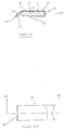
- FIGs. 1A-1B show a scraping apparatus or scraper 10 according to a first embodiment of the invention.
- a tubular housing 12 of scraper 10 has an opening 14 at one end which receives, for example, a hollow, threaded cap 16, and a tapered end 22 at the other end. Opening 14 allows a fluid 18 to be introduced into housing 12 and may be annular in shape. Tapered end 22 has two opposing faces 21 and 23.
- Cap 16 mates with opening 14 and can be removed to fill scraper 10 with fluid 18.
- cap 16 is a constrictive device such as a clamp or a pincher (not shown).
- opening 14 may be sealed by heat sealing, an adhesive, or the like.
- At least one hole or passage 20 allows, and preferably a plurality of holes or passages 20 allow, fluid 18 to flow from housing 12 and to be dispensed at the interface 26 between skin 24 of a patient and an adhesive device 28 (as shown in Fig. 1C).
- Fig. 1C shows an adhesive device 28 attached to skin 24.
- Adhesive device 28 may be, for example, a pressure sensitive, adhesive-backed electrocardiograph electrode attached to skin 24, an electrosurgical grounding pad (not shown), or a transdermal drug delivery patch (not shown).
- Adhesive device 28 includes adhesive 27 and foam backing 29.
- Fluid 18 is any gas or liquid capable of reducing or eliminating the adhesion of adhesive 27 on adhesive device 28.
- Fluid 18 may be a liquid or gas solvent or solvent-like material; a heated or cooled liquid or gas; or the like.
- a solvent or solvent-like material as used herein is any gas or liquid that will reduce or eliminate the adhesion of adhesive 27.
- the liquid solvent or solvent-like material is an alcohol such as propyl alcohol, isopropyl alcohol (rubbing alcohol), or the like.
- a gaseous solvent or solvent-like material may be used.
- the heated or cooled liquid or gas is, for example, an inert gas, an inert liquid, air or water.
- Fluid 18 may further include a small amount of an oil or detergent so that fluid 18 may be used on patients with particularly sensitive skin.
- a closure 25 prevents fluid 18 from escaping from scraper 10 and is held in a closed position by a spring force produced by faces 21 and 23 biased against one another at tapered end 22. Tapered end 22 and closure 25 are formed, for example, by thermoforming or compressing the material which forms housing 12.
- a wick (not shown in Figs. 1A-1B, but see Fig. 2B) formed of an absorbent material may be disposed in the tip of scraper 10.
- Housing 12 When used on hairy skin, the thin matted hair forms channels through which fluid 18 can flow by capillary action.
- Housing 12 is formed of a semi-rigid material such as polyvinyl chloride (PVC), polyethylene, polypropylene, metal such as aluminum foil, or the like that will retain its shape after compression.
- Housing 12 may be formed of two pieces of material which are connected together by heat sealing, gluing, or the like.
- housing 12 may be integrally formed by thermoforming, blow molding, extrusion, or injection molding and is similar to formed tubular containers used for toothpaste, gels and many other products in common usage.
- Figs. 2A and 2B show a second embodiment of the present invention.
- Scraper 30 has a width W which is somewhat larger than the width of the adhesive device 28 to be removed.
- scraper 30 is preferably about one-quarter to one-half inch wider than the width of the adhesive device 28 to be removed.
- Scraper 30 includes a rigid or semi-rigid housing 32 and a thin, flexible sheet or membrane 34.
- a cavity 36 formed in housing 32 is filled with fluid 18 through an aperture 38 which receives a plug 37 after filling.
- a sloping wall 40 of housing 32 provides scraper 30 with a wedge-like or blade-like surface which aids in removing adhesive device 28.
- Housing 32, flexible sheet or membrane 34, and sloping wall 40 are cemented together, for example, with an adhesive that cannot be dissolved by fluid 18.
- these components may be assembled using ultrasonic welding, heat sealing or other fastening means.
- These components also may be integrally formed.
- a dispenser 42 which may be a narrow slit (as shown in Figs. 2A, 2B, 4A, 4B, and 5) or a plurality of holes (as shown in Figs. 6A and 6B) is or are provided in housing 32.
- dispenser 42 is on the bottom of scraper 30.
- dispenser 42 may be formed at one location or more than one location at the end of scraper 30 as discussed below.
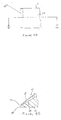
- Figs. 4A and 4B show a third embodiment of the present invention which is a variation of the embodiment shown in Figs. 2A and 2B.
- scraper 41 has sloping wall 40 which does not extend to meet the tip of housing 32, leaving a gap which forms dispenser 42 in sloping wall 40.
- dispenser 42 By disposing dispenser 42 above housing 32, fluid 18 is applied to adhesive 27 above skin 24 at the interface of adhesive 27 and foam backing 29.
- fluid 18 initially reduces or eliminates the adhesion of adhesive 27, for example by dissolving adhesive 27, in the direction from foam backing 29 to skin 24 to loosen the adhesion of adhesive device 28 on skin 24.
- a tip 43 of housing 32 lifts the front edge of adhesive device 28 to initiate removal of adhesive device 28 from skin 24 and allows fluid 18 to contact adhesive 27 at the intersection of adhesive 27 and skin 24.
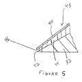
- Fig. 5 shows a fourth embodiment of the present invention which is another variation of the embodiment shown in Figs. 2A and 2B.
- scraper 45 has dispenser 42 disposed at an apex 46 formed by sloping wall 40 and housing 32.
- fluid 18 is dispensed from dispenser 42 and contacts adhesive 27 at the interface of adhesive 27 and skin 24 to reduce or eliminate the adhesion of adhesive 27, for example, by dissolving the layer of adhesive 27 in contact with skin 24. Then, the adhesion of adhesive 27 is progressively reduced or eliminated in the direction from the skin 24 to foam backing 29.
- the adhesion of adhesive 27 to skin 24 is reduced first at the interface of skin 24 and adhesive 27 allowing quick removal of adhesive device 28. Further, because dispenser 42 is not covered by a layer of adhesive 27 on adhesive device 28, as scraper 45 removes adhesive device 28, the chance of clogging dispenser 42 with adhesive 27 is reduced.
- Figs. 6A and 6B show a fifth embodiment of the present invention.
- scraper 47 has dispenser 42 which is at least one hole, and preferably a plurality of holes, disposed in the bottom of housing 32.
- the intersection 49 of housing 32 and sloping wall 40 first lifts the front edge of adhesive device 28 from skin 24 while fluid 18 is dispensed through the dispenser 42. Fluid 18 then flows along the surface of skin 24 to contact the interface 26 between skin 24 and adhesive 27 on adhesive device 28.
- dispenser 42 By disposing dispenser 42 on the bottom of housing 32, dispenser 42 will not become clogged with adhesive 27.
- dispenser 42 can be in both sloping wall 40 and housing 32 as discussed below with respect to Figs. 13-16. This configuration allows fluid 18 to be dispensed through sloping wall 40 and housing 32 at the same time.
- scraper 48 includes a reservoir 50 having tubular opening 52.
- Reservoir 50 is, for example, ball-shaped, cube-shaped, rectangular-shaped or regular- or irregular-shaped.
- Reservoir 50 is formed, for example, from a flexible material such as silicone rubber.
- Scraper 48 further includes a T-shaped distributor 54 having a sloping wall 56, a top wall 58, a bottom wall 60, and a dispenser 42. Sloping wall 56, top wall 58, and bottom wall 60 are assembled using an adhesive that cannot be dissolved by fluid 18.
- these components may be assembled using heat sealing or may be integrally formed.
- the T-shaped distributor 54 slideably fits into tubular opening 52 and dispenser 42 is in fluid communication via an annular opening 62 with reservoir 50.
- the T-shaped distributor 54 and reservoir 50 may have corresponding threads allowing the two components to be screwed together.
- Dispenser 42 may be a narrow slit or a plurality of holes.
- Fig. 8 shows a seventh embodiment of the present invention.
- scraper 64 includes reservoir 66 having an air passage 68 holding a check valve 69.
- reservoir 66 is ball-shaped, cube-shaped, rectangular-shaped, or regular- or irregular-shaped.
- Check valve 69 prevents the air contained within reservoir 66 from escaping through air passage 68 when reservoir 66 is compressed along lines "E.” Then, as reservoir 66 is allowed to expand, check valve 69 allows air to be sucked into reservoir 66 through air passage 68.
- Scraper 64 further includes a T-shaped distributor 70 having a sloping wall 71, a top wall 73, a bottom wall 75, and a dispenser 42.
- Dispenser 42 may be a narrow slit or a plurality of holes.
- the T-shaped distributor 70 has a fluid reservoir 72 holding fluid 18. Fluid reservoir 72 is in fluid communication with first annular opening 74 via second annular opening 76. First annular opening 74 has check valve 78 disposed therein between second annular opening 76 and reservoir 66. Check valve 78 allows one-way flow of air in the direction of sloping wall 71 when reservoir 66 is compressed along lines "E. Check valve 78 also prevents fluid 18 from entering reservoir 66 when the clinician stops compressing reservoir 66 along lines "E. Sloping wall 71, top wall 73, bottom wall 75, and fluid reservoir 72 are assembled using an adhesive that can not be dissolved by fluid 18. Optionally, those components may be assembled using heat sealing or may be integrally formed.
- Figs. 9A and 9B show an eighth embodiment of the present invention.
- Scraper 82 comprises flexible reservoir 84 which is formed, for example, of silicone rubber or thin aluminum.
- Flexible reservoir 84 is placed in V-shaped housing 86 which is formed, for example, of PVC, polyethylene, polypropylene, or the like.
- Flexible reservoir 84 and V-shaped housing 86 include dispenser 42 which may be a plurality of holes or a narrow slit.
- Wick 85 retains fluid 1 in scraper 82 until it is used.
- V-shaped housing 86 is compressed along lines "F" and "G" to force fluid 18 through dispenser 42.
- the tip of V-shaped housing 86 and fluid 18 contact interface 26 of adhesive device 28 and skin 24 to which adhesive device 28 is attached to remove adhesive device 28 as discussed with respect to the above-described embodiments.
- Fig. 10 shows a ninth embodiment of the present invention.
- Scraper 88 includes top plate 90, fluid container 92, and bottom plate 94.
- Top plate 90 is formed of a rigid or semi-rigid plastic and has beveled edge 96 which aids to remove adhesive device 28 from skin 24, and cut-out 98 in which fluid container 92 is disposed.
- the fluid container 92 is a flexible, thermoformed, squeezable container and has flat edge 100. Fluid container 92 is heat sealed or glued with adhesive along all four edges to top plate 90.
- the arrows marked “I” and “J” indicate the direction in which fluid container 92 is inserted into cut-out 98 of top plate 90.
- Top plate 90 and bottom plate 94 are assembled along the arrows marked "K” and are heat sealed or glued together with adhesive along three edges marked "a", "b", and “c” of bottom plate 94 leaving an opening at one end forming dispenser 42.
- Bottom plate 94 is formed of a rigid or semi-rigid plastic and, optionally, includes at least one formed groove or channel 102, and preferably a plurality of formed grooves or channels 102, extending from dispenser 42 to fluid container 92. Fluid container 92 is in fluid communication with dispenser 42 providing flow of fluid 18 along top plate 90 and bottom plate 94. Where groove or channel 102 is, or grooves or channels 102 are, present, bottom plate 96 may be glued or heat sealed along edge "d" thereof in the areas surrounding the groove(s) or channel(s). In this way, when bottom plate 94 is attached to top plate 90, the groove or channel 102 serves, or grooves or channels 102 serve, as flow paths for fluid 18 to reach dispenser 42.
- fluid pressure builds up in fluid container 92, forcing fluid 18 to flow between top and bottom plates 90 and 94 to dispenser 42. Fluid 18 then contacts interface 26 of adhesive device 28 and skin 24 to which adhesive device 28 is attached to reduce or eliminate the adhesion of adhesive 27 as discussed with respect to the above-described embodiments.
- scraper 88 is moved in a motion parallel, perpendicular or both with respect to interface 26 of adhesive device 28 and skin 24 to remove adhesive device 28 from skin 24.
- Figs. 11A and 11B show a tenth embodiment of the present invention which is a variation of the second embodiment shown in Figs. 2A and 2B.
- This embodiment further includes, however, an external source of a compressed gas such as inert gas or air, or any heated or cooled gas, or the like, which will not deteriorate the adhesion-reducing characteristics of fluid 18 and is suitable for medical use.
- scraper 124 includes a rigid housing 126 enclosing a cavity 128 which is filled with fluid 18.
- a sloping wall 40 of housing 126 provides scraper 124 with a wedge-like or blade-like surface which aids in removing adhesive device 28 attached to skin 24 of a patient.
- Housing 126 and sloping wall 40 are cemented together with an adhesive having adhesion strength which will not be reduced by fluid 18. Alternatively, these components can be heat sealed or may be integrally formed.
- a dispenser 42 which may be a narrow slit or a plurality of holes, is provided in an end of housing 126.
- Scraper 124 further includes a source of compressed gas 130 such as an inert gas or air.
- Compressed gas source 130 may be, for example, an air pump or a compressor which is attached via conduit 132 to aperture 38 in housing 126.
- Conduit 132 is of a length which allows the clinician to move about freely with scraper 124.
- the clinician engages compressed gas source 130 which supplies a compressed gas to cavity 128 and causes fluid pressure to build up in housing 126, forcing fluid 18 through dispenser 42. Fluid 18 contacts interface 26 of adhesive device 28 and skin 24 to which adhesive device 28 is attached to reduce the adhesion of adhesive 27 as discussed with respect to the above-described embodiments. Then, as compressed gas source 130 continues to supply compressed gas to cavity 128, scraper 124 is moved in a direction following line "P" as discussed with respect to Fig. 3 to remove adhesive device 28 from the patient. A wick 44 retains fluid 18 in scraper 124 until scraper 124 is in use. This embodiment allows the clinician to use scraper 124 without manually compressing the scraper.
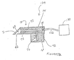
- Fig. 12 shows an eleventh embodiment of the present invention which is a variation of the seventh embodiment shown in Fig. 8.
- This embodiment further includes, however, an external source of a compressed gas such as an inert gas, air, or any heated or cooled gas, or the like, which will not deteriorate the adhesion characteristics of fluid 18 and is suitable for medical use.
- scraper 134 includes a T-shaped distributor 70 having a sloping wall 71, a top wall 73, a bottom wall 75, and a dispenser 42. Dispenser 42 may be a narrow slit or a plurality of holes.
- the T-shaped distributor 70 also has a fluid reservoir 72 in fluid communication with first annular opening 74 via second annular opening 76.
- First annular opening 74 has check valve 78 disposed therein. Sloping wall 71, top wall 73, bottom wall 75, and fluid reservoir 72 are assembled using an adhesive of which the adhesion will not be reduced by fluid 18. Optionally, those components may be heat sealed or may be integrally formed.
- Scraper 134 further includes a source of compressed gas 130 such as an inert gas or air.
- Compressed gas source 130 may be, for example, an air pump or an air compressor which is attached via conduit 132 to first annular opening 74.
- Check valve 78 allows one-way fluid flow in the direction of sloping wall 71 allowing gas to flow into annular first opening 74 when compressed gas source 130 is engaged. Check valve 78 also prevents fluid 18 from entering conduit 132 when compressed gas source 130 is disengaged.
- check valve 78 opens forcing the compressed gas at great speed therethrough and, by reducing the pressure (Bernoulii's equation) in first annular opening 74, the forced gas siphons and atomizes fluid 18 from fluid reservoir 72. Atomized fluid 18 exits T-shaped distributor 70 through dispenser 42 to contact interface 26 of adhesive device 28 and skin 24 to which adhesive 27 is attached as discussed with respect to the above-described embodiments.
- dispenser 42 may be disposed in one location or more than one location in the various scrapers.
- variations of the embodiments shown in Figs. 4B, 5, and 6A are shown in Figs. 13-16 with dispenser 42 in the top, bottom, and end of the scraper (as shown in Fig. 13); in the top and end of the scraper (as shown in Fig. 14); in the bottom and end of the scraper (as shown in Fig. 15); or in the top and bottom of the scraper (as shown in Fig. 16).
- the components of the above-described embodiments are formed from materials which will not be deteriorated or otherwise adversely affected by fluid 18.
- the components of the above-described scraper embodiments excluding wicks 44, 65, and 85; flexible sheets or membranes 34; and reservoirs 50 and 66 are formed from a thin plastic material such as polyvinyl chloride (PVC), polyethylene, polypropylene, or the like which will not be dissolved by fluid 18.
- these components are formed from a thin, metallic material such as aluminum.
- the adhesive used to bind the various components together is selected such that the adhesion thereof is not reduced by fluid 18.
- a hot melt adhesive is used that is not dissolved by fluid 18.
- Wicks 44, 65, and 85 typically are formed from an absorbent material such as a twisted, braided, or woven cotton or cotton blend, or the like.
- Flexible sheets or membranes 34 and reservoirs 50 and 66 are formed from, for example, a silicone rubber material, aluminum, or the like that will not be dissolved by fluid 18.
- Fluid 18 is any gas or liquid capable of reducing or eliminating the adhesion of adhesive 27 on adhesive device 28.
- Fluid 18 may be a liquid or gas solvent or solvent-like material; a heated or cooled liquid or gas; or the like.
- a solvent or solvent-like material as used herein is any gas or liquid that will reduce or eliminate the adhesion of adhesive 27.
- the liquid solvent or solvent-like material is an alcohol such as propyl alcohol, isopropyl alcohol (rubbing alcohol), or the like.
- a gaseous solvent or solvent-like material may be used.
- the heated or cooled liquid or gas is, for example, an inert gas, an inert liquid, air or water.
- Fluid 18 may further include a small amount of an oil or detergent so that fluid 18 may be used on patients with particularly sensitive skin.
- the width of the above described scrapers is somewhat larger than the adhesive device to be removed.
- the scraper is preferably approximately one-quarter to one-half inch wider than the width of the adhesive device to be removed.
Landscapes
- Health & Medical Sciences (AREA)
- Epidemiology (AREA)
- Engineering & Computer Science (AREA)
- Biomedical Technology (AREA)
- Heart & Thoracic Surgery (AREA)
- Vascular Medicine (AREA)
- Life Sciences & Earth Sciences (AREA)
- Animal Behavior & Ethology (AREA)
- General Health & Medical Sciences (AREA)
- Public Health (AREA)
- Veterinary Medicine (AREA)
- Surgical Instruments (AREA)
- Media Introduction/Drainage Providing Device (AREA)
Abstract
A scraping apparatus or scraper for contacting an adhesive device and skin to which the adhesive device is attached, at an interface between the adhesive device and the skin, to remove the adhesive device from the skin. In one configuration, the scraping apparatus includes a fluid for reducing the adhesion of the adhesive; an element for holding the fluid; and a scraping component. The scraping component is connected to and in fluid communication with the fluid holding element and has at least one first opening distal to the fluid holding element. The scraping apparatus also includes a structure for closing the first opening. In another configuration, the scraping apparatus further includes an element for propelling the fluid to the scraping component. The propelling element may be a compressed gas.
Description
- This invention relates generally to an apparatus for removing adhesive devices from skin and, more particularly, to an apparatus for removing adhesive medical devices.
- The removal of medical adhesive devices such as electrocardiograph electrodes, electrosurgical grounding pads, transdermal drug patches and medical tapes from the skin has long been a source of discomfort and pain for patients. Electrocardiograph electrodes, for example, are adhered to the patient's skin with strong, pressure sensitive adhesives that aid in providing stable electrical contact between the electrode and the skin. To achieve adequate contact between the adhesive device and the skin, the skin often must be shaved, further adding to the patient's discomfort. In the event the skin is not shaved the removal of the adhesive device usually tears the hair from the skin and causes the patient severe pain.
- The previous methods and devices used to remove adhesive medical devices from skin include contacting the adhesive device with a solvent, for example, on a gauze pad to dissolve the adhesive and then pulling the adhesive device from the skin. Alternatively, the adhesive device simply may be pulled from the skin without pretreating the adhesive device with a solvent. For permeable or semi-permeable adhesive devices, such as some medical tapes, contacting the adhesive device with a solvent sufficiently dissolves the adhesive and satisfactorily reduces the discomfort to the patient during removal. For impermeable adhesive devices, however, it is difficult or impossible to contact the adhesive sufficiently with solvent through the adhesive device. A new scraping apparatus is provided to overcome these shortcomings.
- It is an object of the present invention to provide an easy to use and inexpensive, disposable or reusable scraping apparatus to painlessly and quickly remove adhesive medical devices from the skin, to eliminate the need to shave the area on which the adhesive device is placed, to prevent hair from being torn out of the patient's skin, and to increase comfort for the patient during attachment (by omitting the necessity to shave the patient) and removal of the adhesive device.
- To achieve these and other objects, and in view of its purposes, the present invention provides a simple to use, inexpensive, disposable or reusable scraping apparatus (or scraper) which allows the painless and fast removal of medical adhesive devices from a patient's skin to which the adhesive device is attached. The apparatus contacts the interface between the adhesive device and the skin. The apparatus includes, in one configuration, a fluid for reducing or eliminating the adhesion of the adhesive on the adhesive device; an element for holding the fluid; and a scraping component connected to and in fluid communication with the fluid holding element. The scraping apparatus has at least one first opening distal to the fluid holding element and a closure for that first opening. Preferably, the scraping apparatus has more than one first opening at or around the scraping tip of the scraping component to allow the fluid to be dispensed therethrough.
- In another configuration, the fluid holding element is adjacent to the scraping component, and the scraping apparatus further includes an element for propelling the fluid to the scraping component. The propelling element is adjacent to and in fluid communication with the fluid holding element and the scraping component. The propelling element may be a compressed gas.
- It is to be understood that both the foregoing general description and the following detailed description are exemplary, but are not restrictive, of the invention.
- The invention is best understood from the following detailed description when read in connection with the accompanying drawings in which:
- Fig. 1A is a top view of one embodiment of the scraping apparatus according to the present invention;
- Fig. 1B is a sectional side view of the scraping apparatus shown in Fig. 1A taken along
line 1B-1B; - Fig. 1C is a sectional side view of an adhesive device attached to the skin of a patient;
- Fig. 2A is a sectional side view of a second embodiment of the scraping apparatus according to the invention taken along
line 2A-2A in Fig. 2B; - Fig. 2B is a bottom view of the scraping apparatus shown in Fig. 2A;
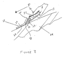
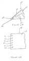
- Fig. 3 is a sectional side view of the scraping apparatus shown in Figs 2A and 2B being used to remove an adhesive device from the skin;
- Fig. 4A is a partial top view of a third embodiment of the scraping apparatus according to the present invention;
- Fig. 4B is a partial sectional side view of the scraping apparatus shown in Fig. 4A taken along
line 4B-4B; - Fig. 5 is a partial sectional side view of a fourth embodiment of the scraping apparatus according to the present invention;
- Fig. 6A is a partial sectional side view of a fifth embodiment of the scraping apparatus according to the present invention;
- Fig. 6B is a partial bottom view of the scraping apparatus shown in Fig. 6A;
- Fig. 7A is a top view of a sixth embodiment of the scraping apparatus according to the present invention;
- Fig. 7B is a side sectional view of the scraping apparatus shown in Fig. 7A taken along line 7B-7B;
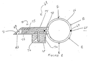
- Fig. 8 is a sectional side view of a seventh embodiment of the scraping apparatus according to the present invention;
- Fig. 9A is a sectional side view of an eighth embodiment of the scraping apparatus according to the present invention;
- Fig. 9B is a sectional top view of the scraping apparatus shown in Fig. 9A taken along
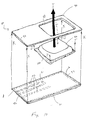
line 9B-9B; - Fig. 10 is an exploded perspective view of a ninth embodiment of the scraping apparatus according to the present invention;
- Fig. 11A is a sectional side view of a tenth embodiment of the scraping apparatus according to the invention taken along line 11A-11A in Fig. 11B;
- Fig. 11B is a bottom view of the scraping apparatus shown in Fig. 11A;
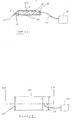
- Fig. 12 is a sectional side view of an eleventh embodiment of the scraping apparatus according to the present invention;
- Fig. 13 is a partial section side view of the embodiment shown in Fig. 5 with more than one dispenser location;
- Fig. 14 is a second partial sectional side view of the embodiment shown in Fig. 5 with more than one dispenser location;
- Fig. 15 is a partial sectional side view of the embodiment shown in Fig. 4B with more than one dispenser location; and
- Fig. 16 is a partial sectional side view of the embodiment shown in Fig. 6A with more than one dispenser location.
- Referring now to the drawing, wherein like reference numerals refer to like elements throughout, Figs. 1A-1B show a scraping apparatus or
scraper 10 according to a first embodiment of the invention. Atubular housing 12 ofscraper 10 has an opening 14 at one end which receives, for example, a hollow, threadedcap 16, and atapered end 22 at the other end. Opening 14 allows a fluid 18 to be introduced intohousing 12 and may be annular in shape.Tapered end 22 has two opposingfaces Cap 16 mates with opening 14 and can be removed to fillscraper 10 withfluid 18. Optionally,cap 16 is a constrictive device such as a clamp or a pincher (not shown). Also, opening 14 may be sealed by heat sealing, an adhesive, or the like. Intapered end 22, at least one hole orpassage 20 allows, and preferably a plurality of holes orpassages 20 allow, fluid 18 to flow fromhousing 12 and to be dispensed at theinterface 26 betweenskin 24 of a patient and an adhesive device 28 (as shown in Fig. 1C). - Fig. 1C shows an
adhesive device 28 attached toskin 24.Adhesive device 28 may be, for example, a pressure sensitive, adhesive-backed electrocardiograph electrode attached toskin 24, an electrosurgical grounding pad (not shown), or a transdermal drug delivery patch (not shown).Adhesive device 28 includes adhesive 27 andfoam backing 29.Fluid 18 is any gas or liquid capable of reducing or eliminating the adhesion of adhesive 27 onadhesive device 28.Fluid 18 may be a liquid or gas solvent or solvent-like material; a heated or cooled liquid or gas; or the like. A solvent or solvent-like material as used herein is any gas or liquid that will reduce or eliminate the adhesion ofadhesive 27. For example, the liquid solvent or solvent-like material is an alcohol such as propyl alcohol, isopropyl alcohol (rubbing alcohol), or the like. In addition, a gaseous solvent or solvent-like material may be used. The heated or cooled liquid or gas is, for example, an inert gas, an inert liquid, air or water.Fluid 18 may further include a small amount of an oil or detergent so that fluid 18 may be used on patients with particularly sensitive skin. Aclosure 25 prevents fluid 18 from escaping fromscraper 10 and is held in a closed position by a spring force produced byfaces tapered end 22.Tapered end 22 andclosure 25 are formed, for example, by thermoforming or compressing the material which formshousing 12. Optionally, other means may be used to prevent fluid 18 from escaping fromscraper 10. For example, a wick (not shown in Figs. 1A-1B, but see Fig. 2B) formed of an absorbent material may be disposed in the tip ofscraper 10. - In use, as a clinician compresses
tubular housing 12 in the direction of arrowsA and
and Bin Fig. 1B, fluid pressure builds up within
housing 12. Then, the compression forces acting on opposingfaces closure 25, and fluid pressure building withinhousing 12,cause closure 25 to open and release a volume offluid 18 throughpassage 20 sufficient to reduce or eliminate the adhesion ofadhesive 27. In this way fluid 18 contacts and reduces the adhesion of adhesive 27, for example by dissolvingadhesive 27 onadhesive device 28, and allowingadhesive device 28 to be painlessly removed fromskin 24. When the clinician stops compressingtubular housing 12 in the direction of arrowsAandB,opposing faces 21 and 23 are released and biased against one another to formclosure 25. When used on hairy skin, the thin matted hair forms channels through whichfluid 18 can flow by capillary action.Housing 12 is formed of a semi-rigid material such as polyvinyl chloride (PVC), polyethylene, polypropylene, metal such as aluminum foil, or the like that will retain its shape after compression.Housing 12 may be formed of two pieces of material which are connected together by heat sealing, gluing, or the like. Optionally,housing 12 may be integrally formed by thermoforming, blow molding, extrusion, or injection molding and is similar to formed tubular containers used for toothpaste, gels and many other products in common usage. - Figs. 2A and 2B show a second embodiment of the present invention.
Scraper 30 has a widthWwhich is somewhat larger than the width of theadhesive device 28 to be removed. For example,scraper 30 is preferably about one-quarter to one-half inch wider than the width of theadhesive device 28 to be removed.Scraper 30 includes a rigid orsemi-rigid housing 32 and a thin, flexible sheet ormembrane 34. Acavity 36 formed inhousing 32 is filled withfluid 18 through anaperture 38 which receives aplug 37 after filling. A slopingwall 40 ofhousing 32 providesscraper 30 with a wedge-like or blade-like surface which aids in removingadhesive device 28.Housing 32, flexible sheet ormembrane 34, and slopingwall 40 are cemented together, for example, with an adhesive that cannot be dissolved byfluid 18. Optionally, these components may be assembled using ultrasonic welding, heat sealing or other fastening means. These components also may be integrally formed. Adispenser 42 which may be a narrow slit (as shown in Figs. 2A, 2B, 4A, 4B, and 5) or a plurality of holes (as shown in Figs. 6A and 6B) is or are provided inhousing 32. - In use, when flexible sheet or
membrane 34 is pressed downward in the direction of arrowC,typically by handHof a clinician,fluid 18 is forced throughdispenser 42 as shown in Fig. 3. Then, forced by the downward pressure on flexible sheet ormembrane 34,fluid 18 is applied to interface 26 betweenskin 24 andadhesive device 28 to reduce or eliminate the adhesion ofadhesive 27. The user simultaneously pushesscraper 30 with a sweeping or scraping motion along skin 24 (in the direction of arrowP) to peeladhesive device 28 fromskin 24. In most cases the removal ofadhesive device 28 fromskin 24 can be accomplished with one hand. In special cases, however, as when removing adhesive devices from especially sensitive areas such as a woman's breast, it might be necessary to help removeadhesive device 28 by lifting the edge ofadhesive device 28 with one hand while operatingscraper 30 with the other. Awick 44 retainsfluid 18 inscraper 30 untilscraper 30 is used to removeadhesive device 28 fromskin 24. In the embodiments shown in Figs. 2A, 2B, 3, 6A, and 6B,dispenser 42 is on the bottom ofscraper 30. In the embodiments shown in Figs. 4A, 4B, and 5, however,dispenser 42 may be formed at one location or more than one location at the end ofscraper 30 as discussed below. - Figs. 4A and 4B show a third embodiment of the present invention which is a variation of the embodiment shown in Figs. 2A and 2B. In this embodiment,
scraper 41 has slopingwall 40 which does not extend to meet the tip ofhousing 32, leaving a gap which formsdispenser 42 in slopingwall 40. By disposingdispenser 42 abovehousing 32,fluid 18 is applied to adhesive 27 aboveskin 24 at the interface of adhesive 27 andfoam backing 29. In use, fluid 18 initially reduces or eliminates the adhesion of adhesive 27, for example by dissolvingadhesive 27, in the direction fromfoam backing 29 toskin 24 to loosen the adhesion ofadhesive device 28 onskin 24. Atip 43 ofhousing 32 lifts the front edge ofadhesive device 28 to initiate removal ofadhesive device 28 fromskin 24 and allows fluid 18 to contact adhesive 27 at the intersection of adhesive 27 andskin 24. - Fig. 5 shows a fourth embodiment of the present invention which is another variation of the embodiment shown in Figs. 2A and 2B. In this embodiment,
scraper 45 hasdispenser 42 disposed at an apex 46 formed by slopingwall 40 andhousing 32. In use,fluid 18 is dispensed fromdispenser 42 and contacts adhesive 27 at the interface of adhesive 27 andskin 24 to reduce or eliminate the adhesion of adhesive 27, for example, by dissolving the layer of adhesive 27 in contact withskin 24. Then, the adhesion ofadhesive 27 is progressively reduced or eliminated in the direction from theskin 24 tofoam backing 29. The adhesion of adhesive 27 toskin 24 is reduced first at the interface ofskin 24 and adhesive 27 allowing quick removal ofadhesive device 28. Further, becausedispenser 42 is not covered by a layer of adhesive 27 onadhesive device 28, asscraper 45 removesadhesive device 28, the chance of cloggingdispenser 42 with adhesive 27 is reduced. - Figs. 6A and 6B show a fifth embodiment of the present invention. In this embodiment,
scraper 47 hasdispenser 42 which is at least one hole, and preferably a plurality of holes, disposed in the bottom ofhousing 32. In use, theintersection 49 ofhousing 32 and slopingwall 40 first lifts the front edge ofadhesive device 28 fromskin 24 whilefluid 18 is dispensed through thedispenser 42.Fluid 18 then flows along the surface ofskin 24 to contact theinterface 26 betweenskin 24 and adhesive 27 onadhesive device 28. By disposingdispenser 42 on the bottom ofhousing 32,dispenser 42 will not become clogged withadhesive 27. Alternatively,dispenser 42 can be in both slopingwall 40 andhousing 32 as discussed below with respect to Figs. 13-16. This configuration allows fluid 18 to be dispensed through slopingwall 40 andhousing 32 at the same time. - Figs. 7A and 7B show a sixth embodiment of the present invention. In this embodiment,
scraper 48 includes a reservoir 50 having tubular opening 52. Reservoir 50 is, for example, ball-shaped, cube-shaped, rectangular-shaped or regular- or irregular-shaped. Reservoir 50 is formed, for example, from a flexible material such as silicone rubber.Scraper 48 further includes a T-shapeddistributor 54 having a slopingwall 56, atop wall 58, abottom wall 60, and adispenser 42. Slopingwall 56,top wall 58, andbottom wall 60 are assembled using an adhesive that cannot be dissolved byfluid 18. Optionally, these components may be assembled using heat sealing or may be integrally formed. The T-shapeddistributor 54 slideably fits into tubular opening 52 anddispenser 42 is in fluid communication via an annular opening 62 with reservoir 50. Optionally, the T-shapeddistributor 54 and reservoir 50 may have corresponding threads allowing the two components to be screwed together.Dispenser 42 may be a narrow slit or a plurality of holes. By squeezing reservoir 50 at its circumference along linesD,fluid 18 is forced throughdispenser 42 to contactinterface 26 ofadhesive device 28 andskin 24 to whichadhesive device 28 is attached as discussed with respect to the above-described embodiments.Wick 65 retainsfluid 18 inscraper 48 until reservoir 50 is squeezed. - Fig. 8 shows a seventh embodiment of the present invention. In this embodiment, scraper 64 includes
reservoir 66 having anair passage 68 holding acheck valve 69. For example,reservoir 66 is ball-shaped, cube-shaped, rectangular-shaped, or regular- or irregular-shaped. Checkvalve 69 prevents the air contained withinreservoir 66 from escaping throughair passage 68 whenreservoir 66 is compressed along lines "E." Then, asreservoir 66 is allowed to expand,check valve 69 allows air to be sucked intoreservoir 66 throughair passage 68. Scraper 64 further includes a T-shapeddistributor 70 having a slopingwall 71, atop wall 73, abottom wall 75, and adispenser 42.Dispenser 42 may be a narrow slit or a plurality of holes. The T-shapeddistributor 70 has afluid reservoir 72 holdingfluid 18.Fluid reservoir 72 is in fluid communication with firstannular opening 74 via secondannular opening 76. Firstannular opening 74 hascheck valve 78 disposed therein between secondannular opening 76 andreservoir 66. Checkvalve 78 allows one-way flow of air in the direction of slopingwall 71 whenreservoir 66 is compressed along lines "E. 78 also prevents fluid 18 from enteringCheck valvereservoir 66 when the clinician stops compressingreservoir 66 along lines "E. 71,Sloping walltop wall 73,bottom wall 75, andfluid reservoir 72 are assembled using an adhesive that can not be dissolved byfluid 18. Optionally, those components may be assembled using heat sealing or may be integrally formed. - In use, as
reservoir 66 is compressed at its circumference along linesE,check valve 69 closes andcheck valve 78 opens forcing air at great speed throughcheck valve 78 and, by reducing the pressure (Bernoulli's equation) in firstannular opening 74, the forced air siphons and atomizes fluid 18 fromfluid reservoir 72.Atomized fluid 18 exits T-shapeddistributor 70 throughdispenser 42 to contactinterface 26 ofadhesive device 28 andskin 24 to whichadhesive device 28 is attached as discussed with respect to the above-described embodiments. - Figs. 9A and 9B show an eighth embodiment of the present invention.
Scraper 82 comprisesflexible reservoir 84 which is formed, for example, of silicone rubber or thin aluminum.Flexible reservoir 84 is placed in V-shapedhousing 86 which is formed, for example, of PVC, polyethylene, polypropylene, or the like.Flexible reservoir 84 and V-shapedhousing 86 includedispenser 42 which may be a plurality of holes or a narrow slit.Wick 85 retains fluid 1 inscraper 82 until it is used. In use, V-shapedhousing 86 is compressed along lines "F" and "G" to forcefluid 18 throughdispenser 42. At the same time, the tip of V-shapedhousing 86 andfluid 18contact interface 26 ofadhesive device 28 andskin 24 to whichadhesive device 28 is attached to removeadhesive device 28 as discussed with respect to the above-described embodiments. - Fig. 10 shows a ninth embodiment of the present invention.
Scraper 88 includestop plate 90,fluid container 92, andbottom plate 94.Top plate 90 is formed of a rigid or semi-rigid plastic and has bevelededge 96 which aids to removeadhesive device 28 fromskin 24, and cut-out 98 in whichfluid container 92 is disposed. Thefluid container 92 is a flexible, thermoformed, squeezable container and hasflat edge 100.Fluid container 92 is heat sealed or glued with adhesive along all four edges totop plate 90. The arrows marked "I" and "J" indicate the direction in whichfluid container 92 is inserted into cut-out 98 oftop plate 90.Top plate 90 andbottom plate 94 are assembled along the arrows marked "K" and are heat sealed or glued together with adhesive along three edges marked "a", "b", and "c" ofbottom plate 94 leaving an opening at oneend forming dispenser 42. -
Bottom plate 94 is formed of a rigid or semi-rigid plastic and, optionally, includes at least one formed groove orchannel 102, and preferably a plurality of formed grooves orchannels 102, extending fromdispenser 42 tofluid container 92.Fluid container 92 is in fluid communication withdispenser 42 providing flow offluid 18 alongtop plate 90 andbottom plate 94. Where groove orchannel 102 is, or grooves orchannels 102 are, present,bottom plate 96 may be glued or heat sealed along edge "d" thereof in the areas surrounding the groove(s) or channel(s). In this way, whenbottom plate 94 is attached totop plate 90, the groove orchannel 102 serves, or grooves orchannels 102 serve, as flow paths forfluid 18 to reachdispenser 42. - In use, as
fluid container 92 is depressed in the direction of arrowL,fluid pressure builds up influid container 92, forcingfluid 18 to flow between top andbottom plates dispenser 42.Fluid 18 then contacts interface 26 ofadhesive device 28 andskin 24 to whichadhesive device 28 is attached to reduce or eliminate the adhesion of adhesive 27 as discussed with respect to the above-described embodiments. Then, asfluid container 92 is depressed,scraper 88 is moved in a motion parallel, perpendicular or both with respect to interface 26 ofadhesive device 28 andskin 24 to removeadhesive device 28 fromskin 24. - Figs. 11A and 11B show a tenth embodiment of the present invention which is a variation of the second embodiment shown in Figs. 2A and 2B. This embodiment further includes, however, an external source of a compressed gas such as inert gas or air, or any heated or cooled gas, or the like, which will not deteriorate the adhesion-reducing characteristics of
fluid 18 and is suitable for medical use. In this embodiment,scraper 124 includes arigid housing 126 enclosing acavity 128 which is filled withfluid 18. A slopingwall 40 ofhousing 126 providesscraper 124 with a wedge-like or blade-like surface which aids in removingadhesive device 28 attached toskin 24 of a patient.Housing 126 and slopingwall 40 are cemented together with an adhesive having adhesion strength which will not be reduced byfluid 18. Alternatively, these components can be heat sealed or may be integrally formed. Adispenser 42, which may be a narrow slit or a plurality of holes, is provided in an end ofhousing 126.Scraper 124 further includes a source ofcompressed gas 130 such as an inert gas or air.Compressed gas source 130 may be, for example, an air pump or a compressor which is attached viaconduit 132 toaperture 38 inhousing 126.Conduit 132 is of a length which allows the clinician to move about freely withscraper 124. - In use, the clinician engages compressed
gas source 130 which supplies a compressed gas tocavity 128 and causes fluid pressure to build up inhousing 126, forcingfluid 18 throughdispenser 42.Fluid 18 contacts interface 26 ofadhesive device 28 andskin 24 to whichadhesive device 28 is attached to reduce the adhesion of adhesive 27 as discussed with respect to the above-described embodiments. Then, as compressedgas source 130 continues to supply compressed gas tocavity 128,scraper 124 is moved in a direction following line "P" as discussed with respect to Fig. 3 to removeadhesive device 28 from the patient. Awick 44 retainsfluid 18 inscraper 124 untilscraper 124 is in use. This embodiment allows the clinician to usescraper 124 without manually compressing the scraper. - Fig. 12 shows an eleventh embodiment of the present invention which is a variation of the seventh embodiment shown in Fig. 8. This embodiment further includes, however, an external source of a compressed gas such as an inert gas, air, or any heated or cooled gas, or the like, which will not deteriorate the adhesion characteristics of
fluid 18 and is suitable for medical use. In this embodiment,scraper 134 includes a T-shapeddistributor 70 having a slopingwall 71, atop wall 73, abottom wall 75, and adispenser 42.Dispenser 42 may be a narrow slit or a plurality of holes. The T-shapeddistributor 70 also has afluid reservoir 72 in fluid communication with firstannular opening 74 via secondannular opening 76. Firstannular opening 74 hascheck valve 78 disposed therein. Slopingwall 71,top wall 73,bottom wall 75, andfluid reservoir 72 are assembled using an adhesive of which the adhesion will not be reduced byfluid 18. Optionally, those components may be heat sealed or may be integrally formed.Scraper 134 further includes a source ofcompressed gas 130 such as an inert gas or air.Compressed gas source 130 may be, for example, an air pump or an air compressor which is attached viaconduit 132 to firstannular opening 74. Checkvalve 78 allows one-way fluid flow in the direction of slopingwall 71 allowing gas to flow into annularfirst opening 74 when compressedgas source 130 is engaged. Checkvalve 78 also prevents fluid 18 from enteringconduit 132 when compressedgas source 130 is disengaged. - In use, as compressed gas is supplied from compressed
gas source 130,check valve 78 opens forcing the compressed gas at great speed therethrough and, by reducing the pressure (Bernoulii's equation) in firstannular opening 74, the forced gas siphons and atomizes fluid 18 fromfluid reservoir 72.Atomized fluid 18 exits T-shapeddistributor 70 throughdispenser 42 to contactinterface 26 ofadhesive device 28 andskin 24 to which adhesive 27 is attached as discussed with respect to the above-described embodiments. - In each of the above-described embodiments,
dispenser 42 may be disposed in one location or more than one location in the various scrapers. For example, variations of the embodiments shown in Figs. 4B, 5, and 6A are shown in Figs. 13-16 withdispenser 42 in the top, bottom, and end of the scraper (as shown in Fig. 13); in the top and end of the scraper (as shown in Fig. 14); in the bottom and end of the scraper (as shown in Fig. 15); or in the top and bottom of the scraper (as shown in Fig. 16). In the configurations with more than one dispenser to dispensefluid 18, if one opening becomes blocked with adhesive or other contaminant or debris, the other opening(s) allowfluid 18 to be dispensed therethrough. In this way, an ample supply offluid 18 is continuously dispensed at or around the portion of the scraper used for scraping the adhesive device from the skin. - The components of the above-described embodiments are formed from materials which will not be deteriorated or otherwise adversely affected by
fluid 18. For example, the components of the above-described scraper embodiments, excludingwicks membranes 34; andreservoirs 50 and 66 are formed from a thin plastic material such as polyvinyl chloride (PVC), polyethylene, polypropylene, or the like which will not be dissolved byfluid 18. Optionally, these components are formed from a thin, metallic material such as aluminum. The adhesive used to bind the various components together is selected such that the adhesion thereof is not reduced byfluid 18. For example, a hot melt adhesive is used that is not dissolved byfluid 18.Wicks membranes 34 andreservoirs 50 and 66 are formed from, for example, a silicone rubber material, aluminum, or the like that will not be dissolved byfluid 18.Fluid 18 is any gas or liquid capable of reducing or eliminating the adhesion of adhesive 27 onadhesive device 28. -
Fluid 18 may be a liquid or gas solvent or solvent-like material; a heated or cooled liquid or gas; or the like. A solvent or solvent-like material as used herein is any gas or liquid that will reduce or eliminate the adhesion ofadhesive 27. For example, the liquid solvent or solvent-like material is an alcohol such as propyl alcohol, isopropyl alcohol (rubbing alcohol), or the like. In addition, a gaseous solvent or solvent-like material may be used. The heated or cooled liquid or gas is, for example, an inert gas, an inert liquid, air or water.Fluid 18 may further include a small amount of an oil or detergent so that fluid 18 may be used on patients with particularly sensitive skin. - The width of the above described scrapers is somewhat larger than the adhesive device to be removed. For example, the scraper is preferably approximately one-quarter to one-half inch wider than the width of the adhesive device to be removed.
- Although illustrated and described herein with reference to certain specific embodiments, the present invention is nevertheless not intended to be limited to the details shown. Rather, various modifications may be made in the details within the scope and range of equivalents of the claims and without departing from the spirit of the invention.
Claims (44)
- A scraping apparatus for contacting an adhesive device and skin to which the adhesive device is attached, at an interface between the adhesive device and the skin, to remove the adhesive device from the skin, said apparatus comprising:fluid;means for holding said fluid;means for scraping the adhesive device from the skin, said scraping means having a top, a bottom and an end, and connected to and in fluid communication with said fluid holding means and having at least one first opening distal to said fluid holding means; and means for closing said first opening.
- The scraping apparatus according to claim 1, wherein said fluid is selected from the group consisting of a solvent and a solvent-like material.
- The scraping apparatus according to claim 1 wherein said fluid is selected from the group consisting of a heated liquid, heated gas, cooled liquid, and cooled gas.
- The scraping apparatus according to claim 3, wherein said fluid is selected from the group consisting of heated and cooled inert gas, inert liquid, air and water.
- The scraping apparatus according to claim 2, wherein said solvent and solvent-like material is alcohol.
- The scraping apparatus according to claim 5, wherein said alcohol is selected from the group consisting of propyl alcohol and isopropyl alcohol.
- The scraping apparatus according to claim 2, wherein said solvent and solvent-like material are heated.
- The scraping apparatus according to claim 2, wherein said solvent and solvent-like material are cooled.
- The scraping apparatus according to claim 1, wherein said fluid holding means has means for introducing said fluid into said holding means and said apparatus further comprises means for sealing said introducing means proximate said introducing means.
- The scraping apparatus according to claim 9, wherein said introducing means is an annular hole and said sealing means is selected from the group consisting of a cylindrical plug, a cap, a clamp, a pincher, an adhesive, and heat sealing.
- The scraping apparatus according to claim 1, wherein said fluid holding means is a semi-rigid housing surrounding a cavity.
- The scraping apparatus according to claim 11, wherein said fluid holding means has an open top and a flexible sheet covering said open top.
- The scraping apparatus according to claim 1, wherein said fluid holding means is a rigid housing surrounding a cavity.
- The scraping apparatus according to claim 13, wherein said fluid holding means has an open top and a flexible sheeting covering said open top.
- The scraping apparatus according to claim 1, wherein said fluid holding means is a semi-rigid reservoir surrounding a cavity.
- The scraping apparatus according to claim 1, wherein said fluid holding means is a semi-rigid housing surrounding a cavity disposed between a first member, having a cut out into which said housing is inserted and a beveled edge, and a second member.
- The scraping apparatus according to claim 16, wherein said scraping means is said beveled edge of said first member.
- The scraping apparatus according to claim 1, wherein said holding means is a V-shaped rigid housing having a tip and surrounding a flexible membrane.
- The scraping apparatus according to claim 18, wherein said scraping means is said tip of said V-shaped housing.
- The scraping apparatus according to claim 1, wherein said scraping means is a tapered end of said fluid holding means having two opposing faces.
- The scraping apparatus according to claim 20, wherein said first opening closing means is said opposing faces biased against one another.
- The scraping apparatus according to claim 1, wherein said scraping means is a wedge-shaped member.
- The scraping apparatus according to claim 1, wherein said scraping means is a T-shaped member having a wedge-shaped end.
- The scraping apparatus according to claim 1, wherein said fluid holding means has an edge and said scraping means is said edge of said fluid holding means.
- The scraping apparatus according to claim 1, wherein said first opening closing means is disposed inside said scraping means.
- The scraping apparatus according to claim 1, whereinsaid first opening is selected from the group consisting of a slit, a groove, a slot, a hole, and a plurality of slits, grooves, slots, and holes; andsaid first opening closing means is a wick.
- The scraping apparatus according to claim 1, wherein said first opening is in said top of said scraping means.
- The scraping apparatus according to claim 1, wherein said first opening is in said bottom of said scraping means.
- The scraping apparatus according to claim 1, wherein said first opening is in said end of said scraping means.
- The scraping apparatus according to claim 1, wherein said scraping means has two said first openings and one said first opening is in said top and another said first opening is in said bottom.
- The scraping apparatus according to claim 1, wherein said scraping means has two said first openings and one said first opening is in said top and another said first opening is in said end.
- The scraping apparatus according to claim 1, wherein said scraping means has two said first openings and one said first opening is in said bottom and another said first opening is in said end.
- The scraping apparatus according to claim 1, wherein said scraping means has three said first openings, and one said first opening is in said top, another said first opening is in said bottom, and another said first opening is in said end of said scraping means.
- The scraping apparatus according to claim 1, further comprising a means for propelling said fluid to said first opening.
- The scraping apparatus according to claim 34, wherein said propelling means is a compressed gas.
- The scraping apparatus according to claim 34, wherein said compressed gas is selected from the group consisting of inert gas, air, heated inert gas, cooled inert gas, heated air and cooled air.
- The scraping apparatus according to claim 34, wherein said propelling means is gravity.
- The scraping apparatus according to claim 35, wherein said fluid holding means is adjacent said scraping means;said compressed gas atomizes said fluid, and said compressed gas is adjacent to and in fluid communication with said fluid holding means and said scraping means; andsaid scraping apparatus further comprises means for preventing said fluid from entering said propelling means, and said preventing means is connected to and in fluid communication with said propelling means.
- The scraping apparatus according to claim 38, wherein said preventing means is a first check valve.
- The scraping apparatus according to claim 38, wherein said compressed gas is supplied from an apparatus selected from the group consisting of a flexible reservoir having a third opening in fluid communication with ambient air and a check valve disposed in said third opening; an air pump; and an air compressor.
- The scraping apparatus according to claim 38, wherein said fluid holding means is a housing surrounding a cavity; said scraping means is a wedge-shaped member; and said first opening closing means is disposed inside said scraping means.
- The scraping apparatus according to claim 41, wherein said first opening is at least one slit and said first opening closing means is a wick.
- A scraping apparatus for contacting an adhesive device and skin to which the adhesive device is attached, at an interface between the adhesive device and the skin, said apparatus comprising:solvent;means for holding said solvent;means for scraping the adhesive device from the skin, said scraping means connected to and in fluid communication with said solvent holding means and having at least one first opening distal to said solvent holding means;means for propelling said solvent, said propelling means adjacent to and in fluid communication with said solvent holding means and said scraping means; andmeans for preventing said solvent from entering said propelling means, said preventing means connected to and in fluid communication with said propelling means.
- The scraping apparatus according to claim 43, whereinsaid means for holding said solvent is a housing surrounding a cavity;said scraping means is a wedge-shaped member;said first opening is a slit;said first opening closing means is disposed inside said scraping means and is a wick;said propelling means is selected from the group consisting of a flexible, ball-shaped reservoir having a third opening in fluid communication with the ambient air and a first check valve disposed in said third opening; an air pump; and an air compressor; andsaid preventing means is a second check valve.
Applications Claiming Priority (2)
| Application Number | Priority Date | Filing Date | Title |
|---|---|---|---|
| US626056 | 1996-04-01 | ||
| US08/626,056 US5803639A (en) | 1996-04-01 | 1996-04-01 | Apparatus for removing medical adhesive devices from skin |
Publications (2)
| Publication Number | Publication Date |
|---|---|
| EP0804918A2 true EP0804918A2 (en) | 1997-11-05 |
| EP0804918A3 EP0804918A3 (en) | 1997-12-03 |
Family
ID=24508771
Family Applications (1)
| Application Number | Title | Priority Date | Filing Date |
|---|---|---|---|
| EP97105242A Withdrawn EP0804918A3 (en) | 1996-04-01 | 1997-03-27 | Apparatus for removing medical adhesive devices from skin |
Country Status (3)
| Country | Link |
|---|---|
| US (1) | US5803639A (en) |
| EP (1) | EP0804918A3 (en) |
| CA (1) | CA2201065A1 (en) |
Families Citing this family (21)
| Publication number | Priority date | Publication date | Assignee | Title |
|---|---|---|---|---|
| DE19710543A1 (en) * | 1997-03-14 | 1998-09-17 | Beiersdorf Ag | Presentation to reduce the adhesive strength of adhesive tapes |
| US6579271B1 (en) * | 2000-02-11 | 2003-06-17 | Careguide Systems, Inc. | Patient discharge system and method for self-care of a post-surgery drain |
| US7017577B2 (en) | 2002-01-18 | 2006-03-28 | Matich Ronald D | Face mask with seal and neutralizer |
| US20070050883A1 (en) * | 2002-01-18 | 2007-03-08 | Matich Ronald D | Face mask with seal and neutralizer |
| US6767151B1 (en) * | 2003-04-22 | 2004-07-27 | Richard L. Owens | Dispenser/spreader article for spackling and paste |
| US20090089087A1 (en) * | 2005-11-21 | 2009-04-02 | Kevin Todd Kotecki | Method for Developing and Marketing a Post Operative Home Recovery Kit for Use by a Patient After Discharge From a Hospital and for Recuperation At Home |
| US7396976B2 (en) * | 2006-04-21 | 2008-07-08 | I Did It, Inc. | Easy-to-peel securely attaching bandage |
| US20070245567A1 (en) * | 2006-04-21 | 2007-10-25 | Laufer Jeremy S | Spatula with steam scraping mechanism |
| US20080064016A1 (en) * | 2006-06-29 | 2008-03-13 | Careguide Systems, Inc. | Integrated blood sugar control, blood pressure control and coronary artery self-care system and method |
| US20080038704A1 (en) * | 2006-06-29 | 2008-02-14 | Careguide Systems, Inc. | Integrated blood pressure control and coronary artery self-care system and method |
| US20080050709A1 (en) * | 2006-06-29 | 2008-02-28 | Careguide Systems, Inc. | Integrated blood sugar control, blood pressure control and heart failure self-care system and method |
| US7578071B2 (en) * | 2006-10-27 | 2009-08-25 | Group One Ltd. | Fluid reservoir wiper assembly |
| US8272140B2 (en) | 2006-10-27 | 2012-09-25 | Group One Limited | Fluid reservoir assembly |
| US8957277B2 (en) | 2009-04-27 | 2015-02-17 | Avery Dennison Corporation | Disruptable adhesive layer for fluid activated debonding |
| CA2760294C (en) | 2009-04-27 | 2017-05-16 | Avery Dennison Corporation | Systems, methods and materials for delivery and debonding on demand |
| DK2773304T3 (en) | 2011-10-31 | 2016-05-02 | Avery Dennison Corp | Adhesive layers, which can be torn apart, to the fluid-activated solution. |
| CN104870567B (en) | 2012-10-22 | 2018-09-07 | 艾利丹尼森公司 | It is dispersed in the hybrid material of the crosslinked micro-gel particles in adhesive |
| US20160122088A1 (en) * | 2013-06-06 | 2016-05-05 | Michael Jamison | An Applicator |
| WO2015119853A1 (en) | 2014-02-10 | 2015-08-13 | 3M Innovative Properties Company | Multipurpose dispenser for spreadable wall repair compound |
| CN112155679B (en) * | 2020-10-28 | 2021-10-12 | 王冬冬 | Gynaecology's chamber mirror minimal access surgery scalpel |
| WO2022201036A1 (en) * | 2021-03-23 | 2022-09-29 | Newpace Ltd. | Medical patch removal |
Family Cites Families (35)
| Publication number | Priority date | Publication date | Assignee | Title |
|---|---|---|---|---|
| US1268271A (en) * | 1917-01-25 | 1918-06-04 | August Nelson | Mop. |
| US1598811A (en) * | 1925-10-17 | 1926-09-07 | Joseph L Ferrin | Cleaning tool |
| US1738471A (en) * | 1927-05-11 | 1929-12-03 | Amore Michael J D | Liquid-applying implement |
| US1861790A (en) * | 1927-12-19 | 1932-06-07 | Henry A Dreffein | Apparatus for heating billets or the like |
| US1789959A (en) * | 1928-08-29 | 1931-01-27 | John H Fedeler | Stopper |
| US1982833A (en) * | 1933-09-14 | 1934-12-04 | Joseph J Schmerler | Spreader for paste tubes |
| US2104161A (en) * | 1934-12-18 | 1938-01-04 | Koukal Louis | Window glass cleaning implement |
| US2014149A (en) * | 1935-05-31 | 1935-09-10 | S S Stafford Inc | Spreading nozzle for adhesive containers |
| US2321333A (en) * | 1941-01-27 | 1943-06-08 | Harriet E Cole | Closure device |
| US2584735A (en) * | 1949-11-19 | 1952-02-05 | William G Pancoast | Dispensing applicator and massaging device |
| US2804767A (en) * | 1955-06-21 | 1957-09-03 | Harvey P Schoen | Gun type trowel |
| US2832980A (en) * | 1956-10-05 | 1958-05-06 | Frank D O'neill | Cleaning device |
| US2943338A (en) * | 1957-12-05 | 1960-07-05 | Lowen Stanley | Container closure and applicator |
| USRE25556E (en) * | 1958-06-25 | 1964-04-21 | Figure | |
| US3041655A (en) * | 1960-07-26 | 1962-07-03 | William H Entler | Eaves gutter cleaning device |
| US3108313A (en) * | 1961-11-30 | 1963-10-29 | John E Summers | Brick mason mortar applicator |
| US3351969A (en) * | 1965-05-19 | 1967-11-14 | Vincent C Cline | Flexible scraper |
| NL6901549A (en) * | 1968-10-21 | 1970-04-23 | ||
| US3534428A (en) * | 1968-12-04 | 1970-10-20 | Molson Ind Ltd Les Ind Molson | De-labelling apparatus |
| US3782600A (en) * | 1972-06-13 | 1974-01-01 | Borden Inc | Co-dispenser applicator and spatula cap |
| US3998654A (en) * | 1974-01-28 | 1976-12-21 | Minnesota Mining And Manufacturing Company | Method of removing adhesive |
| DE3306946A1 (en) * | 1983-02-28 | 1984-08-30 | Friedrich Grohe Armaturenfabrik Gmbh & Co, 5870 Hemer | CLEANING AND DISHWASHER |
| DE8506654U1 (en) * | 1985-03-07 | 1985-05-15 | Töpfer GmbH Kulmbach, 8650 Kulmbach | Device for peeling off a label |
| US4750883A (en) * | 1987-02-09 | 1988-06-14 | Drake Harry N | Device for cleaning rain gutters |
| US4812070A (en) * | 1987-05-21 | 1989-03-14 | Masco Corporation Of Indiana | Brush and scraper attachment for faucet spray handle |
| US4867981A (en) * | 1987-11-19 | 1989-09-19 | Henry Greenwald | Tape releasing composition and method of using same |
| US5007753A (en) * | 1988-12-30 | 1991-04-16 | England Jr Raymond B | Window cleaning apparatus with rotatable head |
| FR2662145B1 (en) * | 1990-05-18 | 1992-08-14 | Hilbert Raymond | TANK OF LIQUID, VISCOUS OR PASTY PRODUCT, PROVIDED WITH AN APPLICATOR. |
| FR2663611B1 (en) * | 1990-06-26 | 1992-10-09 | Rg Plastiques | DEVICE FOR PACKAGING AND APPLYING A PRODUCT CONTAINED IN A FLEXIBLE AND SEALED TUBE. |
| US5189756A (en) * | 1990-12-17 | 1993-03-02 | Tamae Sprunger | Snow and ice remover |
| USD338298S (en) | 1991-02-25 | 1993-08-10 | Grim Sr Robert D | Combined ice scraper and liquid dispenser |
| US5316403A (en) * | 1992-12-15 | 1994-05-31 | Mansour Amin F | Apparatus for applying a film of liquid |
| US5433782A (en) * | 1993-05-14 | 1995-07-18 | Filbert; John A. | Envelope and stamp moisturizer |
| US5312197A (en) * | 1993-05-24 | 1994-05-17 | Abramson Daniel J | Inter-digital surgical scrub brush for reducing skin trauma |
| US5415488A (en) * | 1994-04-18 | 1995-05-16 | Macgibbon; David A. | Shaving cream dispenser |
-
1996
- 1996-04-01 US US08/626,056 patent/US5803639A/en not_active Expired - Fee Related
-
1997
- 1997-03-26 CA CA002201065A patent/CA2201065A1/en not_active Abandoned
- 1997-03-27 EP EP97105242A patent/EP0804918A3/en not_active Withdrawn
Also Published As
| Publication number | Publication date |
|---|---|
| US5803639A (en) | 1998-09-08 |
| CA2201065A1 (en) | 1997-10-01 |
| EP0804918A3 (en) | 1997-12-03 |
Similar Documents
| Publication | Publication Date | Title |
|---|---|---|
| US5803639A (en) | Apparatus for removing medical adhesive devices from skin | |
| US11647984B2 (en) | Gel application system | |
| US9889283B2 (en) | Dispensing applicator for fluids | |
| US8511923B2 (en) | Dispensing applicator for fluids | |
| US6254580B1 (en) | Suction blister sampling | |
| EP2142067B1 (en) | Liquid applicator with an angled elongated head | |
| EP3046616B1 (en) | Liquid applicator | |
| EP1010400A2 (en) | Dental capsule for containing and dispensing low viscosity dental material | |
| US3981304A (en) | Dispensing and applicating device and production of same | |
| EP2841144B1 (en) | Liquid applicator | |
| JP2004532698A (en) | Equipment for operation of needle or abrader arrays | |
| CN102712407A (en) | Dispensing device incorporating frangible section, along with dispensing method | |
| CA1048444A (en) | Dispensing and applicating device and production of same | |
| JP2003175077A (en) | Single dose patient dispensing drug dispenser with applicator | |
| GB2185880A (en) | Liquid dispenser having an absorbent applicator tip | |
| US20150209228A1 (en) | Squeezable Ampule with Breakable Seal in Nose Bleed Kit | |
| US10478602B2 (en) | Antiseptic swab with activation button | |
| US10828477B2 (en) | Dispensing applicator for fluids | |
| CN114727859A (en) | Oral treatment device | |
| CN219210476U (en) | Oil wiper for oiling surface of medical endoscope insertion tube | |
| JP2006096397A (en) | Package with applicator | |
| ITMO20130097A1 (en) | AN APPLICATOR OF FLUID SUBSTANCES |
Legal Events
| Date | Code | Title | Description |
|---|---|---|---|
| PUAI | Public reference made under article 153(3) epc to a published international application that has entered the european phase |
Free format text: ORIGINAL CODE: 0009012 |
|
| PUAL | Search report despatched |
Free format text: ORIGINAL CODE: 0009013 |
|
| AK | Designated contracting states |
Kind code of ref document: A2 Designated state(s): CH DE DK ES FR GB IT LI SE |
|
| AK | Designated contracting states |
Kind code of ref document: A3 Designated state(s): CH DE DK ES FR GB IT LI SE |
|
| 17P | Request for examination filed |
Effective date: 19980602 |
|
| STAA | Information on the status of an ep patent application or granted ep patent |
Free format text: STATUS: THE APPLICATION HAS BEEN WITHDRAWN |
|
| 18W | Application withdrawn |
Withdrawal date: 19990325 |