EP0804328B1 - Process and device for preparing foam using carbon dioxide dissolved under pressure - Google Patents
Process and device for preparing foam using carbon dioxide dissolved under pressure Download PDFInfo
- Publication number
- EP0804328B1 EP0804328B1 EP95924975A EP95924975A EP0804328B1 EP 0804328 B1 EP0804328 B1 EP 0804328B1 EP 95924975 A EP95924975 A EP 95924975A EP 95924975 A EP95924975 A EP 95924975A EP 0804328 B1 EP0804328 B1 EP 0804328B1
- Authority
- EP
- European Patent Office
- Prior art keywords
- carbon dioxide
- reactive
- foam
- grating
- mixing
- Prior art date
- Legal status (The legal status is an assumption and is not a legal conclusion. Google has not performed a legal analysis and makes no representation as to the accuracy of the status listed.)
- Expired - Lifetime
Links
- CURLTUGMZLYLDI-UHFFFAOYSA-N Carbon dioxide Chemical compound O=C=O CURLTUGMZLYLDI-UHFFFAOYSA-N 0.000 title abstract description 66
- 229910002092 carbon dioxide Inorganic materials 0.000 title abstract description 33
- 239000001569 carbon dioxide Substances 0.000 title abstract description 33
- 238000000034 method Methods 0.000 title abstract description 7
- 239000006260 foam Substances 0.000 title description 26
- 239000000203 mixture Substances 0.000 abstract description 33
- 239000007788 liquid Substances 0.000 abstract description 20
- 239000000463 material Substances 0.000 abstract description 6
- 229920003023 plastic Polymers 0.000 abstract description 4
- 239000004033 plastic Substances 0.000 abstract description 4
- 239000003795 chemical substances by application Substances 0.000 abstract 1
- 238000004519 manufacturing process Methods 0.000 description 6
- 229920005862 polyol Polymers 0.000 description 6
- 150000003077 polyols Chemical class 0.000 description 6
- 229920005830 Polyurethane Foam Polymers 0.000 description 5
- 239000011496 polyurethane foam Substances 0.000 description 5
- IJGRMHOSHXDMSA-UHFFFAOYSA-N Atomic nitrogen Chemical compound N#N IJGRMHOSHXDMSA-UHFFFAOYSA-N 0.000 description 4
- 239000004604 Blowing Agent Substances 0.000 description 4
- 230000015572 biosynthetic process Effects 0.000 description 4
- 238000005187 foaming Methods 0.000 description 4
- 239000007789 gas Substances 0.000 description 4
- 239000012948 isocyanate Substances 0.000 description 4
- 150000002513 isocyanates Chemical class 0.000 description 4
- 239000008258 liquid foam Substances 0.000 description 4
- 230000003068 static effect Effects 0.000 description 4
- YMWUJEATGCHHMB-UHFFFAOYSA-N Dichloromethane Chemical compound ClCCl YMWUJEATGCHHMB-UHFFFAOYSA-N 0.000 description 3
- 238000006243 chemical reaction Methods 0.000 description 3
- 238000010030 laminating Methods 0.000 description 3
- 238000003475 lamination Methods 0.000 description 3
- OFBQJSOFQDEBGM-UHFFFAOYSA-N Pentane Chemical compound CCCCC OFBQJSOFQDEBGM-UHFFFAOYSA-N 0.000 description 2
- 238000009826 distribution Methods 0.000 description 2
- 238000005516 engineering process Methods 0.000 description 2
- 239000002360 explosive Substances 0.000 description 2
- 239000011888 foil Substances 0.000 description 2
- 229910052757 nitrogen Inorganic materials 0.000 description 2
- XLYOFNOQVPJJNP-UHFFFAOYSA-N water Substances O XLYOFNOQVPJJNP-UHFFFAOYSA-N 0.000 description 2
- 0 CC(CC(CC1)*=*2CC1(C)C(C)C2)*1C*(C)CCC1 Chemical compound CC(CC(CC1)*=*2CC1(C)C(C)C2)*1C*(C)CCC1 0.000 description 1
- 238000010521 absorption reaction Methods 0.000 description 1
- 239000000654 additive Substances 0.000 description 1
- 230000004888 barrier function Effects 0.000 description 1
- 238000007664 blowing Methods 0.000 description 1
- 150000001875 compounds Chemical class 0.000 description 1
- 230000001934 delay Effects 0.000 description 1
- 230000001419 dependent effect Effects 0.000 description 1
- 230000000694 effects Effects 0.000 description 1
- 230000007613 environmental effect Effects 0.000 description 1
- 238000001704 evaporation Methods 0.000 description 1
- 239000004872 foam stabilizing agent Substances 0.000 description 1
- 125000004435 hydrogen atom Chemical group [H]* 0.000 description 1
- 239000002667 nucleating agent Substances 0.000 description 1
- 238000006068 polycondensation reaction Methods 0.000 description 1
- 229920001228 polyisocyanate Polymers 0.000 description 1
- 239000005056 polyisocyanate Substances 0.000 description 1
- 230000002265 prevention Effects 0.000 description 1
- 239000003380 propellant Substances 0.000 description 1
- 239000011541 reaction mixture Substances 0.000 description 1
- 230000002040 relaxant effect Effects 0.000 description 1
- 239000007787 solid Substances 0.000 description 1
- 238000003860 storage Methods 0.000 description 1
- 239000000126 substance Substances 0.000 description 1
Images


Classifications
-
- C—CHEMISTRY; METALLURGY
- C08—ORGANIC MACROMOLECULAR COMPOUNDS; THEIR PREPARATION OR CHEMICAL WORKING-UP; COMPOSITIONS BASED THEREON
- C08J—WORKING-UP; GENERAL PROCESSES OF COMPOUNDING; AFTER-TREATMENT NOT COVERED BY SUBCLASSES C08B, C08C, C08F, C08G or C08H
- C08J9/00—Working-up of macromolecular substances to porous or cellular articles or materials; After-treatment thereof
- C08J9/04—Working-up of macromolecular substances to porous or cellular articles or materials; After-treatment thereof using blowing gases generated by a previously added blowing agent
- C08J9/12—Working-up of macromolecular substances to porous or cellular articles or materials; After-treatment thereof using blowing gases generated by a previously added blowing agent by a physical blowing agent
- C08J9/122—Hydrogen, oxygen, CO2, nitrogen or noble gases
-
- B—PERFORMING OPERATIONS; TRANSPORTING
- B29—WORKING OF PLASTICS; WORKING OF SUBSTANCES IN A PLASTIC STATE IN GENERAL
- B29C—SHAPING OR JOINING OF PLASTICS; SHAPING OF MATERIAL IN A PLASTIC STATE, NOT OTHERWISE PROVIDED FOR; AFTER-TREATMENT OF THE SHAPED PRODUCTS, e.g. REPAIRING
- B29C44/00—Shaping by internal pressure generated in the material, e.g. swelling or foaming ; Producing porous or cellular expanded plastics articles
- B29C44/34—Auxiliary operations
- B29C44/3469—Cell or pore nucleation
- B29C44/3473—Cell or pore nucleation by shearing forces
-
- B—PERFORMING OPERATIONS; TRANSPORTING
- B29—WORKING OF PLASTICS; WORKING OF SUBSTANCES IN A PLASTIC STATE IN GENERAL
- B29C—SHAPING OR JOINING OF PLASTICS; SHAPING OF MATERIAL IN A PLASTIC STATE, NOT OTHERWISE PROVIDED FOR; AFTER-TREATMENT OF THE SHAPED PRODUCTS, e.g. REPAIRING
- B29C44/00—Shaping by internal pressure generated in the material, e.g. swelling or foaming ; Producing porous or cellular expanded plastics articles
- B29C44/34—Auxiliary operations
- B29C44/3469—Cell or pore nucleation
- B29C44/348—Cell or pore nucleation by regulating the temperature and/or the pressure, e.g. suppression of foaming until the pressure is rapidly decreased
-
- B—PERFORMING OPERATIONS; TRANSPORTING
- B29—WORKING OF PLASTICS; WORKING OF SUBSTANCES IN A PLASTIC STATE IN GENERAL
- B29C—SHAPING OR JOINING OF PLASTICS; SHAPING OF MATERIAL IN A PLASTIC STATE, NOT OTHERWISE PROVIDED FOR; AFTER-TREATMENT OF THE SHAPED PRODUCTS, e.g. REPAIRING
- B29C44/00—Shaping by internal pressure generated in the material, e.g. swelling or foaming ; Producing porous or cellular expanded plastics articles
- B29C44/34—Auxiliary operations
- B29C44/36—Feeding the material to be shaped
- B29C44/46—Feeding the material to be shaped into an open space or onto moving surfaces, i.e. to make articles of indefinite length
- B29C44/461—Feeding the material to be shaped into an open space or onto moving surfaces, i.e. to make articles of indefinite length dispensing apparatus, e.g. dispensing foaming resin over the whole width of the moving surface
-
- C—CHEMISTRY; METALLURGY
- C08—ORGANIC MACROMOLECULAR COMPOUNDS; THEIR PREPARATION OR CHEMICAL WORKING-UP; COMPOSITIONS BASED THEREON
- C08J—WORKING-UP; GENERAL PROCESSES OF COMPOUNDING; AFTER-TREATMENT NOT COVERED BY SUBCLASSES C08B, C08C, C08F, C08G or C08H
- C08J2375/00—Characterised by the use of polyureas or polyurethanes; Derivatives of such polymers
- C08J2375/04—Polyurethanes
Definitions
- the present invention relates to a method and an apparatus for Production of foams using carbon dioxide dissolved under pressure Blowing agent, the mass to be foamed preferably under pressure liquid carbon dioxide mixed and then expanded to form foam becomes.
- Liquid foam products in particular become foamable materials used for plastics that due to foaming starting polyaddition or polycondensation reaction to the foam plastic Harden.
- the invention relates to polyurethane foams.
- At least one of the Reactive components (polyisocyanate and isocyanate-reactive hydrogen atoms containing compounds, especially polyols) with a liquid or gaseous Propellant added, then mixed with the other component and the mixture obtained either discontinuously in a form or continuously conveyed to a conveyor belt where the mixture foams and hardens.
- liquid carbon dioxide has already been proposed many times as a blowing agent (see, for example, US Pat. No. 4,337,318).
- carbon dioxide has so far not found its way into the technology, apparently due to the difficulties in producing uniform foams when the reactive mixture has to be relaxed from pressures between 10 and 20 bar.
- the problem of foaming is said to be by means of liquid carbon dioxide in that the reactive mixture additionally Nitrogen is added as a bubble nucleating agent, the relaxation gradually is carried out and also created a special storage device for the foam becomes. No details of the process have been disclosed to date.
- the shear rate should preferably be between 10 5 and 10 8 / sec.
- the present invention relates to a method for producing Foams according to claim 1, and a device according to Claim 2.
- liquid carbon dioxide-containing mixture under “liquid carbon dioxide-containing mixture” is a Understand elevated pressure homogeneous liquid from which to relax below the equilibrium pressure dependent on the carbon dioxide content above Ambient pressure carbon dioxide is released.
- the liquid containing carbon dioxide Mixing can be done by dissolving gaseous or solid carbon dioxide in the at least one reactive component or by mixing with liquid carbon dioxide.
- those with extended gaps in the flow direction are one Gap width from 0.05 to 1.5 mm, preferably 0.1 to 1 mm, particularly preferably 0.1 to 0.3 mm, suitable.
- the expansion of the column in the direction of flow is preferably at least 50 to 30 times, particularly preferably that 80 to 200 times the gap width.
- the slit grid is 70 to 95% of the grid cross-sectional plane covers, i.e. the inside width of the lattice is only 5 to 30%, preferably Is 7 to 15%, so that after passing through the grid a sufficient there is more space between the individual material flows, that also an explosive sudden lateral expansion of the material flow due to the formation of gas bubbles with no significant sudden increase in Forward speed can take place.
- the viscosity of the reactive mixture containing liquid carbon dioxide can be 50 to 2,000 mPas, preferably 70 to 800 mPas, particularly preferably 70 to 120 mPas. Taking into account the viscosity, the shear stress of the mixture when passing through the sieve is at least 1,000 Pa. Shear stresses between 10 7 and 10 10 Pa are particularly preferred.
- the required pressure of the reactive mixture before it passes through the grid depends on the amount of liquid carbon dioxide dissolved. That's the way it is Equilibrium pressure with a content of 2 wt .-% carbon dioxide in the Reactive mixture at 7 bar, with a content of 4 wt .-% carbon dioxide in the Reactive mixture at 11 bar (temperature of the reactive mixture is the same Ambient temperature).
- the pressure of the reactive mixture is preferred before passing through the grille 1.1 times to 1.8 times, particularly preferably 1.3 times to 1.6 times the equilibrium pressure be.
- Equilibrium pressure denotes the pressure at which one carbon dioxide atmosphere prevailing over the reactive mixture in the Equilibrium with the dissolved carbon dioxide.
- a pressure above the equilibrium pressure before the passage through the grid is required so that the mixture is still entering the grid is homogeneous, i.e. that no formation of Gas bubbles occur.
- the pressure is reduced from above Equilibrium pressure to a pressure below the equilibrium pressure.
- the throttling can be done by a perforated or slotted plate, which in the Distance of 0.5 to 3 mm is arranged in front of the grille, the width of the Passage openings 3 to 15 mm and the free passage area 1 to 10% of the Area of the perforated plate can be.
- the pressure is preferably Mix before entering the grid 0.7 to 1.0 of the equilibrium pressure.
- a liquid polyurethane foam (Froth) with a density of 50 to 80 kg / m 3 immediately after the reactive mixture has passed through the sieve using 2 to 3% by weight of CO 2, based on the reactive mixture .
- water is preferably additionally used as blowing agent, which also produces carbon dioxide as the blowing gas in reaction with the isocyanate. In this way it is possible to produce soft foams with a bulk density of less than 15 kg / m 3 .
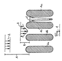
- Fig. 1 explains the principle of generating high shear according to the invention Passage through the grid.
- the enlarged cross section is shown through Ridges of the grids la to ld running perpendicular to the plane of the drawing. Further are the speed profiles 2, 3 and 4 of the reactive mixture at distance A, B and C shown from the grid entry plane.
- Fig. 2 shows schematically in general form the process for the production of Polyurethane foam. It turns from a reservoir 1 through the metering pump 2 Polyol pumped into the static mixer 3.
- the container 4 becomes liquid carbon dioxide via the heat exchanger 5 also the static mixer fed and mixed here with the polyol. Mixing is preferably carried out in the static mixer 3 with a measured at the output of the static mixer Pressure P from 60 to 150 bar.
- a heat exchanger 5 ensures that that the reactive mixture even after heat absorption from pumps and Mixing units etc. remains below the critical temperature of 31 ° C.
- the Mixture of polyol and liquid carbon dioxide is the mixing head 6th fed where mixing with the isocyanate (arrow 7) and others Additives such as foam stabilizers, etc. (arrow 8).
- Additives such as foam stabilizers, etc.
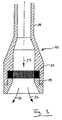
- the relaxation device consists of a tube 18, which may be a Can have extension and in the output side, the grid 21 on the Screw 19 can be fixed.
- the liquid containing carbon dioxide Reactive mixture hits the grid in the direction of arrow 23 and emerges as a liquid Foam out along arrows 24.
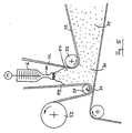
- FIG. 4 shows a plant according to the invention for producing block foam using the foam-forming device according to the invention.
- the reactive mixture passes through the foam-forming device containing the grid 10 as a liquid foam 30 and is on the lower liner 31 that on a conveyor belt, not shown runs, filed.
- the top liner 32 is guided over a roller 33, which in the on the lower laminating film 31st deposited and thus conveyed foam so that a barrier 34th forms the distribution of the foam across the width and the prevention of Air entry into the space between the lamination films 31 and 32 is used.
- the foam begins due to the now starting chemical reaction to expand (35).
- FIG. 5 shows a plant for the production of block foam according to FIG. 4, wherein however, an auxiliary liner 50 from above towards the lower one Laminating film 31 is supplied.
- the auxiliary liner 50 is by means of a roll 51 guided against the lower lamination film 31 and deflected and again wound 52.
- the liquid foam 30 is in the substantially vertical extending upper liner 32 and auxiliary liner 50 formed trough 54 promoted.
- the relaxation device formed in the form of an elongated tube 26, which Grid 21 worked out transversely to a circumferential sector parallel to the axis Grid slot is formed.
- the reactive mixture containing liquid carbon dioxide is fed along arrow 23.
- the foam occurs all over Width of the tube 26 substantially radially. Your length of the tube 26 can be adapted to the width of the block foam to be produced, so that the Distribution of the foam over the width of the conveyor belt (Fig. 4) immediately given is.
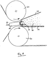
- FIG. 7 shows the device according to FIG. 5 in cross section AA.
- the foaming device 10 is between the deflection rollers 40 and 41, by means of which the laminating foils 31 and 32 are arranged.
- the lamination films 31 are preferably and 32 guided so that they slide on the foam discharge device 10th are passed so that air can enter between the foils 31 and 32 safely is avoided.
- slides 31 and 32 shown at a distance from the foam discharge device.
Landscapes
- Chemical & Material Sciences (AREA)
- Engineering & Computer Science (AREA)
- Materials Engineering (AREA)
- Health & Medical Sciences (AREA)
- Chemical Kinetics & Catalysis (AREA)
- Medicinal Chemistry (AREA)
- Polymers & Plastics (AREA)
- Organic Chemistry (AREA)
- Manufacture Of Porous Articles, And Recovery And Treatment Of Waste Products (AREA)
- Polyurethanes Or Polyureas (AREA)
Abstract
Description
Die vorliegende Erfindung betrifft ein Verfahren und eine Vorrichtung zur Herstellung von Schäumen mittels unter Druck gelöstem Kohlendioxid als Treibmittel, wobei die zu verschäumende Masse unter Druck mit vorzugsweise flüssigem Kohlendioxid vermischt und anschließend unter Schaumbildung entspannt wird. Als verschäumbare Massen werden insbesondere flüssige Ausgangsprodukte für Kunststoffe eingesetzt, die aufgrund einer nach dem Verschäumen einsetzenden Polyadditions- oder Polykondensationsreaktion zum Schaum-Kunststoff aushärten. Speziell bezieht sich die Erfindung auf Polyurethan-Schaumstoffe.The present invention relates to a method and an apparatus for Production of foams using carbon dioxide dissolved under pressure Blowing agent, the mass to be foamed preferably under pressure liquid carbon dioxide mixed and then expanded to form foam becomes. Liquid foam products in particular become foamable materials used for plastics that due to foaming starting polyaddition or polycondensation reaction to the foam plastic Harden. In particular, the invention relates to polyurethane foams.
Bei der Herstellung von Polyurethan-Schaumstoffen wird mindestens eine der Reaktivkomponenten (Polyisocyanat und Isocyanat-reaktive Wasserstoffatome aufweisende Verbindungen, insbesondere Polyole) mit einem flüssigen oder gasförmigen Treibmittel versetzt, danach mit der anderen Komponente vermischt und die erhaltene Mischung entweder diskontinuierlich in eine Form oder kontinuierlich auf ein Transportband gefördert, wo die Mischung aufschäumt und aushärtet.In the production of polyurethane foams, at least one of the Reactive components (polyisocyanate and isocyanate-reactive hydrogen atoms containing compounds, especially polyols) with a liquid or gaseous Propellant added, then mixed with the other component and the mixture obtained either discontinuously in a form or continuously conveyed to a conveyor belt where the mixture foams and hardens.
Zur Erzeugung des Schaums haben eine Reihe von Verfahren breite Anwendung in der Technik gefunden. Einerseits werden bei niedriger Temperatur verdampfende Flüssigkeiten, wie niedermolekulare Chlorfluorkohlenwasserstoffe, Methylenchlorid, Pentan usw. eingesetzt, die aus der noch flüssigen Reaktivmischung verdampfen und Bläschen bilden. Ferner kann in die Reaktivmischung bzw. in eine der Komponenten Luft eingeschlagen werden (mechanische Schaumerzeugung) und schließlich wird bei Polyurethanschäumen Wasser als Treibmittel der Polyolkomponente zugesetzt, das nach Vermischung der Isocyanatkomponente durch Reaktion mit dem Isocyanat Kohlendioxid als Schäumgas freisetzt (chemische Schaumerzeugung). A number of methods have been widely used to produce the foam found in technology. On the one hand, evaporating at low temperature Liquids such as low molecular weight chlorofluorocarbons, methylene chloride, Pentane, etc., used from the still liquid reactive mixture evaporate and form bubbles. Furthermore, in the reactive mixture or in one of the air components is hammered in (mechanical foam generation) and finally water is used as a blowing agent in polyurethane foams Polyol component added after mixing the isocyanate component releases carbon dioxide as a foaming gas by reaction with the isocyanate (chemical Foam generation).
Aus Gründen der Umweltvertrãglichkeit, der Arbeitshygiene und aufgrund der vergleichsweise hohen Löslichkeit von flüssigem Kohlendioxid in der Polyolkomponente wurde flüssiges Kohlendioxid bereits vielfach als Treibmittel vorgeschlagen (s. z. B. US-A-4 337 318). Jedoch hat Kohlendioxid bisher keinen Eingang in die Technik gefunden, offenbar aufgrund der Schwierigkeiten, bei der erforderlichen Entspannung der Reaktivmischung von Drücken zwischen 10 und 20 bar gleichmäßige Schäume zu erzeugen. Dabei besteht das Problem einerseits darin, dass unmittelbar nach der Entspannung das Kohlendioxid relativ plötzlich verdampft, so dass eine sehr starke Volumenvergrößerung der Reaktionsmischung um einen Faktor von beispielsweise ca. 10 erfolgt, die schwer zu beherrschen ist, und andererseits die Reaktivmischung zu Freisetzungsverzügen des Kohlendioxids neigt, die 3 bis 6 bar unterhalb des Gleichgewichtsdampfdrucks von CO2 bei der jeweiligen Temperatur liegen könen, so dass es zu plötzlichen explosionsartigen Kohlendioxidfreisetzungen kommt mit der Folge, dass große Blasen oder Lunker in den Schaumstoff eingeschlossen sind.For reasons of environmental compatibility, occupational hygiene and the comparatively high solubility of liquid carbon dioxide in the polyol component, liquid carbon dioxide has already been proposed many times as a blowing agent (see, for example, US Pat. No. 4,337,318). However, carbon dioxide has so far not found its way into the technology, apparently due to the difficulties in producing uniform foams when the reactive mixture has to be relaxed from pressures between 10 and 20 bar. The problem on the one hand is that immediately after the expansion, the carbon dioxide evaporates relatively suddenly, so that there is a very large increase in volume of the reaction mixture by a factor of about 10, for example, which is difficult to control, and on the other hand the reactive mixture leads to delays in the release of the carbon dioxide tends to be 3 to 6 bar below the equilibrium vapor pressure of CO 2 at the respective temperature, so that sudden explosive releases of carbon dioxide occur, with the result that large bubbles or cavities are enclosed in the foam.
Gemäß einer Firmenschrift der Cannon-Group soll das Problem der Verschäumung mittels flüssigem Kohlendioxid dadurch gelingen, dass der Reaktivmischung zusätzlich Stickstoff als Blasenkeimbildner zugesetzt wird, die Entspannung stufenweise durchgeführt wird und ferner eine besondere Ablagevorrichtung für den Schaum geschaffen wird. Einzelheiten des Verfahrens wurden bisher nicht bekannt.According to a Cannon Group company letter, the problem of foaming is said to be by means of liquid carbon dioxide in that the reactive mixture additionally Nitrogen is added as a bubble nucleating agent, the relaxation gradually is carried out and also created a special storage device for the foam becomes. No details of the process have been disclosed to date.
Nach einem nicht vorveröffentlichten Vorschlag der Anmelder (EP-A-0 767 728) gelingt es, eine Vielzahl von mikroskopischen Blasenkeimen zu erzeugen, wenn die Reaktivmischung während der Entspannung durch ein feinmaschiges Sieb hohen Schergeschwindigkeiten in der Größenordnung von oberhalb 500/sec, vorzugsweise oberhalb 5.000/sec, insbesondere bevorzugt oberhalb 105/sec ausgesetzt wird. Erfindungsgemäß wird nun vorgeschlagen, die flüssiges Kohlendioxid enthaltende Reaktivmischung durch ein Spaltgitter enger Spaltweite zu drücken und dabei zu entspannen.According to a not previously published proposal by the applicants (EP-A-0 767 728) it is possible to generate a large number of microscopic bubble nuclei if the reactive mixture during the expansion through a fine-meshed sieve has high shear rates in the order of magnitude of above 500 / sec, preferably above 5,000 / sec, particularly preferably above 10 5 / sec. According to the invention, it is now proposed to press the liquid carbon dioxide-containing reactive mixture through a slit grid with a narrow gap width and to relax in the process.
Vorzugsweise soll die Schergeschwindigkeit zwischen 105 und 108/sec betragen. The shear rate should preferably be between 10 5 and 10 8 / sec.
Gegenstand der vorliegenden Erfindung ist ein Verfahren zur Herstellung von
Schaumstoffen
gemäß Anspruch 1, sowie eine Vorrichtung gemäß
Anspruch 2.The present invention relates to a method for producing
Foams
according to claim 1, and a device according to
Im Folgenden wird unter "flüssiges Kohlendioxid enthaltende Mischung" eine unter erhöhtem Druck stehende homogene Flüssigkeit verstanden, aus der nach Entspannen unter den vom Kohlendioxidgehalt abhängigen Gleichgewichtsdruck oberhalb Umgebungsdruck Kohlendioxid freigesetzt wird. Die flüssiges Kohlendioxid enthaltende Mischung kann durch Auflösen von gasförmigem oder festem Kohlendioxid in der mindestens einen Reaktivkomponente oder durch Vermischen mit flüssigem Kohlendioxid hergestellt worden sein.In the following, under "liquid carbon dioxide-containing mixture" is a Understand elevated pressure homogeneous liquid from which to relax below the equilibrium pressure dependent on the carbon dioxide content above Ambient pressure carbon dioxide is released. The liquid containing carbon dioxide Mixing can be done by dissolving gaseous or solid carbon dioxide in the at least one reactive component or by mixing with liquid carbon dioxide.
Als Spaltgitter sind solche mit in Strömungsrichtung ausgedehnten Spalten einer Spaltweite von 0,05 bis 1,5 mm, vorzugsweise 0,1 bis 1 mm, insbesondere bevorzugt 0,1 bis 0,3 mm, geeignet. Die Ausdehnung der Spalte in Strömungsrichtung beträgt vorzugsweise mindestens das 50- bis 30-fache, besonders bevorzugt das 80- bis 200-fache, der Spaltweite.As slit grids, those with extended gaps in the flow direction are one Gap width from 0.05 to 1.5 mm, preferably 0.1 to 1 mm, particularly preferably 0.1 to 0.3 mm, suitable. The expansion of the column in the direction of flow is preferably at least 50 to 30 times, particularly preferably that 80 to 200 times the gap width.
Beim Durchgang durch die Reaktivmischung wird dieser ein Geschwindigkeitsprofil aufgeprägt, das die geforderte hohe Scherung zur Blasenkeimerzeugung bewirkt.As it passes through the reactive mixture, it becomes a speed profile imprinted, which causes the required high shear to produce bladder nuclei.
Femer hat sich für die erfindungsgemäß vorteilhafte Blasenkeim- und Schaumbildung als vorteilhaft erwiesen, wenn das Spaltgitter 70 bis 95 % der Gitter-Querschnittsebene abdeckt, d.h. die lichte Weite des Gitters lediglich 5 bis 30 %, vorzugsweise 7 bis 15 %, beträgt, so dass nach Durchtritt durch das Gitter ein hinreichend größer Zwischenraum zwischen den einzelnen Materialströmen besteht, dass eine auch explosionsartige plötzliche seitliche Ausdehnung des Materialstroms aufgrund der Ausbildung von Gasblasen ohne wesentliche plötzliche Erhöhung der Vorwärtsgeschwindigkeit erfolgen kann.It has also been found to be advantageous for the formation of bladder germ and foam according to the invention proven to be advantageous when the slit grid is 70 to 95% of the grid cross-sectional plane covers, i.e. the inside width of the lattice is only 5 to 30%, preferably Is 7 to 15%, so that after passing through the grid a sufficient there is more space between the individual material flows, that also an explosive sudden lateral expansion of the material flow due to the formation of gas bubbles with no significant sudden increase in Forward speed can take place.
Die Viskosität der flüssiges Kohlendioxid enthaltenden Reaktivmischung kann 50 bis 2.000 mPas, vorzugsweise 70 bis 800 mPas, insbesondere bevorzugt 70 bis 120 mPas, betragen. Unter Berücksichtigung der Viskosität beträgt die Scherspannung der Mischung beim Durchgang durch das Sieb mindestens 1.000 Pa. Insbesondere bevorzugt sind Scherspannungen zwischen 107 und 1010 Pa.The viscosity of the reactive mixture containing liquid carbon dioxide can be 50 to 2,000 mPas, preferably 70 to 800 mPas, particularly preferably 70 to 120 mPas. Taking into account the viscosity, the shear stress of the mixture when passing through the sieve is at least 1,000 Pa. Shear stresses between 10 7 and 10 10 Pa are particularly preferred.
Der erforderliche Druck der Reaktivmischung vor dem Durchtritt durch das Gitter ist abhängig von der gelösten Menge an flüssigem Kohlendioxid. So liegt der Gleichgewichtsdruck bei einem Gehalt von 2 Gew.-% Kohlendioxid in der Reaktivmischung bei 7 bar, bei einem Gehalt von 4 Gew.-% Kohlendioxid in der Reaktivmischung bei 11 bar (Temperatur des Reaktivgemisches ist gleich Umgebungstemperatur). Erfindungsgemäß bevorzugt soll der Druck der Reaktivmischung vor dem Durchtritt durch das Gitter das 1,1-fache bis 1,8-fache, besonders bevorzugt das 1,3-fache bis 1,6-fache, des Gleichgewichtsdrucks betragen. Gleichgewichtsdruck bezeichnet dabei denjenigen Druck, bei dem eine über der Reaktivmischung herrschende Kohlendioxid-Atmosphäre im Gleichgewicht mit dem gelösten Kohlendioxid steht.The required pressure of the reactive mixture before it passes through the grid depends on the amount of liquid carbon dioxide dissolved. That's the way it is Equilibrium pressure with a content of 2 wt .-% carbon dioxide in the Reactive mixture at 7 bar, with a content of 4 wt .-% carbon dioxide in the Reactive mixture at 11 bar (temperature of the reactive mixture is the same Ambient temperature). According to the invention, the pressure of the reactive mixture is preferred before passing through the grille 1.1 times to 1.8 times, particularly preferably 1.3 times to 1.6 times the equilibrium pressure be. Equilibrium pressure denotes the pressure at which one carbon dioxide atmosphere prevailing over the reactive mixture in the Equilibrium with the dissolved carbon dioxide.
Ein oberhalb des Gleichgewichtsdrucks liegender Druck vor dem Durchgang durch
das Gitter ist erforderlich, damit die Mischung beim Eintritt in das Gitter noch
homogen ist, d.h., daß vor dem Durchtritt durch das Gitter noch keine Bildung von
Gasblasen erfolgt. Jedoch kann erfindungsgemäß bevorzugt unmittelbar vor dem
Eintritt der Mischung in das Gitter eine Drosselung des Druckes von oberhalb
Gleichgewichtsdruck auf einen Druck unterhalb des Gleichgewichtsdruckes erfolgen.
Die Drosselung kann durch eine Loch- oder Schlitzplatte erfolgen, die im
Abstand von 0,5 bis 3 mm vor dem Gitter angeordnet ist, wobei die Weite der
Durchtrittsöffnungen 3 bis 15 mm und die freie Durchtrittsfläche 1 bis 10 % der
Fläche der Lochplatte betragen kann. Vorzugsweise beträgt der Druck der
Mischung vor dem Eintritt in das Gitter 0,7 bis 1,0 des Gleichgewichtsdrucks.A pressure above the equilibrium pressure before the passage through
the grid is required so that the mixture is still entering the grid
is homogeneous, i.e. that no formation of
Gas bubbles occur. However, according to the invention, preferably immediately before
When the mixture enters the grid, the pressure is reduced from above
Equilibrium pressure to a pressure below the equilibrium pressure.
The throttling can be done by a perforated or slotted plate, which in the
Distance of 0.5 to 3 mm is arranged in front of the grille, the width of the
Aufgrund der hervorragenden Wirkung der Entspannung der Reaktivmischung durch das Gitter im Hinblick auf die Blasenkeimbildung ist die Mitverwendung von Luft oder Stickstoff erfindungsgemäß nicht erforderlich.Because of the excellent effect of relaxing the reactive mixture through the grid with regard to the formation of bubble nuclei is the joint use of air or nitrogen not required according to the invention.
Erfindungsgemäß gelingt es, unmittelbar nach Durchtritt der Reaktivmischung durch das Sieb einen Flüssig-Polyurethan-Schaum (Froth) mit einer Dichte von 50 bis 80 kg/m3 bei Einsatz von 2 bis 3 Gew.-% CO2 bezogen auf die Reaktivmischung zu erzeugen. Zur Erzeugung von Schäumen mit noch geringerer Dichte wird vorzugsweise zusätzlich Wasser als Treibmittel eingesetzt, das in Reaktion mit dem Isocyanat ebenfalls Kohlendioxid als Treibgas erzeugt. Auf diese Weise gelingt es, Weichschäume mit einer Rohdichte von unter 15 kg/m3 zu erzeugen.According to the invention, it is possible to produce a liquid polyurethane foam (Froth) with a density of 50 to 80 kg / m 3 immediately after the reactive mixture has passed through the sieve using 2 to 3% by weight of CO 2, based on the reactive mixture . To produce foams with an even lower density, water is preferably additionally used as blowing agent, which also produces carbon dioxide as the blowing gas in reaction with the isocyanate. In this way it is possible to produce soft foams with a bulk density of less than 15 kg / m 3 .
Die Erfindung wird nachfolgend anhand der beigefügten Figuren näher erläutert:The invention is explained in more detail below with reference to the attached figures:
Fig. 1 erläutert das erfindungsgemäße Prinzip der Erzeugung hoher Scherung beim
Durchgang durch das Gitter. Dargestellt ist der vergrößerte Querschnitt durch
senkrecht zur Zeichnungsebene verlaufende Stege des Gitters la bis ld. Ferner
sind die Geschwindigkeitsprofile 2, 3 und 4 der Reaktivmischung im Abstand A,
B und C von der Gittereintrittsebene dargestellt.Fig. 1 explains the principle of generating high shear according to the invention
Passage through the grid. The enlarged cross section is shown through
Ridges of the grids la to ld running perpendicular to the plane of the drawing. Further
are the
Fig. 2 zeigt schematisch in allgemeiner Form das Verfahren zur Herstellung von
Polyurethanschaum. Dabei wird aus einem Vorratsbehälter 1 über die Dosierpumpe
2 Polyol in den Statikmischer 3 gepumpt. Aus dem Behälter 4 wird
flüssiges Kohlendioxid über den Wärmeaustauscher 5 ebenfalls dem Statikmischer
zugeführt und hier mit dem Polyol vermischt. Vorzugsweise erfolgt die Vermischung
im Statikmischer 3 bei einem am Ausgang des Statikmischers gemessenen
Druck P von 60 bis 150 bar. Mittels Wärmeaustauscher 5 wird sichergestellt,
daß die Reaktivmischung auch nach evtl. Wärmeaufnahme aus Pumpen und
Mischaggregaten usw. unterhalb der kritischen Temperatur von 31°C bleibt. Die
Mischung aus Polyol und flüssigem Kohlendioxid wird dem Mischkopf 6
zugeführt, wo die Vermischung mit dem Isocyanat (Pfeil 7) und weiteren
Additiven wie Schaumstabilisatoren usw. (Pfeil 8) erfolgt. Am Ausgang 9 des
Mischkopfes 6 ist die erfindungsgemäße Entspannungsvorrichtung 10 angeflanscht.Fig. 2 shows schematically in general form the process for the production of
Polyurethane foam. It turns from a reservoir 1 through the
Fig. 3 zeigt eine Ausführungsform des erfindungsgemäßen Entspannungsgerätes
10. Das Entspannungsgerät besteht aus einem Rohr 18, das gegebenenfalls eine
Erweiterung aufweisen kann und in dem ausgangsseitig das Gitter 21 über die
Verschraubung 19 fixiert sein kann. Die flüssiges Kohlendioxid enthaltende
Reaktivmischung trifft in Richtung Pfeil 23 auf das Gitter und tritt als flüssiger
Schaum entlang Pfeilen 24 aus.3 shows an embodiment of the relaxation device according to the
Fig. 4 zeigt eine erfindungsgemäße Anlage zur Herstellung von Blockschaum
unter Einsatz des erfindungsgemäßen Schaumbildungsgerätes. Aus dem Mischkopf
6 tritt die Reaktivmischung durch das das Gitter enthaltende Schaumbildungsgerät
10 als Flüssigschaum 30 aus und wird auf die untere Kaschierfolie 31, die auf
einem nicht gezeichneten Transportband läuft, abgelegt. Die obere Kaschierfolie
32 wird über eine Walze 33 geführt, die in den auf der unteren Kaschierfolie 31
abgelegten und damit geförderten Schaum eintaucht, so daß sich eine Barriere 34
bildet, die der Verteilung des Schaums über die Breite und der Verhinderung des
Lufteintritts in den Zwischenraum zwischen die Kaschierfolien 31 und 32 dient.
Nach Durchgang unter der Walze 33 beginnt der Schaum aufgrund der nun
einsetzenden chemischen Reaktion weiter zu expandieren (35).4 shows a plant according to the invention for producing block foam
using the foam-forming device according to the invention. From the mixing head
6 the reactive mixture passes through the foam-forming device containing the
Fig. 5 zeigt eine Anlage zur Herstellung von Blockschaum gemäß Fig. 4, wobei
jedoch eine Hilfskaschierfolie 50 von oben in Richtung auf die untere
Kaschierfolie 31 zugeführt wird. Die Hilfskaschierfolie 50 wird mittels einer Rolle
51 gegen die untere Kaschierfolie 31 schleifend geführt und umgelenkt und wieder
aufgewickelt 52. Der Flüssigschaum 30 wird in den aus im wesentlich senkrecht
verlaufender oberer Kaschierfolie 32 und Hilfskaschierfolie 50 gebildeten Trog 54
gefördert.FIG. 5 shows a plant for the production of block foam according to FIG. 4, wherein
however, an
Fig. 6 zeigt eine alternative Ausführungsform des erfindungsgemäßen Entspannungssiebes
10 im Querschnitt. Bei dieser Ausführungsform ist das Entspannungsgerät
in Form eines langgestreckten Rohres 26 ausgebildet, wobei das
Gitter 21 durch quer zu einem achsenparallelen Umfangssektor herausgearbeiteten
Gitterschlitz gebildet wird. Die flüssiges Kohlendioxid enthaltende Reaktivmischung
wird entlang Pfeil 23 zugeführt. Der Schaum tritt über die gesamte
Breite des Rohres 26 im wesentlichen radial aus. Ihre Länge des Rohres 26 kann
an die Breite des herzustellenden Blockschaumes angepaßt sein, so daß die
Verteilung des Schaums über die Breite des Transportbandes (Fig. 4) unmittelbar
gegeben ist.6 shows an alternative embodiment of the relaxation screen according to the
Fig. 7 zeigt die Vorrichtung gemäß Fig. 5 im Querschnitt AA.FIG. 7 shows the device according to FIG. 5 in cross section AA.
Fig. 8 zeigt den erfindungsgemäßen Einsatz der Entspanungsvorrichtungen gemäß
Fig. 6 und 7 zur Herstellung von Blockschaum. Das Schaumbildungsgerät 10 ist
zwischen den Umlenkwalzen 40 und 41, mittels derer die Kaschierfolien 31 und
32 geführt werden, angeordnet. Vorzugsweise werden dabei die Kaschierfolien 31
und 32 so geführt, daß diese gleitend an der Schaumaustragsvorrichtung 10
vorbeigeführt werden, so daß ein Lufteintritt zwischen die Folien 31 und 32 sicher
vermieden wird. Im Interesse der Klarheit der Darstellung wurden die Folien 31
und 32 im Abstand von der Schaumaustragsvorrichtung dargestellt. 8 shows the use of the relaxation devices according to the invention
6 and 7 for the production of block foam. The foaming
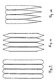
Fig. 9, 10 und 11 zeigen verschiedene Querschnittsformen von erfindungsgemäß einsetzbaren Gitterlamellen in Durchströmrichtung des Gitters.9, 10 and 11 show different cross-sectional shapes of the invention insertable louvres in the flow direction of the grille.
Claims (5)
- Process for preparing foamed materials from two-component reactive plastics materials using carbon dioxide as blowing agent by mixing at least one of the reactive components with carbon dioxide under pressure, with the generation of a mixture containing liquid carbon dioxide, mixing with the other reactive component, expansion and curing of the plastics material, wherein the second mixture containing carbon dioxide is expanded by means of a slotted grating with sub-division into a large number of individual flows at rates of shear of above 500/sec.
- Apparatus for the discharge of a two-component reactive plastics material mixture for foaming and containing liquid carbon dioxide into a mould or onto a conveyor belt, containing at least one slotted grating with narrow slot width.
- Apparatus according to claim 2, wherein the slotted grating exhibits slot widths of 0.05 to 1.5 mm.
- Apparatus according to claim 3, wherein the expansion of the slots in flow direction comes to 50 to 300 times the slot width.
- Apparatus according to one of claims 2 to 4, wherein the clear width of the grating comes to 5 to 30% of the grating cross-sectional area.
Priority Applications (1)
| Application Number | Priority Date | Filing Date | Title |
|---|---|---|---|
| SI9530521T SI0804328T1 (en) | 1994-07-18 | 1995-07-05 | Process and device for preparing foam using carbon dioxide dissolved under pressure |
Applications Claiming Priority (5)
| Application Number | Priority Date | Filing Date | Title |
|---|---|---|---|
| DE4425319 | 1994-07-18 | ||
| DE4425319A DE4425319A1 (en) | 1994-07-18 | 1994-07-18 | Polymer foam mfr. using carbon di:oxide blowing agent and process appts. |
| DE19944445790 DE4445790A1 (en) | 1994-12-21 | 1994-12-21 | Preparation of foamed material using carbon di:oxide as expanding agent |
| DE4445790 | 1994-12-21 | ||
| PCT/EP1995/002604 WO1996002376A1 (en) | 1994-07-18 | 1995-07-05 | Process and device for preparing foam using carbon dioxide dissolved under pressure |
Publications (2)
| Publication Number | Publication Date |
|---|---|
| EP0804328A1 EP0804328A1 (en) | 1997-11-05 |
| EP0804328B1 true EP0804328B1 (en) | 2001-10-17 |
Family
ID=25938451
Family Applications (1)
| Application Number | Title | Priority Date | Filing Date |
|---|---|---|---|
| EP95924975A Expired - Lifetime EP0804328B1 (en) | 1994-07-18 | 1995-07-05 | Process and device for preparing foam using carbon dioxide dissolved under pressure |
Country Status (6)
| Country | Link |
|---|---|
| EP (1) | EP0804328B1 (en) |
| AU (1) | AU2927295A (en) |
| DE (1) | DE59509728D1 (en) |
| ES (1) | ES2164158T3 (en) |
| PT (1) | PT804328E (en) |
| WO (1) | WO1996002376A1 (en) |
Families Citing this family (5)
| Publication number | Priority date | Publication date | Assignee | Title |
|---|---|---|---|---|
| CN1076266C (en) * | 1995-07-11 | 2001-12-19 | 比梅奇集团有限公司 | Apparatus and process for producing polymeric foam |
| US5830393A (en) * | 1996-07-10 | 1998-11-03 | Mitsui Chemicals, Inc. | Process for preparing expanded product of thermoplastic resin |
| WO1998008667A2 (en) * | 1996-08-27 | 1998-03-05 | Trexel, Inc. | Method and apparatus for microcellular polymer extrusion |
| DE10030384A1 (en) | 2000-06-21 | 2002-01-03 | Hennecke Gmbh | Process for the production of block foam |
| DE102011050014A1 (en) | 2011-04-29 | 2012-10-31 | Bayer Materialscience Aktiengesellschaft | Polyurethane foam and process for its preparation |
Citations (1)
| Publication number | Priority date | Publication date | Assignee | Title |
|---|---|---|---|---|
| EP0767728A1 (en) * | 1994-06-28 | 1997-04-16 | Bayer Ag | Method and device for the production of foam using carbon dioxide dissolved under pressure |
Family Cites Families (8)
| Publication number | Priority date | Publication date | Assignee | Title |
|---|---|---|---|---|
| DE1235566B (en) * | 1962-04-30 | 1967-03-02 | Huels Chemische Werke Ag | Device for extrusion of foam profiles |
| US3833202A (en) * | 1972-12-07 | 1974-09-03 | American Polymers | Pre-die chamber for extrusion apparatus |
| JPS53124575A (en) * | 1977-04-07 | 1978-10-31 | Hitachi Chem Co Ltd | Manufacture of polyolefin foam |
| US4337318A (en) * | 1980-09-30 | 1982-06-29 | Doyle Earl N | Process for the total pre-expansion of polyurethane foam |
| US5055272A (en) * | 1989-01-13 | 1991-10-08 | Sealed Air Corporation | Method for producing polyurethane foam and apparatus therefor |
| EP0587581A1 (en) * | 1991-03-25 | 1994-03-23 | The Dow Chemical Company | Nondistorted polyolefin foam structures and process for making |
| US5356565A (en) * | 1992-08-26 | 1994-10-18 | Marathon Oil Company | In-line foam generator for hydrocarbon recovery applications and its use |
| US5308879A (en) * | 1992-09-07 | 1994-05-03 | Nippon Gohsei Kagaku Kogyo Kabushiki Kaisha | Process for preparing biodegradable resin foam |
-
1995
- 1995-07-05 AU AU29272/95A patent/AU2927295A/en not_active Abandoned
- 1995-07-05 ES ES95924975T patent/ES2164158T3/en not_active Expired - Lifetime
- 1995-07-05 PT PT95924975T patent/PT804328E/en unknown
- 1995-07-05 WO PCT/EP1995/002604 patent/WO1996002376A1/en not_active Ceased
- 1995-07-05 EP EP95924975A patent/EP0804328B1/en not_active Expired - Lifetime
- 1995-07-05 DE DE59509728T patent/DE59509728D1/en not_active Expired - Fee Related
Patent Citations (1)
| Publication number | Priority date | Publication date | Assignee | Title |
|---|---|---|---|---|
| EP0767728A1 (en) * | 1994-06-28 | 1997-04-16 | Bayer Ag | Method and device for the production of foam using carbon dioxide dissolved under pressure |
Also Published As
| Publication number | Publication date |
|---|---|
| PT804328E (en) | 2002-04-29 |
| WO1996002376A1 (en) | 1996-02-01 |
| DE59509728D1 (en) | 2001-11-22 |
| ES2164158T3 (en) | 2002-02-16 |
| EP0804328A1 (en) | 1997-11-05 |
| AU2927295A (en) | 1996-02-16 |
Similar Documents
| Publication | Publication Date | Title |
|---|---|---|
| DE4422568C1 (en) | Process and device for foam production using carbon dioxide dissolved under pressure | |
| EP0907478B1 (en) | Process for foam production using dissolved under pressure carbon dioxide | |
| DE3930847C2 (en) | ||
| EP0719627B1 (en) | Process and device for producing foam using carbon dioxide dissolved under pressure | |
| DE19620991A1 (en) | Process and device for foam production using carbon dioxide dissolved under pressure | |
| EP0689920A2 (en) | Method and apparatus for the continuous production of foam plastic blocks or sheets | |
| EP0804328B1 (en) | Process and device for preparing foam using carbon dioxide dissolved under pressure | |
| EP0777564B1 (en) | Process and device for preparing foam using carbon dioxide dissolved under pressure | |
| DE19627065A1 (en) | Process and device for foam production using carbon dioxide dissolved under pressure | |
| DE4425319A1 (en) | Polymer foam mfr. using carbon di:oxide blowing agent and process appts. | |
| DE4019202A1 (en) | Low-density extruded thermoplastic foam - is mfd. by melt-extruding mixt. of plastic and pore regulator, using nitrogen gas and liq. halohydrocarbon as prim. and sec. blowing agents | |
| DE3921523C1 (en) | ||
| DE4220998C1 (en) | Process for making integral foam | |
| DE4445790A1 (en) | Preparation of foamed material using carbon di:oxide as expanding agent | |
| DE4425317A1 (en) | Polymer foam mfr. | |
| WO2003064236A1 (en) | Method for producing polyurethane foam with a variable cell structure | |
| DE4442254A1 (en) | Foam prodn. by dissolving carbon di:oxide in a two-component e.g. polyurethane mixt. | |
| DE2056322A1 (en) | Process for the production of substantially borrowed surface cavity or defect-free polyurethane foam moldings | |
| DE19524434A1 (en) | Foam prodn. from two component reactive plastics - by mixing with carbon di:oxide under pressure and expanding at high shear rate | |
| DE4445789A1 (en) | Foamed material prepn. useful for small evenly distributed bubbles | |
| EP1097034A1 (en) | Method and device for foaming plastics | |
| DE19500198A1 (en) | Foam prodn. from two component reactive plastics | |
| DE4446336A1 (en) | Foam prodn. from two component reactive plastics | |
| DE102005051995A1 (en) | Production of outer skin of low-density polyurethane which consists of expanded polyurethane layer and optional primer-polyurethane layer comprises injecting expanded polyurethane composition over mold surface optionally coated with primer | |
| WO2002004190A1 (en) | Method and device for producing foams |
Legal Events
| Date | Code | Title | Description |
|---|---|---|---|
| PUAI | Public reference made under article 153(3) epc to a published international application that has entered the european phase |
Free format text: ORIGINAL CODE: 0009012 |
|
| 17P | Request for examination filed |
Effective date: 19970429 |
|
| AK | Designated contracting states |
Kind code of ref document: A1 Designated state(s): DE ES FR GB IT PT SE |
|
| AX | Request for extension of the european patent |
Free format text: SI PAYMENT 970429 |
|
| 17Q | First examination report despatched |
Effective date: 19990519 |
|
| GRAG | Despatch of communication of intention to grant |
Free format text: ORIGINAL CODE: EPIDOS AGRA |
|
| GRAG | Despatch of communication of intention to grant |
Free format text: ORIGINAL CODE: EPIDOS AGRA |
|
| GRAH | Despatch of communication of intention to grant a patent |
Free format text: ORIGINAL CODE: EPIDOS IGRA |
|
| GRAH | Despatch of communication of intention to grant a patent |
Free format text: ORIGINAL CODE: EPIDOS IGRA |
|
| GRAA | (expected) grant |
Free format text: ORIGINAL CODE: 0009210 |
|
| AK | Designated contracting states |
Kind code of ref document: B1 Designated state(s): DE ES FR GB IT PT SE |
|
| AX | Request for extension of the european patent |
Free format text: SI PAYMENT 19970429 |
|
| REF | Corresponds to: |
Ref document number: 59509728 Country of ref document: DE Date of ref document: 20011122 |
|
| REG | Reference to a national code |
Ref country code: GB Ref legal event code: IF02 |
|
| GBT | Gb: translation of ep patent filed (gb section 77(6)(a)/1977) |
Effective date: 20011228 |
|
| REG | Reference to a national code |
Ref country code: ES Ref legal event code: FG2A Ref document number: 2164158 Country of ref document: ES Kind code of ref document: T3 |
|
| ET | Fr: translation filed | ||
| REG | Reference to a national code |
Ref country code: PT Ref legal event code: SC4A Free format text: AVAILABILITY OF NATIONAL TRANSLATION Effective date: 20020111 |
|
| PLBE | No opposition filed within time limit |
Free format text: ORIGINAL CODE: 0009261 |
|
| STAA | Information on the status of an ep patent application or granted ep patent |
Free format text: STATUS: NO OPPOSITION FILED WITHIN TIME LIMIT |
|
| 26N | No opposition filed | ||
| PGFP | Annual fee paid to national office [announced via postgrant information from national office to epo] |
Ref country code: PT Payment date: 20030707 Year of fee payment: 9 |
|
| PGFP | Annual fee paid to national office [announced via postgrant information from national office to epo] |
Ref country code: SE Payment date: 20030717 Year of fee payment: 9 |
|
| PG25 | Lapsed in a contracting state [announced via postgrant information from national office to epo] |
Ref country code: SE Free format text: LAPSE BECAUSE OF NON-PAYMENT OF DUE FEES Effective date: 20040706 |
|
| PG25 | Lapsed in a contracting state [announced via postgrant information from national office to epo] |
Ref country code: PT Free format text: LAPSE BECAUSE OF NON-PAYMENT OF DUE FEES Effective date: 20050105 |
|
| REG | Reference to a national code |
Ref country code: SI Ref legal event code: IF |
|
| EUG | Se: european patent has lapsed | ||
| REG | Reference to a national code |
Ref country code: PT Ref legal event code: MM4A Free format text: LAPSE DUE TO NON-PAYMENT OF FEES Effective date: 20050105 |
|
| PGFP | Annual fee paid to national office [announced via postgrant information from national office to epo] |
Ref country code: DE Payment date: 20050611 Year of fee payment: 11 |
|
| PGFP | Annual fee paid to national office [announced via postgrant information from national office to epo] |
Ref country code: GB Payment date: 20050629 Year of fee payment: 11 Ref country code: ES Payment date: 20050629 Year of fee payment: 11 |
|
| REG | Reference to a national code |
Ref country code: SI Ref legal event code: KO00 Effective date: 20050415 |
|
| PGFP | Annual fee paid to national office [announced via postgrant information from national office to epo] |
Ref country code: FR Payment date: 20050718 Year of fee payment: 11 |
|
| PG25 | Lapsed in a contracting state [announced via postgrant information from national office to epo] |
Ref country code: GB Free format text: LAPSE BECAUSE OF NON-PAYMENT OF DUE FEES Effective date: 20060705 |
|
| PGFP | Annual fee paid to national office [announced via postgrant information from national office to epo] |
Ref country code: IT Payment date: 20060731 Year of fee payment: 12 |
|
| PG25 | Lapsed in a contracting state [announced via postgrant information from national office to epo] |
Ref country code: DE Free format text: LAPSE BECAUSE OF NON-PAYMENT OF DUE FEES Effective date: 20070201 |
|
| GBPC | Gb: european patent ceased through non-payment of renewal fee |
Effective date: 20060705 |
|
| REG | Reference to a national code |
Ref country code: FR Ref legal event code: ST Effective date: 20070330 |
|
| REG | Reference to a national code |
Ref country code: ES Ref legal event code: FD2A Effective date: 20060706 |
|
| PG25 | Lapsed in a contracting state [announced via postgrant information from national office to epo] |
Ref country code: ES Free format text: LAPSE BECAUSE OF NON-PAYMENT OF DUE FEES Effective date: 20060706 |
|
| PG25 | Lapsed in a contracting state [announced via postgrant information from national office to epo] |
Ref country code: FR Free format text: LAPSE BECAUSE OF NON-PAYMENT OF DUE FEES Effective date: 20060731 |
|
| PG25 | Lapsed in a contracting state [announced via postgrant information from national office to epo] |
Ref country code: IT Free format text: LAPSE BECAUSE OF NON-PAYMENT OF DUE FEES Effective date: 20070705 |