EP0804123B1 - Tissue repair solder - Google Patents
Tissue repair solder Download PDFInfo
- Publication number
- EP0804123B1 EP0804123B1 EP96900477A EP96900477A EP0804123B1 EP 0804123 B1 EP0804123 B1 EP 0804123B1 EP 96900477 A EP96900477 A EP 96900477A EP 96900477 A EP96900477 A EP 96900477A EP 0804123 B1 EP0804123 B1 EP 0804123B1
- Authority
- EP
- European Patent Office
- Prior art keywords
- solder
- protein
- parts
- tissue
- weight
- Prior art date
- Legal status (The legal status is an assumption and is not a legal conclusion. Google has not performed a legal analysis and makes no representation as to the accuracy of the status listed.)
- Expired - Lifetime
Links
Images


Classifications
-
- A—HUMAN NECESSITIES
- A61—MEDICAL OR VETERINARY SCIENCE; HYGIENE
- A61B—DIAGNOSIS; SURGERY; IDENTIFICATION
- A61B17/00—Surgical instruments, devices or methods, e.g. tourniquets
- A61B17/11—Surgical instruments, devices or methods, e.g. tourniquets for performing anastomosis; Buttons for anastomosis
- A61B17/1128—Surgical instruments, devices or methods, e.g. tourniquets for performing anastomosis; Buttons for anastomosis of nerves
-
- A—HUMAN NECESSITIES
- A61—MEDICAL OR VETERINARY SCIENCE; HYGIENE
- A61L—METHODS OR APPARATUS FOR STERILISING MATERIALS OR OBJECTS IN GENERAL; DISINFECTION, STERILISATION OR DEODORISATION OF AIR; CHEMICAL ASPECTS OF BANDAGES, DRESSINGS, ABSORBENT PADS OR SURGICAL ARTICLES; MATERIALS FOR BANDAGES, DRESSINGS, ABSORBENT PADS OR SURGICAL ARTICLES
- A61L24/00—Surgical adhesives or cements; Adhesives for colostomy devices
- A61L24/04—Surgical adhesives or cements; Adhesives for colostomy devices containing macromolecular materials
- A61L24/10—Polypeptides; Proteins
- A61L24/106—Fibrin; Fibrinogen
-
- A—HUMAN NECESSITIES
- A61—MEDICAL OR VETERINARY SCIENCE; HYGIENE
- A61L—METHODS OR APPARATUS FOR STERILISING MATERIALS OR OBJECTS IN GENERAL; DISINFECTION, STERILISATION OR DEODORISATION OF AIR; CHEMICAL ASPECTS OF BANDAGES, DRESSINGS, ABSORBENT PADS OR SURGICAL ARTICLES; MATERIALS FOR BANDAGES, DRESSINGS, ABSORBENT PADS OR SURGICAL ARTICLES
- A61L31/00—Materials for other surgical articles, e.g. stents, stent-grafts, shunts, surgical drapes, guide wires, materials for adhesion prevention, occluding devices, surgical gloves, tissue fixation devices
- A61L31/04—Macromolecular materials
- A61L31/043—Proteins; Polypeptides; Degradation products thereof
-
- A—HUMAN NECESSITIES
- A61—MEDICAL OR VETERINARY SCIENCE; HYGIENE
- A61B—DIAGNOSIS; SURGERY; IDENTIFICATION
- A61B17/00—Surgical instruments, devices or methods, e.g. tourniquets
- A61B17/00491—Surgical glue applicators
-
- A—HUMAN NECESSITIES
- A61—MEDICAL OR VETERINARY SCIENCE; HYGIENE
- A61B—DIAGNOSIS; SURGERY; IDENTIFICATION
- A61B17/00—Surgical instruments, devices or methods, e.g. tourniquets
- A61B17/00491—Surgical glue applicators
- A61B2017/00513—Tissue soldering
Definitions
- the present invention relates to methods for joining living tissues, including veins, arteries, microvessels, tubes, nerves, organ tissues and biological surfaces, such as peritoneum, omentum, fascia, shin, artificial tissues, and to pharmaceutical products useful in joining these tissues.
- Microsuturing requires considerable skill and is a time consuming procedure. Frequently, tissues which have been joined by microsuturing form considerable scar tissue. Some of the difficulties encountered with microsuturing can be better understood by considering the example of rejoining damaged peripheral nerve tissue.
- peripheral nerves The electrical signals that control the body's organs and transmit information back and forth to the central nervous system (CNS) travel along peripheral nerves.
- the structure of these peripheral nerves is analogous to telephone cables.
- a telephone cable there is a strong protective outer coating that protects all the inner components.
- the copper wires are often grouped in separate insulating tubes that lead to different systems.
- Each of the inner copper wires is a single line that can transmit electricity in either direction and has an insulating coating around it so that it does not interfere with the lines next to it.
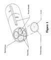
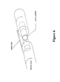
- a peripheral nerve (Figure 1) has an outer membrane consisting of connective tissue such as collagen. This membrane (epineurium) protects and holds the separate nerve bundles together.
- the nerve bundles which lie inside this membrane are called fascicles.
- These fascicles also have a collagen based surrounding membrane and their task is to group together nerve axons supplying a similar area of the body. Inside the fascicle membrane the axons are surrounded by loose connective tissue.
- the axons are a long extension from a cell body which is contained within the CNS in the spine or the brain. Sensory axons transmit to the CNS and motor axons transmit from the CNS. Nerve metabolism is sustained by the vascular system from both outside the nerve and along the centre of the nerve.
- Peripheral nerves can have very small diameters. For instance, the mature median nerve at the wrist is approximately 1 cm in diameter and contains an average of forty fascicles, each of which can contain up to 4500 axons.
- fascicles each of which can contain up to 4500 axons.
- a peripheral nerve When a peripheral nerve is cut all axons distal to the wound change their properties as axon flow is cut off from the cell body. Even when the nerve is reconnected, these axons continue to degenerate distally.
- the Schwann cells which normally wrap themselves around the axons as insulation guide regenerating axons. Joining nerves as accurately as possible by lining up corresponding fascicles enables the axons to more efficiently regenerate.
- peripheral nerve repair uses microsuturing ( Figure 2). This technique requires a dedicated, trained surgeon as microsuturing of just one of the many fascicles with three or more microsutures (using say a 70 micron diameter needle and 30 micron thread) can take very long operating times.
- Microsuturing is at present clinically used where the skills are available. Unfortunately, there are relatively few surgeons who have the necessary manipulative skills for operating at high magnification. Even a reasonable microsuturing technique results in long operating times with added damage to the inner axons due to sutures penetrating the thin insulating perineurial sheath. The use of sutures results in some scarring of the repair due to foreign body reaction. There is also evidence which indicates that in the long term scar tissue formation and scar maturation can lead to impairment of the joined nerve.
- the affected tissue tends to scar and the fibrous tissue that proliferates as a result is a poorer electrical conductor than nerve tissue.
- the bonds formed to date as described in the prior art using laser welding have typically lacked strength. These laser joins alone tend to fail so microsuturing has been used in addition to welding to strengthen these joins.
- WO-A-91/04073 describes laser tissue welding with dye enhanced solders, and uses a viscous solution of fibrinogen for tissue welding.
- WO-A-92/14513 describes filler material for use in tissue welding, specifically preparations of collagen in water containing from 0.5-10% collagen by weight.
- the present invention provides liquid or solid solder compositions (claim 21), their use (claim 1) and their methods of preparation (claim 15).
- solder of the invention is useful in a method for joining tissue comprising:
- the energy transfer can affect the structure of the solder itself leading to bonding within the solder and an enhancement of the strength of the solder and hence the join.
- Drops of solder are typically used where the solder is a fluid solder, and are "painted" across the edges.
- the solder can also be provided as a preformed solid strip.
- the energy source is typically a laser.
- a variety of tissue types can be joined using this method.
- the method is applicable to anastomoses of biological tubes including veins, arteries, lymphatics, nerves, vasa efferentia, fallopian tubes, bile ducts, tubes of the alimentary canal, the ureter, the urethra, tear ducts, bronchi and any other such bodily tubes as well as to repairs of incisions or tears of biological organs such as kidneys, liver or spleen, or of biological surfaces such as the peritoneum and skin. It will therefore be understood that the method can be used in a variety of join situations including the joining of cylindrical anastomoses and the closure of linear defects such as incisions.
- the weld should not be concentrated on the edges being joined as this can damage extruded tissue. Rather, the weld should be distributed across the planar or tubular surface in which the discontinuity lies.
- the repair can additionally comprise the insertion of a thin-walled hollow cylinder of solder inside the tube under repair so that the cylinder spans the severed portions of the tube.
- a thin-walled hollow cylinder of solder inside the tube under repair so that the cylinder spans the severed portions of the tube.
- energy from the energy source is directed through the tube wall to bond the cylinder to the tube ends.
- the cylinder may incorporate a dye, as hereinafter described, to attract energy to the cylinder for more efficient welding.
- the repair is completed by the application of at least one strip or drop of solder across the edges on the outer surface and treating the applied solder as described above.
- the method can also be modified for the repair of other discontinuities in tissue surfaces such as holes, resulting from accident or surgery.
- the solder may be spread or pre-cut to conform to the shape of the repair site, and the edges of the repair site may not need to be aligned or abutted for the repair to be effected.
- a typical nerve repair using the method of the invention is one in which the edges are ends of a cut peripheral nerve fascicle that are to be joined together or an end of a nerve fascicle and the fascicle of substitute nerve graft material. This latter situation is particularly applicable where nerve repair is required but a section of the nerve under repair has been severely damaged or is unavailable, so that the available ends of the fascicle are too remote from each other to be directly joined.
- the actual nature of the damage sustained by the nerve and whether the repair is a primary or secondary repair are factors affecting recovery but in any case the edges of nerve fascicles to be joined are cleanly cut at right angles prior to joining.
- solder as a strip or strips, with space between for natural co-aptation of the surfaces themselves permits the nerve under repair to revascularise. Circumferential welding, by comparison, can inhibit the body's natural healing process and so slow down blood capillary access needed for the area of repair. Laser soldering and suturing techniques ultimately rely on the body regenerating connective tissue to hold the nerve together after either solder or suture connections break down and are replaced by the healing process.
- the present inventors have shown in in vivo experiments that successful regeneration can be achieved by the methods of the present invention without restriction on surrounding tissue movement after the operation. In the case of nerve repair operation on human patients it is routine to initially restrict the movements of the joints of the operated limbs to assist in reducing tension across the repair site.
- Typical biodegradable, biological solders useful in the method of the invention include protein solders.
- Analogues of biological, biodegradable polypeptides useful in the invention include synthetic polypeptides and other molecules capable of forming a viscous "glue" that does not react adversely within the tissue undergoing repair.
- the protein solder may be a solid or a fluid solder composition.
- Fluid protein solder compositions useful in strip welding typically comprise between 100 and 120 mass % of protein relative to water.
- fluid protein solders comprise between 100 and 110 mass % protein relative to water.
- the fluid solder strip is typically 50 to 200 ⁇ m in thickness. Its length is selected to suit the join to be formed but typically is of the order of 2 to 3 mm in length. It is typically painted across the join.
- Solid protein solder compositions useful in strip welding typically comprise between 120 and 230 mass % protein relative to water.
- the strip comprises 170 to 230 mass % protein and more preferably about 210 mass %.
- the solid protein solder composition is provided as a preformed strip.
- Solid solder strips are easier to manipulate than fluid solders. Under the moist conditions inherent in surgery fluid solders may run making it difficult to laser denature the solder before it has spread.
- the solid solder strips can have a paste like or more rigid consistency. They are typically placed across the join with microforceps.
- the solder strips will be substantially rectangular in shape. However, different shape strips may be required in different repair situations. It may also be desirable to provide a plurality of strips joined together for efficient repair of a large or a substantial number of repair sites.
- the protein solder may comprise a single protein of which albumin is a typical example or alternatively the solder may comprise more than one protein.
- Albumin has desirable qualities for solid solder strip formation since it has a high proportion of ⁇ sheet structure which gives rigidity to the strips.
- Fibrin is another example of a protein with significant ⁇ sheet structure. Incorporation of ⁇ helical protein in the solder can assist in making the strips more malleable and thus retain a flatter profile which is particularly well suited for joining nerve ends.
- An example of a suitable proportion of ⁇ helical protein is between 1 and 10% by weight of the protein used. About 5% is a preferred amount.
- Collagen, tropoelastin and elastin are examples of suitable ⁇ helical proteins.
- Protein used in the solder is selected to minimise the risk of adverse host reactions and should therefore preferably be an autologous protein for the host or a foreign protein of low antigenicity.
- the proteins may be obtained from any suitable source. Recombinantly or synthetically produced proteins as well as purified naturally occurring proteins may be used.
- the composition when the solder is to be used with a laser which produces energy at a suitable wavelength the composition includes a substance, such as a dye, which absorbs energy at the wavelength produced by the laser with which the solder is to be used. It is preferable to choose the combination such that the dye or other substance absorbs the energy transmitted by the laser efficiently but the underlying tissue to be joined absorbs the transmitted energy poorly.
- the dye or other substance assists in making the welding specific to the solder used which in turn assists in minimising accidental tissue heating damage to the underlying tissue.
- Dyes which contrast with the tissues being repaired can also be useful in making the solder easier to see.
- An example of a dye with this property is indocyanine green.
- the laser used is a CO 2 laser
- a dye will not assist the energy transfer, as the energy transfer is by water absorption.
- the energy provided by the energy source should be sufficient to bond the solder to form the weld while minimising damage to the underlying tissue.
- the temperature required to denature a protein solder is typically at least 50°C and may exceed 100°C. A preferred range is 50° to 90°C. A particularly preferred range is 80° to 90°C.
- the time of treatment for each join to be effected can vary depending on such factors as ambient conditions, altitude, and of course the nature of the tissue to be joined.
- the duration of treatment is typically short.
- a 30 second passage for laser treatment of a 0.4 mg strip is an example of the time involved although it will be understood that shorter or longer treatment times could be required. It will be understood that solid solder takes longer to denature than fluid solder.
- the present invention provides a protein tissue solder composition
- a protein tissue solder composition comprising water soluble protein and a suitable warer-containing solvent for the protein.
- the present invention provides a kit for use in joining tissues comprising, in a preferably sterile pack, a plurality of protein tissue solder strips and/or shapes of the second aspect of the invention. Preferably a plurality of strip lengths and/or shape sizes are included in the pack.
- the kit preferably includes means for sterile manipulation of the strips.
- the kit also preferably includes means for measuring the strips.
- the kit may also comprise an energy source such as a fibre coupled laser system.
- Tissue repair is performed using a laser to activate a protein solder applied across the tissue edges to be joined. This solder denatures upon laser irradiation and bonds with itself and the neighbouring membrane to form the join.
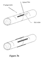
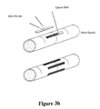
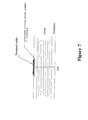
- the procedure is shown schematically in Figures 3 and 7 for a repair to a nerve fascicle. The solder is applied in longitudinal strips across the join.
- Repair to severed nerve tissues is effected by the placement of solder across the severed edges and exposure of the solder to laser as described above.
- solder In order to repair nerve tissue without damage to the contents of the nerve it is desirable to avoid concentrating the weld on the edges as extruded nerve contents may be damaged. Rather the weld should be distributed across the planar or tubular surface in which the discontinuity lies.
- peritoneum planes of tissue in which joins without sutures can be achieved by the application of solder across the discontinuities to be joined and welding as described above. In this case it is less important to avoid concentration of welding on the edges.
- a GaAs/GaAlAs laser diode with a nominal power of 250 mW (Spectra Diode Labs, San Jose, California) is used.
- the laser light is coupled into a 100 ⁇ m diameter core optical fibre which is hand held in a fibre chuck.
- the diode is operated in continuous mode at 75 mW during the laser soldering. Because this laser is Class 3b, and is not eye safe, protective glasses must be worn at all times when using this laser.
- a suitable protein solder is a mixture of water, albumin and indocyanine green (ICG) dye (Becton Dickinson, Missouri). Indocyanine green has a maximum absorption coefficient at a wavelength of 805 nm of 2 x 10 5 M -1 cm -1 .
- the percentages of albumin and dye compared to the water were 110% and 0.6% respectively for fluid solder. 210% albumen was used in preparing solder strips. It is notable that ICG dye appears to preferentially bind with the albumin ensuring that heat is efficiently transferred to denature the protein solder.
- tissue edges are prepared in accordance with standard techniques for the tissue type and geometry of the repair.
- micro forceps the edges are aligned and butted together.
- a 2 mm long stripe of fluid solder is "painted" longitudinally across the junction of the edges using a 30 gauge needle freshly coated in the solder.
- a strip solder is laid across the join using microforceps.
- the solid strip repair method is simpler.
- a solid strip is held in special microforceps and placed across the junction parallel to the length of the structures to be joined.
- the laser output is then directed at the solid strip and the solid solder changes colour signalling denaturation which causes it to adhere to the underlying tissue membrane. The process is repeated with further strips to ensure a strong union of surface.
- the diode laser output from the 100 ⁇ m optical fibre is then used in a 30 second continuous pass to denature solid solder into a strip weld.
- the solid solder strip turns brown on the surface and opaque underneath from the single pass, signalling denaturation.
- a two second laser pass can be sufficient to denature the fluid solder.
- a second layer of fluid solder is applied to the strip in order to increase the strength of the weld and the two second laser pass is repeated.
- the gauze under the join is then used with the micro-forceps to rotate the join so that other strips can be applied.
- the resulting strips were between 50 and 100 ⁇ m in thickness, about 0.6 mm wide and 1.5 to 3.5 mm long. It will be understood that where the strips are used in mending nerve fascicles that the desired width and length are dictated by fascicle dimensions.
- the width, thickness and length mentioned here are those suitable for use with a rat tibial nerve which has a diameter of 0.2 to 0.8 mm.
- the ratio of strip width to nerve circumference is typically:
- a 100 ⁇ m core optical fibre-coupled 75 mW diode laser operating at a wavelength of 800 nm has been used in conjunction with a protein solder to stripe weld severed rat tibial nerves, reducing the long operating time required for microsurgical nerve repair.
- CMAP Compound Muscle Action Potential
- a GaAs/GaAlAs laser diode with a nominal power of 250 mW (Spectra Diode Labs, San Jose, California) was used.
- the laser light was coupled into a 100 ⁇ m diameter core optical fibre which was hand held in a fibre chuck.
- the diode laser was mounted on a heat sink, and the diode current and temperature were controlled by a SDL-800 diode driver.
- the diode was operated in continuous mode at 75 mW during the laser soldering, corresponding to a maximum power density of 955 W/cm at the tissue.
- the laser output power was measured with a Scientech (Boulder, Colorado) power meter. Because this laser is Class 3b, and is not eye safe, protective glasses were worn at all times when using this laser.
- the solder used in this study was an albumin based protein mixture, also containing indocyanine green (ICG) dye (Becton Dickinson, Missouri). Indocyanine green has a maximum absorption coefficient at a wavelength of 805 nm of 2 x 10 5 M -1 cm -1 . It is notable that this dye appears to preferentially bind with the proteins ensuring that heat is efficiently transferred to denature the protein solder.
- ICG indocyanine green
- the tibial nerve was then severed with serrated micro-scissors and left for 3 minutes for the normal extrusion of axoplasm to occur. This was then trimmed with the serrated micro-scissors as required, after which the nerve was repaired with either four laser solder strips or four 10-0 perineurial sutures.
- the laser solder method involved aligning both stumps of the severed nerve with micro-forceps then a 2 mm long strip of solder was "painted" longitudinally across the junction of the severed ends using a 30 gauge needle freshly coated in the solder (Figure 3a).
- the diode laser output from the 100 ⁇ m optical fibre was then used in a continuous two second pass to denature the solder into a strip weld.
- the solder was observed to turn brown on the surface and opaque underneath from the single pass, signalling denaturation.
- a second layer of solder was applied to the strip and the two second laser pass was repeated.
- the gauze under the nerve was then used with the micro-forceps to rotate the nerve so that three other two layered stripes could be applied, each approximately 90° apart.
- the anastomosis site of the tibial nerves were fixed in 5% formalin, alcohol dehydrated, imbedded in paraffin, longitudinally sectioned and stained with either Masson's trichrome or Giemsa.
- the rats were reanaesthetised using the method described in section 3.
- the site was exposed and the anastomosis of the tibial nerve observed.
- the two other branches of the sciatic nerve, the peroneal and sural nerves were then severed so that only the tibial nerve branch of the sciatic nerve could conduct electrical stimulation of the sciatic nerve to the muscles of the hind foot.
- Two days later the rats were positioned on their side and insulated from the table by a folded surgical drape. An infrared lamp was used to maintain their rectal temperature above 36°C.
- a clinical electromyograph (Cadwell Sierra EMG/EP) was used for stimulation and recording.
- Two 25 gauge stimulating electrodes were placed 10mm apart on each side of the sciatic nerve above the sciatic notch, near the hip. The nerve was activated using rectangular pulses (0.1 to 0.3 ms; 0 to 30 mA; 1 Hz).
- Compound muscle action potentials (CMAPs) were recorded from the plantar muscles of the foot in response to supramaximal stimulation of the sciatic nerve.
- a set of three recording electrodes were used.
- a 25 gauge ground electrode was inserted subcutaneously between the stimulating and recording electrodes 1,2 .
- a 30 gauge reference electrode was inserted into the heel pad and a 30 gauge recording electrode was inserted into the plantar muscles of the foot .
- the CMAPs were recorded and processed to determine their negative wave peak value.
- FIG. 5b A section showing the effect of microsuturing nerve fascicles using 10/0-nylon is shown in Figure 5b. This section stained with Giemsa, displays axon extrusion at the join, as well as localised perineurial and axonal damage due to the suture.
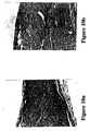
- Histopathology at 3 months shows regeneration of myelinated axons in laser nerve repairs (Figure 10a), with no discontinuity of either the fibers and their sheaths, or the fibrous perineurium. No evidence is seen of inflammation or myelin phagocytosis. Full restoration, as assessed by light microscopy, of the histologic integrity of the tibial nerve has been achieved by the laser weld.
- the sutured nerves also show successfull anastomosis with myelinated axon regeneration, however, it is still evident that the nylon thread is surrounded by fibrous tissue, which creates an obstacle to the directionality of the regenerated axons ( Figure 10b).
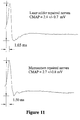
- the electrophysiological measurements of the in vivo study were performed on twenty-four laser solder repaired rats and thirteen microsuture repaired rats having three months recovery. Of this group all twenty-four laser solder anastomoses were patent as were the thirteen microsuture anastomoses.
- the average amplitude of the muscle action potentials, resulting from supramaximal stimulation of the nerve above the repair site was 2.4 +/- 0.7 mV for the twenty-four laser soldered tibial nerves and 2.7 +/- 0.8 mV for the thirteen microsutured nerves.
- the normal muscle action potential produced by stimulating the tibial nerve supramaximally was recorded at 8.7 ⁇ 3 mV from ten rats ( Figure 11).
- the present invention has application in the field of surgery where it is of application in joining together tissue edges, in end to end, side to end and side to side applications.
Abstract
Description
- Composition:
-
- Albumin (fraction V powder from Sigma, St. Louis, Missouri) at least 100 % to 110% by weight compared to water.
- Indocyanine Green (Becton Dickinson, Missouri) approximately 0.6% by weight compared to water.
- Water (injection grade)
- Procedure:
- A solution of ICG in water was prepared in a minitube. The albumin was added to the tube. The albumin and solution were mixed using a vortex mixer. This causes the protein structure to change leading to linkage of protein molecules to each other rather than to water molecules.
- Composition:
-
- Albumin (fraction V powder from Sigma, St. Louis, Missouri) 210% by weight compared to water
- Indocyanine Green (Becton Dickinson, Missouri) approximately 0.6% by weight compared to water
- Water (injection grade)
- Procedure:
- The ICG was dissolved in the water and the albumin was added to this solution in a minitube. This combination was mixed using a vortex mixer and a needle. The combination was mixed (for approximately 3 minutes) until it became a homogenous, malleable, green paste. The phase of the mixture changed under this mixing technique to provide an almost solid composition with mainly protein to protein linkages rather than protein to water linkages. The system is no longer a solution at this stage. The protein paste was malleable and could be cut into strips for up to about 30 minutes after mixing. After this time the paste hardened due to dehydration and became too hard to cut.
Claims (33)
- Use of either 100-120 parts by weight water soluble protein per 100 parts by weight water in a water-containing solvent, in the manufacture of a fluid, biodegradable, biological solder for joining tissue, or 120-230 parts by weight water soluble protein per 100 parts by weight water in a water-containing solvent in the manufacture of a substantially solid biodegradable, biological solder for joining tissue.
- Use according to Claim 1 wherein the tissue is nerve tissue.
- Use according to Claim 1 wherein the joining tissue is an anastomosis of a biological tube including veins, arteries, lymphatic, vasa efferentia, fallopian tubes, bile ducts, tubes of the alimentary canal, the ureter, the urethra, tear ducts or bronchi.
- Use according to Claim 1 wherein the joining tissue is a repair of an incision or tear of a biological organ including kidneys, liver or spleen, or of a biological surface such as the peritoneum or skin.
- Use according to any one of Claims 1 to 4 wherein the solder incorporates a substance which absorbs energy from an energy source highly compared to absorption of the energy by the tissue.
- Use according to Claim 5, wherein the substance is a dye.
- Use according to Claims 5 or 6 wherein the energy source is a laser.
- Use according to any of Claims 1 to 7 of 100-120 parts by weight protein per 100 parts by weight solvent.
- Use according to any of Claims 1 to 7 of 120-230 parts by weight protein per 100 parts by weight solvent.
- Use according to any of Claims 1 to 9 wherein the solvent is water.
- Use according to any preceding claim, wherein the protein is albumin.
- Use according to any preceding claim, wherein the protein contains (β-sheet structure.
- Use according to Claim 12, wherein the β-sheet structure imparts rigidity to the solder.
- Use according to any preceding claim, wherein the protein has between 1 and 10% by weight α helical content.
- A method of making a biodegradable, biological solder for joining tissue, comprising mixing either 100-120 parts by weight water soluble protein with 100 parts by weight water in a water-containing solvent, said solder being fluid, or 120-230 parts by weight water soluble protein with 100 parts by weight water in a water-containing solvent, said solder being substantially solid.
- A method according to Claim 15, wherein the solder further comprises a substance which absorbs energy from an energy source highly compared to absorption of the energy by the tissue.
- A method according to Claim 16 wherein the substance is a dye.
- A method according to Claim 16 or 17 wherein the energy source is a laser.
- A method according to any of Claims 15 to 18 for making a fluid tissue solder comprising mixing 100-120 parts by weight protein with 100 parts by weight solvent.
- A method according to any of Claims 15 to 18 for making a solid tissue solder comprising mixing 120-230 parts by weight protein with 100 parts by weight solvent.
- A fluid protein tissue solder composition comprising 100 to 120 parts by weight water soluble protein per 100 parts by weight water in a water containing solvent.
- A protein tissue solder composition according to Claim 21 comprising 100 to 110 parts by weight protein.
- A substantially solid protein tissue solder comprising 120 to 230 parts by weight water soluble protein per 100 parts by weight water in a water containing solvent.
- A protein solder according to Claim 23 comprising 170 to 230 parts by weight protein.
- A protein solder according to Claim 24 comprising about 210 parts by weight protein.
- A protein solder according to any of Claims 21-25, wherein the solvent is water.
- A protein solder composition according to any of Claims 21-26 further comprising a substance which absorbs energy from an energy source highly compared to absorption of the energy by the tissue.
- A protein solder composition according to Claim 27 wherein the substance is a dye.
- A protein solder according to any of Claims 21-28 wherein the protein is albumin.
- A substantially solid protein solder according to Claim 23 wherein the protein contains β-sheet structure.
- A substantially solid protein solder according to Claim 30, wherein the β-sheet structure imparts rigidity to the solder.
- A substantially solid protein solder according to Claim 30 wherein the protein has between 1 and 10% by weight α helical content.
- A kit for joining tissues comprising, in a preferably sterile pack, a plurality of strips and/or shapes of a protein solder according to any one of Claims 21 to 32.
Applications Claiming Priority (4)
| Application Number | Priority Date | Filing Date | Title |
|---|---|---|---|
| AUPN066795 | 1995-01-20 | ||
| AUPN0667A AUPN066795A0 (en) | 1995-01-20 | 1995-01-20 | Method of repair |
| AUPN0667/95 | 1995-01-20 | ||
| PCT/AU1996/000024 WO1996022054A1 (en) | 1995-01-20 | 1996-01-19 | Method of tissue repair |
Publications (3)
| Publication Number | Publication Date |
|---|---|
| EP0804123A1 EP0804123A1 (en) | 1997-11-05 |
| EP0804123A4 EP0804123A4 (en) | 1999-01-07 |
| EP0804123B1 true EP0804123B1 (en) | 2003-05-28 |
Family
ID=3785053
Family Applications (1)
| Application Number | Title | Priority Date | Filing Date |
|---|---|---|---|
| EP96900477A Expired - Lifetime EP0804123B1 (en) | 1995-01-20 | 1996-01-19 | Tissue repair solder |
Country Status (11)
| Country | Link |
|---|---|
| US (3) | US6211335B1 (en) |
| EP (1) | EP0804123B1 (en) |
| JP (1) | JPH11501825A (en) |
| AT (1) | ATE241319T1 (en) |
| AU (1) | AUPN066795A0 (en) |
| CA (1) | CA2210894A1 (en) |
| DE (1) | DE69628408T2 (en) |
| ES (1) | ES2201167T3 (en) |
| HK (1) | HK1003613A1 (en) |
| NZ (1) | NZ298721A (en) |
| WO (1) | WO1996022054A1 (en) |
Cited By (1)
| Publication number | Priority date | Publication date | Assignee | Title |
|---|---|---|---|---|
| DE102012008703A1 (en) | 2012-04-13 | 2013-10-17 | Bernhard Franz | Device for restoring function of severed and/or injured nerve e.g. sciatica nerve in brain and spinal cord of human, irradiates beams to nerve ends by miniature probe such that associated severed axon ends are irradiated |
Families Citing this family (66)
| Publication number | Priority date | Publication date | Assignee | Title |
|---|---|---|---|---|
| AUPN066795A0 (en) * | 1995-01-20 | 1995-02-16 | Macquarie Research Limited | Method of repair |
| WO1998036707A1 (en) * | 1997-02-07 | 1998-08-27 | Sisters Of Providence In Oregon | Method of producing biomaterials |
| US5929044A (en) * | 1997-08-14 | 1999-07-27 | Cornell Research Foundation | Protein solder composition and method of use |
| WO1999051282A1 (en) * | 1998-04-06 | 1999-10-14 | Cornell Research Foundation, Inc. | Composition for tissue welding and method of use |
| AU768533C (en) * | 1998-06-18 | 2005-12-08 | Macquarie Research Limited | Method of tissue repair II |
| AUPP421498A0 (en) * | 1998-06-18 | 1998-07-09 | Macquarie Research Limited | Method of tissue repair |
| EP1105167A1 (en) * | 1998-08-21 | 2001-06-13 | Tissuemed Limited | Activatable sheet for topical, therapeutic use |
| US6626899B2 (en) | 1999-06-25 | 2003-09-30 | Nidus Medical, Llc | Apparatus and methods for treating tissue |
| US6680063B1 (en) | 1999-10-08 | 2004-01-20 | Providence Health System-Oregon | Biocompatible albumin lamina and method |
| GB0002719D0 (en) * | 2000-02-08 | 2000-03-29 | Tissuemed Ltd | Thermal ablation of tissue |
| US6296607B1 (en) * | 2000-10-20 | 2001-10-02 | Praxis, Llc. | In situ bulking device |
| US7033348B2 (en) * | 2001-04-10 | 2006-04-25 | The Research Foundation Of The City University Of New York | Gelatin based on Power-gel™ as solders for Cr4+laser tissue welding and sealing of lung air leak and fistulas in organs |
| ATE519438T1 (en) | 2001-09-26 | 2011-08-15 | Rice University | OPTICALLY ABSORBING NANOPARTICLES FOR IMPROVED TISSUE REPAIR |
| US8501165B2 (en) * | 2001-12-12 | 2013-08-06 | Promethean Surgical Devices Llc | In situ bonds |
| US6723095B2 (en) * | 2001-12-28 | 2004-04-20 | Hemodynamics, Inc. | Method of spinal fixation using adhesive media |
| US7257450B2 (en) * | 2003-02-13 | 2007-08-14 | Coaptus Medical Corporation | Systems and methods for securing cardiovascular tissue |
| US8021359B2 (en) * | 2003-02-13 | 2011-09-20 | Coaptus Medical Corporation | Transseptal closure of a patent foramen ovale and other cardiac defects |
| WO2004087235A2 (en) * | 2003-03-27 | 2004-10-14 | Cierra, Inc. | Methods and apparatus for treatment of patent foramen ovale |
| US7293562B2 (en) * | 2003-03-27 | 2007-11-13 | Cierra, Inc. | Energy based devices and methods for treatment of anatomic tissue defects |
| US8021362B2 (en) * | 2003-03-27 | 2011-09-20 | Terumo Kabushiki Kaisha | Methods and apparatus for closing a layered tissue defect |
| US7186251B2 (en) | 2003-03-27 | 2007-03-06 | Cierra, Inc. | Energy based devices and methods for treatment of patent foramen ovale |
| US7165552B2 (en) * | 2003-03-27 | 2007-01-23 | Cierra, Inc. | Methods and apparatus for treatment of patent foramen ovale |
| US7972330B2 (en) | 2003-03-27 | 2011-07-05 | Terumo Kabushiki Kaisha | Methods and apparatus for closing a layered tissue defect |
| US6939348B2 (en) | 2003-03-27 | 2005-09-06 | Cierra, Inc. | Energy based devices and methods for treatment of patent foramen ovale |
| US7311701B2 (en) * | 2003-06-10 | 2007-12-25 | Cierra, Inc. | Methods and apparatus for non-invasively treating atrial fibrillation using high intensity focused ultrasound |
| WO2005055958A2 (en) * | 2003-12-09 | 2005-06-23 | Promethean Surgical Devices Llc | Improved surgical adhesive and uses therefor |
| JP4793651B2 (en) * | 2004-02-20 | 2011-10-12 | 学校法人慶應義塾 | Sheath removal hole closing device using laser welding |
| US7976539B2 (en) | 2004-03-05 | 2011-07-12 | Hansen Medical, Inc. | System and method for denaturing and fixing collagenous tissue |
| US7367975B2 (en) | 2004-06-21 | 2008-05-06 | Cierra, Inc. | Energy based devices and methods for treatment of anatomic tissue defects |
| US7473252B2 (en) * | 2004-10-07 | 2009-01-06 | Coaptus Medical Corporation | Systems and methods for shrinking and/or securing cardiovascular tissue |
| US20060111698A1 (en) * | 2004-11-22 | 2006-05-25 | Kihong Kwon | Apparatus and method for performing laser-assisted vascular anastomoses |
| CA2599310C (en) * | 2005-04-11 | 2013-12-10 | Cierra, Inc. | Methods and apparatus to achieve a closure of a layered tissue defect |
| WO2007030892A1 (en) * | 2005-09-15 | 2007-03-22 | Avastra Ltd | Method of tissue repair iii |
| US20070093805A1 (en) * | 2005-10-17 | 2007-04-26 | Coaptus Medical Corporation | Systems and methods for securing cardiovascular tissue, including via asymmetric electrodes |
| US20070255356A1 (en) * | 2006-04-28 | 2007-11-01 | Ondine International, Ltd. | Photodisinfection delivery devices and methods |
| US9079762B2 (en) | 2006-09-22 | 2015-07-14 | Ethicon Endo-Surgery, Inc. | Micro-electromechanical device |
| US9289279B2 (en) * | 2006-10-06 | 2016-03-22 | Promethean Surgical Devices, Llc | Apparatus and method for limiting surgical adhesions |
| US7914552B2 (en) * | 2006-11-09 | 2011-03-29 | Ethicon Endo-Surgery, Inc. | Method of performing an end-to-end anastomosis using a stent and an adhesive |
| WO2008065464A2 (en) * | 2006-11-28 | 2008-06-05 | Universita' Degli Studi Di Padova | A method for the pulmonary aerostasis and a device for its application |
| US20080140069A1 (en) * | 2006-12-07 | 2008-06-12 | Cierra, Inc. | Multi-electrode apparatus for tissue welding and ablation |
| US20080139991A1 (en) * | 2006-12-08 | 2008-06-12 | Ondine International, Ltd. | Method of wound disinfecting and tissue welding |
| US7713265B2 (en) | 2006-12-22 | 2010-05-11 | Ethicon Endo-Surgery, Inc. | Apparatus and method for medically treating a tattoo |
| US8273015B2 (en) | 2007-01-09 | 2012-09-25 | Ethicon Endo-Surgery, Inc. | Methods for imaging the anatomy with an anatomically secured scanner assembly |
| US8801606B2 (en) | 2007-01-09 | 2014-08-12 | Ethicon Endo-Surgery, Inc. | Method of in vivo monitoring using an imaging system including scanned beam imaging unit |
| US8216214B2 (en) | 2007-03-12 | 2012-07-10 | Ethicon Endo-Surgery, Inc. | Power modulation of a scanning beam for imaging, therapy, and/or diagnosis |
| US8626271B2 (en) | 2007-04-13 | 2014-01-07 | Ethicon Endo-Surgery, Inc. | System and method using fluorescence to examine within a patient's anatomy |
| US7995045B2 (en) | 2007-04-13 | 2011-08-09 | Ethicon Endo-Surgery, Inc. | Combined SBI and conventional image processor |
| US20080269205A1 (en) * | 2007-04-27 | 2008-10-30 | Ondine International, Ltd. | Methods to prevent vertical transmission of infectious diseases |
| US20100280545A1 (en) * | 2007-05-10 | 2010-11-04 | Seraffix Ltd. | System and method for bonding living tissue |
| EP2155123A1 (en) * | 2007-05-14 | 2010-02-24 | Promethean Surgical Devices, Llc | Foam prosthesis for spinal disc |
| US8160678B2 (en) | 2007-06-18 | 2012-04-17 | Ethicon Endo-Surgery, Inc. | Methods and devices for repairing damaged or diseased tissue using a scanning beam assembly |
| US7982776B2 (en) | 2007-07-13 | 2011-07-19 | Ethicon Endo-Surgery, Inc. | SBI motion artifact removal apparatus and method |
| US9125552B2 (en) | 2007-07-31 | 2015-09-08 | Ethicon Endo-Surgery, Inc. | Optical scanning module and means for attaching the module to medical instruments for introducing the module into the anatomy |
| US20090035725A1 (en) * | 2007-08-02 | 2009-02-05 | Ondine International, Ltd. | Photodisinfection of oral cavity |
| US7983739B2 (en) | 2007-08-27 | 2011-07-19 | Ethicon Endo-Surgery, Inc. | Position tracking and control for a scanning assembly |
| US7925333B2 (en) | 2007-08-28 | 2011-04-12 | Ethicon Endo-Surgery, Inc. | Medical device including scanned beam unit with operational control features |
| CA2715813C (en) * | 2008-02-13 | 2017-03-21 | Erich Zurfluh | Light delivery device that provides a radial light output pattern |
| US8050520B2 (en) | 2008-03-27 | 2011-11-01 | Ethicon Endo-Surgery, Inc. | Method for creating a pixel image from sampled data of a scanned beam imager |
| US8332014B2 (en) | 2008-04-25 | 2012-12-11 | Ethicon Endo-Surgery, Inc. | Scanned beam device and method using same which measures the reflectance of patient tissue |
| JP5485984B2 (en) * | 2008-05-09 | 2014-05-07 | ザ ジェネラル ホスピタル コーポレーション | Tissue engineering construct |
| WO2010014676A1 (en) | 2008-08-01 | 2010-02-04 | Ondine International Ltd. | Composition and method for treatment of mrsa |
| US20110172704A1 (en) * | 2008-09-19 | 2011-07-14 | The Trustees Of The University Of Pennsylvania | Solder formulation and use in tissue welding |
| WO2010036617A1 (en) * | 2008-09-23 | 2010-04-01 | Ondine International Holdings Ltd. | Portable photodynamic disinfection light delivery device for catheter disinfection |
| US8388613B1 (en) | 2010-04-09 | 2013-03-05 | The United States Of America As Represented By The Administrator Of The National Aeronautics And Space Administration | Methods and apparatus for microwave tissue welding for wound closure |
| WO2011133660A2 (en) * | 2010-04-20 | 2011-10-27 | Alfano Robert R | Method for picosecond and femtosecond laser tissue welding |
| WO2021041696A1 (en) * | 2019-08-30 | 2021-03-04 | Arizona Board Of Regents On Behalf Of Arizona State University | Nerve repair using laser sealing |
Family Cites Families (35)
| Publication number | Priority date | Publication date | Assignee | Title |
|---|---|---|---|---|
| US4281942A (en) * | 1978-11-13 | 1981-08-04 | General Electric Company | Lubrication system for high speed spline connection and bearing |
| US4470776A (en) * | 1979-11-28 | 1984-09-11 | Commercial Shearing, Inc. | Methods and apparatus for gear pump lubrication |
| US4493320A (en) | 1982-04-02 | 1985-01-15 | Treat Michael R | Bipolar electrocautery surgical snare |
| US4672969A (en) | 1983-10-06 | 1987-06-16 | Sonomo Corporation | Laser healing method |
| US5409479A (en) | 1983-10-06 | 1995-04-25 | Premier Laser Systems, Inc. | Method for closing tissue wounds using radiative energy beams |
| US5140984A (en) | 1983-10-06 | 1992-08-25 | Proclosure, Inc. | Laser healing method and apparatus |
| US4854320A (en) | 1983-10-06 | 1989-08-08 | Laser Surgery Software, Inc. | Laser healing method and apparatus |
| US5002051A (en) | 1983-10-06 | 1991-03-26 | Lasery Surgery Software, Inc. | Method for closing tissue wounds using radiative energy beams |
| US4669999A (en) * | 1984-08-22 | 1987-06-02 | Sundstrand Corporation | Lubricant delivering and containment overload shearable coupling |
| US4600533A (en) | 1984-12-24 | 1986-07-15 | Collagen Corporation | Collagen membranes for medical use |
| US4856633A (en) * | 1988-03-31 | 1989-08-15 | Specht Victor J | Wheel hub assembly |
| US4973466A (en) * | 1988-06-21 | 1990-11-27 | Chiron Ophthalmics, Inc. | Wound-healing dressings and methods |
| US4810126A (en) * | 1988-07-05 | 1989-03-07 | Allied-Signal Inc. | Compact oil slinger and spring loaded retention device |
| EP0491794A4 (en) * | 1989-09-12 | 1992-08-19 | The Trustees Of Columbia University In The City Of New York | Laser tissue welding with dye enhanced solders |
| US5071417A (en) | 1990-06-15 | 1991-12-10 | Rare Earth Medical Lasers, Inc. | Laser fusion of biological materials |
| US5292362A (en) * | 1990-07-27 | 1994-03-08 | The Trustees Of Columbia University In The City Of New York | Tissue bonding and sealing composition and method of using the same |
| US5209776A (en) * | 1990-07-27 | 1993-05-11 | The Trustees Of Columbia University In The City Of New York | Tissue bonding and sealing composition and method of using the same |
| US5611794A (en) | 1990-10-11 | 1997-03-18 | Lasersurge, Inc. | Clamp for approximating tissue sections |
| US5156613A (en) | 1991-02-13 | 1992-10-20 | Interface Biomedical Laboratories Corp. | Collagen welding rod material for use in tissue welding |
| US5669934A (en) | 1991-02-13 | 1997-09-23 | Fusion Medical Technologies, Inc. | Methods for joining tissue by applying radiofrequency energy to performed collagen films and sheets |
| WO1992014513A1 (en) * | 1991-02-13 | 1992-09-03 | Interface Biomedical Laboratories Corp. | Filler material for use in tissue welding |
| US5749895A (en) | 1991-02-13 | 1998-05-12 | Fusion Medical Technologies, Inc. | Method for bonding or fusion of biological tissue and material |
| US5334191A (en) | 1992-05-21 | 1994-08-02 | Dix Phillip Poppas | Laser tissue welding control system |
| US5292253A (en) * | 1992-06-22 | 1994-03-08 | Laser Medical Technology, Inc. | Method for repairing tooth and bone tissue |
| US5254113A (en) | 1992-08-31 | 1993-10-19 | Wilk Peter J | Anastomosis method |
| US5330974A (en) * | 1993-03-01 | 1994-07-19 | Fibratek, Inc. | Therapeutic fibrinogen compositions |
| US5552452A (en) * | 1993-03-15 | 1996-09-03 | Arch Development Corp. | Organic tissue glue for closure of wounds |
| ATE169483T1 (en) | 1993-04-28 | 1998-08-15 | Focal Inc | APPARATUS, PRODUCT AND USE RELATING TO INTRALUMINAL PHOTOTHERMOFORMING |
| US5571216A (en) | 1994-01-19 | 1996-11-05 | The General Hospital Corporation | Methods and apparatus for joining collagen-containing materials |
| US5583114A (en) * | 1994-07-27 | 1996-12-10 | Minnesota Mining And Manufacturing Company | Adhesive sealant composition |
| US5662643A (en) | 1994-09-28 | 1997-09-02 | Abiomed R & D, Inc. | Laser welding system |
| AUPN066795A0 (en) * | 1995-01-20 | 1995-02-16 | Macquarie Research Limited | Method of repair |
| US5556414A (en) | 1995-03-08 | 1996-09-17 | Wayne State University | Composite intraluminal graft |
| US5713891A (en) | 1995-06-02 | 1998-02-03 | Children's Medical Center Corporation | Modified solder for delivery of bioactive substances and methods of use thereof |
| US6189411B1 (en) * | 1999-03-03 | 2001-02-20 | American Equipment Company | Rear end gear pump |
-
1995
- 1995-01-20 AU AUPN0667A patent/AUPN066795A0/en not_active Abandoned
-
1996
- 1996-01-19 DE DE69628408T patent/DE69628408T2/en not_active Expired - Fee Related
- 1996-01-19 JP JP8521922A patent/JPH11501825A/en active Pending
- 1996-01-19 AT AT96900477T patent/ATE241319T1/en not_active IP Right Cessation
- 1996-01-19 NZ NZ298721A patent/NZ298721A/en unknown
- 1996-01-19 CA CA002210894A patent/CA2210894A1/en not_active Abandoned
- 1996-01-19 EP EP96900477A patent/EP0804123B1/en not_active Expired - Lifetime
- 1996-01-19 WO PCT/AU1996/000024 patent/WO1996022054A1/en active IP Right Grant
- 1996-01-19 ES ES96900477T patent/ES2201167T3/en not_active Expired - Lifetime
- 1996-01-19 US US08/875,228 patent/US6211335B1/en not_active Expired - Fee Related
-
1998
- 1998-04-08 HK HK98102946A patent/HK1003613A1/en not_active IP Right Cessation
-
2001
- 2001-01-25 US US09/769,585 patent/US6583117B2/en not_active Expired - Fee Related
-
2003
- 2003-06-23 US US10/601,825 patent/US20050079997A1/en not_active Abandoned
Cited By (1)
| Publication number | Priority date | Publication date | Assignee | Title |
|---|---|---|---|---|
| DE102012008703A1 (en) | 2012-04-13 | 2013-10-17 | Bernhard Franz | Device for restoring function of severed and/or injured nerve e.g. sciatica nerve in brain and spinal cord of human, irradiates beams to nerve ends by miniature probe such that associated severed axon ends are irradiated |
Also Published As
| Publication number | Publication date |
|---|---|
| WO1996022054A1 (en) | 1996-07-25 |
| CA2210894A1 (en) | 1996-07-25 |
| NZ298721A (en) | 1999-11-29 |
| HK1003613A1 (en) | 1998-11-06 |
| JPH11501825A (en) | 1999-02-16 |
| DE69628408T2 (en) | 2004-03-11 |
| US6583117B2 (en) | 2003-06-24 |
| ATE241319T1 (en) | 2003-06-15 |
| DE69628408D1 (en) | 2003-07-03 |
| EP0804123A4 (en) | 1999-01-07 |
| EP0804123A1 (en) | 1997-11-05 |
| US6211335B1 (en) | 2001-04-03 |
| AUPN066795A0 (en) | 1995-02-16 |
| US20050079997A1 (en) | 2005-04-14 |
| US20020045732A1 (en) | 2002-04-18 |
| ES2201167T3 (en) | 2004-03-16 |
Similar Documents
| Publication | Publication Date | Title |
|---|---|---|
| EP0804123B1 (en) | Tissue repair solder | |
| US7078378B1 (en) | Method of tissue repair II | |
| Bass et al. | Laser tissue welding: A comprehensive review of current and future | |
| US5669934A (en) | Methods for joining tissue by applying radiofrequency energy to performed collagen films and sheets | |
| Lauto et al. | Laser‐activated solid protein bands for peripheral nerve repair: An in vivo study | |
| US6773699B1 (en) | Light energized tissue adhesive conformal patch | |
| US6939364B1 (en) | Composite tissue adhesive | |
| Lauto et al. | In vitro and in vivo tissue repair with laser‐activated chitosan adhesive | |
| WO1999051282A1 (en) | Composition for tissue welding and method of use | |
| Lauto et al. | Sutureless nerve repair with laser-activated chitosan adhesive: a pilot in vivo study | |
| Almquist et al. | Evaluation of the use of the argon laser in repairing rat and primate nerves | |
| Lauto | Repair strength dependence on solder protein concentration: A study in laser tissue‐welding | |
| US6780840B1 (en) | Method for making a light energized tissue adhesive | |
| Bleustein et al. | Semi‐solid albumin solder improved mechanical properties for laser tissue welding | |
| Huang et al. | Laser vs, suture nerve anastomosis | |
| Lauto et al. | Laser nerve repair by solid protein band technique. I: Identification of optimal laser dose, power, and solder surface area | |
| AU711199B2 (en) | Method of tissue repair | |
| Lauto et al. | Laser-activated protein bands for peripheral nerve repair | |
| Trickett et al. | Laser-activated protein solder for peripheral nerve repair | |
| Trickett et al. | Laser welding of vas deferens in rodents: initial experience with fluid solders | |
| AU768533C (en) | Method of tissue repair II | |
| Lauto et al. | Solubility study of albumin solders for laser tissue‐welding | |
| Bass et al. | Laparoscopic applications of laser-activated tissue glues | |
| Lauto et al. | Chitosan adhesive for laser tissue repair | |
| Popovic et al. | Comparison of CO2 laser welding with suture technique for repair of tendons |
Legal Events
| Date | Code | Title | Description |
|---|---|---|---|
| PUAI | Public reference made under article 153(3) epc to a published international application that has entered the european phase |
Free format text: ORIGINAL CODE: 0009012 |
|
| 17P | Request for examination filed |
Effective date: 19970723 |
|
| AK | Designated contracting states |
Kind code of ref document: A1 Designated state(s): AT BE CH DE DK ES FR GB GR IE IT LI LU MC NL PT SE |
|
| A4 | Supplementary search report drawn up and despatched |
Effective date: 19981124 |
|
| AK | Designated contracting states |
Kind code of ref document: A4 Designated state(s): AT BE CH DE DK ES FR GB GR IE IT LI LU MC NL PT SE |
|
| 17Q | First examination report despatched |
Effective date: 19990201 |
|
| RTI1 | Title (correction) |
Free format text: TISSUE REPAIR SOLDER |
|
| RTI1 | Title (correction) |
Free format text: TISSUE REPAIR SOLDER |
|
| GRAG | Despatch of communication of intention to grant |
Free format text: ORIGINAL CODE: EPIDOS AGRA |
|
| RTI1 | Title (correction) |
Free format text: TISSUE REPAIR SOLDER |
|
| GRAG | Despatch of communication of intention to grant |
Free format text: ORIGINAL CODE: EPIDOS AGRA |
|
| GRAG | Despatch of communication of intention to grant |
Free format text: ORIGINAL CODE: EPIDOS AGRA |
|
| GRAH | Despatch of communication of intention to grant a patent |
Free format text: ORIGINAL CODE: EPIDOS IGRA |
|
| GRAH | Despatch of communication of intention to grant a patent |
Free format text: ORIGINAL CODE: EPIDOS IGRA |
|
| GRAA | (expected) grant |
Free format text: ORIGINAL CODE: 0009210 |
|
| RIC1 | Information provided on ipc code assigned before grant |
Ipc: 7A 61L 31/00 B Ipc: 7A 61L 25/00 B Ipc: 7A 61B 17/11 A |
|
| RIC1 | Information provided on ipc code assigned before grant |
Ipc: 7A 61L 31/00 B Ipc: 7A 61L 24/04 B Ipc: 7A 61B 17/11 A |
|
| AK | Designated contracting states |
Designated state(s): AT BE CH DE DK ES FR GB GR IE IT LI LU MC NL PT SE |
|
| PG25 | Lapsed in a contracting state [announced via postgrant information from national office to epo] |
Ref country code: BE Free format text: LAPSE BECAUSE OF FAILURE TO SUBMIT A TRANSLATION OF THE DESCRIPTION OR TO PAY THE FEE WITHIN THE PRESCRIBED TIME-LIMIT Effective date: 20030528 |
|
| REG | Reference to a national code |
Ref country code: GB Ref legal event code: FG4D |
|
| REG | Reference to a national code |
Ref country code: CH Ref legal event code: EP |
|
| REG | Reference to a national code |
Ref country code: IE Ref legal event code: FG4D |
|
| REF | Corresponds to: |
Ref document number: 69628408 Country of ref document: DE Date of ref document: 20030703 Kind code of ref document: P |
|
| PG25 | Lapsed in a contracting state [announced via postgrant information from national office to epo] |
Ref country code: SE Free format text: LAPSE BECAUSE OF FAILURE TO SUBMIT A TRANSLATION OF THE DESCRIPTION OR TO PAY THE FEE WITHIN THE PRESCRIBED TIME-LIMIT Effective date: 20030828 Ref country code: PT Free format text: LAPSE BECAUSE OF FAILURE TO SUBMIT A TRANSLATION OF THE DESCRIPTION OR TO PAY THE FEE WITHIN THE PRESCRIBED TIME-LIMIT Effective date: 20030828 Ref country code: GR Free format text: LAPSE BECAUSE OF FAILURE TO SUBMIT A TRANSLATION OF THE DESCRIPTION OR TO PAY THE FEE WITHIN THE PRESCRIBED TIME-LIMIT Effective date: 20030828 Ref country code: DK Free format text: LAPSE BECAUSE OF FAILURE TO SUBMIT A TRANSLATION OF THE DESCRIPTION OR TO PAY THE FEE WITHIN THE PRESCRIBED TIME-LIMIT Effective date: 20030828 |
|
| REG | Reference to a national code |
Ref country code: CH Ref legal event code: NV Representative=s name: ISLER & PEDRAZZINI AG |
|
| PG25 | Lapsed in a contracting state [announced via postgrant information from national office to epo] |
Ref country code: LU Free format text: LAPSE BECAUSE OF NON-PAYMENT OF DUE FEES Effective date: 20040119 |
|
| PG25 | Lapsed in a contracting state [announced via postgrant information from national office to epo] |
Ref country code: MC Free format text: LAPSE BECAUSE OF NON-PAYMENT OF DUE FEES Effective date: 20040131 |
|
| REG | Reference to a national code |
Ref country code: ES Ref legal event code: FG2A Ref document number: 2201167 Country of ref document: ES Kind code of ref document: T3 |
|
| ET | Fr: translation filed | ||
| PLBE | No opposition filed within time limit |
Free format text: ORIGINAL CODE: 0009261 |
|
| STAA | Information on the status of an ep patent application or granted ep patent |
Free format text: STATUS: NO OPPOSITION FILED WITHIN TIME LIMIT |
|
| 26N | No opposition filed |
Effective date: 20040302 |
|
| PGFP | Annual fee paid to national office [announced via postgrant information from national office to epo] |
Ref country code: IT Payment date: 20060131 Year of fee payment: 11 |
|
| PGFP | Annual fee paid to national office [announced via postgrant information from national office to epo] |
Ref country code: NL Payment date: 20070103 Year of fee payment: 12 |
|
| PGFP | Annual fee paid to national office [announced via postgrant information from national office to epo] |
Ref country code: IE Payment date: 20070111 Year of fee payment: 12 Ref country code: DE Payment date: 20070111 Year of fee payment: 12 Ref country code: AT Payment date: 20070111 Year of fee payment: 12 |
|
| PGFP | Annual fee paid to national office [announced via postgrant information from national office to epo] |
Ref country code: CH Payment date: 20070115 Year of fee payment: 12 |
|
| PGFP | Annual fee paid to national office [announced via postgrant information from national office to epo] |
Ref country code: GB Payment date: 20070117 Year of fee payment: 12 |
|
| PGFP | Annual fee paid to national office [announced via postgrant information from national office to epo] |
Ref country code: ES Payment date: 20070220 Year of fee payment: 12 |
|
| REG | Reference to a national code |
Ref country code: CH Ref legal event code: PCAR Free format text: ISLER & PEDRAZZINI AG;POSTFACH 1772;8027 ZUERICH (CH) |
|
| PGFP | Annual fee paid to national office [announced via postgrant information from national office to epo] |
Ref country code: FR Payment date: 20070109 Year of fee payment: 12 |
|
| REG | Reference to a national code |
Ref country code: CH Ref legal event code: PL |
|
| GBPC | Gb: european patent ceased through non-payment of renewal fee |
Effective date: 20080119 |
|
| NLV4 | Nl: lapsed or anulled due to non-payment of the annual fee |
Effective date: 20080801 |
|
| REG | Reference to a national code |
Ref country code: IE Ref legal event code: MM4A |
|
| PG25 | Lapsed in a contracting state [announced via postgrant information from national office to epo] |
Ref country code: NL Free format text: LAPSE BECAUSE OF NON-PAYMENT OF DUE FEES Effective date: 20080801 Ref country code: LI Free format text: LAPSE BECAUSE OF NON-PAYMENT OF DUE FEES Effective date: 20080131 Ref country code: DE Free format text: LAPSE BECAUSE OF NON-PAYMENT OF DUE FEES Effective date: 20080801 Ref country code: CH Free format text: LAPSE BECAUSE OF NON-PAYMENT OF DUE FEES Effective date: 20080131 |
|
| PG25 | Lapsed in a contracting state [announced via postgrant information from national office to epo] |
Ref country code: AT Free format text: LAPSE BECAUSE OF NON-PAYMENT OF DUE FEES Effective date: 20080119 |
|
| REG | Reference to a national code |
Ref country code: FR Ref legal event code: ST Effective date: 20081029 |
|
| PG25 | Lapsed in a contracting state [announced via postgrant information from national office to epo] |
Ref country code: GB Free format text: LAPSE BECAUSE OF NON-PAYMENT OF DUE FEES Effective date: 20080119 |
|
| PG25 | Lapsed in a contracting state [announced via postgrant information from national office to epo] |
Ref country code: IE Free format text: LAPSE BECAUSE OF NON-PAYMENT OF DUE FEES Effective date: 20080121 |
|
| REG | Reference to a national code |
Ref country code: ES Ref legal event code: FD2A Effective date: 20080121 |
|
| PG25 | Lapsed in a contracting state [announced via postgrant information from national office to epo] |
Ref country code: FR Free format text: LAPSE BECAUSE OF NON-PAYMENT OF DUE FEES Effective date: 20080131 |
|
| PG25 | Lapsed in a contracting state [announced via postgrant information from national office to epo] |
Ref country code: ES Free format text: LAPSE BECAUSE OF NON-PAYMENT OF DUE FEES Effective date: 20080121 |
|
| PG25 | Lapsed in a contracting state [announced via postgrant information from national office to epo] |
Ref country code: IT Free format text: LAPSE BECAUSE OF NON-PAYMENT OF DUE FEES Effective date: 20070119 |