EP0803937B1 - Inertia locking connector - Google Patents
Inertia locking connector Download PDFInfo
- Publication number
- EP0803937B1 EP0803937B1 EP97107031A EP97107031A EP0803937B1 EP 0803937 B1 EP0803937 B1 EP 0803937B1 EP 97107031 A EP97107031 A EP 97107031A EP 97107031 A EP97107031 A EP 97107031A EP 0803937 B1 EP0803937 B1 EP 0803937B1
- Authority
- EP
- European Patent Office
- Prior art keywords
- connector
- resistance
- movement
- contact
- leading edge
- Prior art date
- Legal status (The legal status is an assumption and is not a legal conclusion. Google has not performed a legal analysis and makes no representation as to the accuracy of the status listed.)
- Expired - Lifetime
Links
Images


Classifications
-
- H—ELECTRICITY
- H01—ELECTRIC ELEMENTS
- H01R—ELECTRICALLY-CONDUCTIVE CONNECTIONS; STRUCTURAL ASSOCIATIONS OF A PLURALITY OF MUTUALLY-INSULATED ELECTRICAL CONNECTING ELEMENTS; COUPLING DEVICES; CURRENT COLLECTORS
- H01R13/00—Details of coupling devices of the kinds covered by groups H01R12/70 or H01R24/00 - H01R33/00
- H01R13/64—Means for preventing incorrect coupling
- H01R13/641—Means for preventing incorrect coupling by indicating incorrect coupling; by indicating correct or full engagement
-
- H—ELECTRICITY
- H01—ELECTRIC ELEMENTS
- H01R—ELECTRICALLY-CONDUCTIVE CONNECTIONS; STRUCTURAL ASSOCIATIONS OF A PLURALITY OF MUTUALLY-INSULATED ELECTRICAL CONNECTING ELEMENTS; COUPLING DEVICES; CURRENT COLLECTORS
- H01R13/00—Details of coupling devices of the kinds covered by groups H01R12/70 or H01R24/00 - H01R33/00
- H01R13/62—Means for facilitating engagement or disengagement of coupling parts or for holding them in engagement
- H01R13/627—Snap or like fastening
- H01R13/6271—Latching means integral with the housing
- H01R13/6272—Latching means integral with the housing comprising a single latching arm
-
- H—ELECTRICITY
- H01—ELECTRIC ELEMENTS
- H01R—ELECTRICALLY-CONDUCTIVE CONNECTIONS; STRUCTURAL ASSOCIATIONS OF A PLURALITY OF MUTUALLY-INSULATED ELECTRICAL CONNECTING ELEMENTS; COUPLING DEVICES; CURRENT COLLECTORS
- H01R13/00—Details of coupling devices of the kinds covered by groups H01R12/70 or H01R24/00 - H01R33/00
- H01R13/46—Bases; Cases
- H01R13/52—Dustproof, splashproof, drip-proof, waterproof, or flameproof cases
- H01R13/5219—Sealing means between coupling parts, e.g. interfacial seal
-
- H—ELECTRICITY
- H01—ELECTRIC ELEMENTS
- H01R—ELECTRICALLY-CONDUCTIVE CONNECTIONS; STRUCTURAL ASSOCIATIONS OF A PLURALITY OF MUTUALLY-INSULATED ELECTRICAL CONNECTING ELEMENTS; COUPLING DEVICES; CURRENT COLLECTORS
- H01R13/00—Details of coupling devices of the kinds covered by groups H01R12/70 or H01R24/00 - H01R33/00
- H01R13/66—Structural association with built-in electrical component
- H01R13/70—Structural association with built-in electrical component with built-in switch
- H01R13/703—Structural association with built-in electrical component with built-in switch operated by engagement or disengagement of coupling parts, e.g. dual-continuity coupling part
- H01R13/7031—Shorting, shunting or bussing of different terminals interrupted or effected on engagement of coupling part, e.g. for ESD protection, line continuity
- H01R13/7032—Shorting, shunting or bussing of different terminals interrupted or effected on engagement of coupling part, e.g. for ESD protection, line continuity making use of a separate bridging element directly cooperating with the terminals
Definitions
- the present Invention is directed to an improved form of inertia locking connector, in particular, a device which can be readily and reliably assembled.
- the present Invention is particular useful in the field of electrical connectors.
- an inertia locking mechanism is used. This generates an initial resistance to fitting which is greater than the fitting resistance between the terminals themselves. When the initial resistance is overcome, this resistance is quickly relaxed. This provides consistency of feel so that the operator can better judge when fitting is complete. Moreover, the momentum of the connector, which results from the release of the initial resistance, aids in completing the fitting operation.
- First connector 1 is provided with locking arm 2.
- Second connector 3 has corresponding engagement portion 4 located thereon.
- locking arm 2 rides up over engagement portion 4 until it is in contact with the rear face thereof, thus locking the two parts together.
- the fitting resistance is generated by the front of engagement portion 4 contacting the distal end of locking arm 2. When this is overridden, locking is complete.
- EP 0 503 661 A similar device is disclosed in EP 0 503 661.
- the engagement portion is located at an elastic arm which is bended when a hood portion having a detent is overriding it. When this overriding is finished locking is complete.
- an object of the present Invention to provide a device for generating suitable fitting resistance which will give a consistent operating feel, even if the locking arm is unlocked. It is also an object of the present Invention to provide the foregoing without the necessity of changing the shape of the complementary connector.
- the present Invention is directed to male and female locking connectors with a detent on one connector and a locking element on the other.
- the locking element rides up over the detent during locking movement and drops down on the other side, thereby bearing against the rear face of the detent and locking the two connectors together.
- the locking element is disengaged from the detent, usually by pressing on the proximal end thereof.
- the resistant element bears against the resistance surface to generate the desired resistance to movement of the two connectors into their locking position.
- the resistance element has a leading end facing the leading edge of the resistance surface. They are advantageously located so that the leading edge and leading end contact each other during the fitting movement of the connectors before the locking element contacts the detent. Thus, the initial resistance is created and preferably released before the locking element reaches the detent. Thus, by pressing the two parts together, momentum is built up which will carry the locking element over the detent and into its proper locked position.
- the leading edge of the resistance surface may be slanted to allow the resistance element to ride thereover without damage to any of the components of the connectors.
- the leading edge is substantially transverse to the direction of fitting movement and the resistance element has a protuberance adjacent the distal end thereof. This protuberance extends in a transverse direction toward the resistance surface. Therefore, the leading edge contacts the resistance element at a point on the protuberance which is eccentric to the axis of the resistance element. As a result, pressure in the fitting direction causes the resistance element to bend and thereby slide over the leading edge.
- a pair of resistance elements in the form of upstanding generally planar ribs which are transversely spaced apart.
- the resistance element is a pair of elongated resistance arms transversely flexible and biased toward the ribs.
- the detent is located between the ribs and the locking arm is located between the resistance arms.
- female connector 20 is adapted to receive fitting portion 12 on housing 10 of mating connector 11.
- connector 11 On the surface thereof, connector 11 is provided with detent 14 with guide surface 15 and engagement surface 16.
- Male terminal 13 is located within fitting portion 12.
- Female connector 20 comprises housing 21 and hood 23.
- Female terminal 22 is located within the housing.
- Locking arm 25 is provided on one surface thereof and is complementary to detent 14.
- On either side of locking arm 25 are resistance arms 29.
- Each arm carries projection 30 which is provided with contact surface 31 and guide surface 32. Arms 29 are flexible in a direction transverse to the insertion direction and active space 24 is located between side walls 28 and resistance arms 29 for this purpose.
- engagement surface 16 is slanted, as shown in Figure 1, to facilitate disengagement of the connectors.
- engagement surface 16 can be vertical.
- the connectors are disengaged by pressing on pressing portion 27 which causes engagement projection 26 to move upwardly (as shown in Figure 2) so that it is no longer in contact with engagement surface 16.
- resistance arms 29 extend from the front of connector 20 toward the rear thereof.
- the present Invention is capable of providing substantially increased fitting resistance as desired, without any need to modify either the height or the width thereof, thereby eliminating the need to redesign existing male connectors.
- the resistance arms flex in a direction parallel to the upper surface of the connector.
- flexure can take place perpendicularly to the upper surface with substantially the same effect. In that case, spaces 24 would be located between the upper surface and the resistance arms.
Description
- The present Invention is directed to an improved form of inertia locking connector, in particular, a device which can be readily and reliably assembled. The present Invention is particular useful in the field of electrical connectors.
- When connectors are to be mated to each other, it is important that one be fully inserted and locked into the other. If there is insufficient resistance to the insertion, the danger arises that the assembler will not press the two parts together with sufficient force and, as a result, incomplete assembly is achieved. On the other hand, if excessive fitting resistance is provided, the operator may get a false impression that fitting has been completed when, in fact, this is only partially so.
- To overcome the foregoing problem, an inertia locking mechanism is used. This generates an initial resistance to fitting which is greater than the fitting resistance between the terminals themselves. When the initial resistance is overcome, this resistance is quickly relaxed. This provides consistency of feel so that the operator can better judge when fitting is complete. Moreover, the momentum of the connector, which results from the release of the initial resistance, aids in completing the fitting operation.
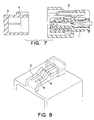
- A device of the foregoing type is shown in cross section in Figure 7. First connector 1 is provided with
locking arm 2.Second connector 3 hascorresponding engagement portion 4 located thereon. When first connector 1 andsecond connector 3 are fitted together, lockingarm 2 rides up overengagement portion 4 until it is in contact with the rear face thereof, thus locking the two parts together. The fitting resistance is generated by the front ofengagement portion 4 contacting the distal end oflocking arm 2. When this is overridden, locking is complete. - A similar device is disclosed in EP 0 503 661. There, the engagement portion is located at an elastic arm which is bended when a hood portion having a detent is overriding it. When this overriding is finished locking is complete.
- However, since such structure requires a substantial force to complete the fitting operation, users sometimes press down on the rear of
locking arm 2 to deliberately disengage it so as to facilitate joinder of the connectors. However, since this prevents lockingarm 2 from contactingengagement portion 4, the fitting resistance is either absent or substantially reduced. As a result, there is no consistent feel and it is difficult for the operator to know whether the assembly is complete. - An alternative device is disclosed in Japanese Utility Model Laid-Open Publication 2-95174 and is shown in perspective in Figure 8 hereof. There is provided a pair of spaced apart locking
arms 5. Between them,resistance arm 6 is located. Lockingarms 5 act in the same way as the corresponding locking arm previously described. In this structure,resistance arm 6 is substantially inflexible, thereby providing a consistent feel for the operator. However, the actuating surface ofresistance arm 6 is so located that it is contacted by the engagement portion of the mating connector (not shown) at the same time as lockingarms 5. This creates a very large pressure and makes it difficult for the operator to fit the devices together completely. Moreover, sinceresistance arm 6 is located between lockingarms 5, the latter are displaced outward to provide the necessary space therefor. Thus, the engagement portion of the complementary connector must also be offset outward, thus requiring a different shape thereof. - It is, therefore, an object of the present Invention to provide a device for generating suitable fitting resistance which will give a consistent operating feel, even if the locking arm is unlocked. It is also an object of the present Invention to provide the foregoing without the necessity of changing the shape of the complementary connector.
- The present Invention is directed to male and female locking connectors with a detent on one connector and a locking element on the other. The locking element rides up over the detent during locking movement and drops down on the other side, thereby bearing against the rear face of the detent and locking the two connectors together. To release, the locking element is disengaged from the detent, usually by pressing on the proximal end thereof.
- There is also provided at least one resistance surface on one of the connectors and a corresponding resistance element, independent of the locking element, on the other connector. The resistant element bears against the resistance surface to generate the desired resistance to movement of the two connectors into their locking position. The resistance element has a leading end facing the leading edge of the resistance surface. They are advantageously located so that the leading edge and leading end contact each other during the fitting movement of the connectors before the locking element contacts the detent. Thus, the initial resistance is created and preferably released before the locking element reaches the detent. Thus, by pressing the two parts together, momentum is built up which will carry the locking element over the detent and into its proper locked position. The leading edge of the resistance surface may be slanted to allow the resistance element to ride thereover without damage to any of the components of the connectors.
- In a preferred form of the device, the leading edge is substantially transverse to the direction of fitting movement and the resistance element has a protuberance adjacent the distal end thereof. This protuberance extends in a transverse direction toward the resistance surface. Therefore, the leading edge contacts the resistance element at a point on the protuberance which is eccentric to the axis of the resistance element. As a result, pressure in the fitting direction causes the resistance element to bend and thereby slide over the leading edge.
- Advantageously, there is provided a pair of resistance elements in the form of upstanding generally planar ribs which are transversely spaced apart. The resistance element is a pair of elongated resistance arms transversely flexible and biased toward the ribs. In this embodiment, the detent is located between the ribs and the locking arm is located between the resistance arms.
- In the accompanying drawings, constituting a part hereof, and in which like reference characters indicate like parts,
- Figure 1
- is a plan view, partly in section, of the male and female connectors according to the Invention before being fitted together;
- Figure 2
- is an elevation in section of connectors similar to those of Figure 1 except for the shape of the engagement surface;
- Figure 3
- is a plan view, similar to that of Figure 1, with the connectors in the partially fitted position of a different embodiment having different shape of the contact surface;
- Figure 4
- is a plan view, similar to that of Figure 3, showing the connectors fully locked;
- Figure 5
- is a plan view, partly in section, of a modification of the Invention;
- Figure 6
- is a sectional elevation of Figure 4;
- Figure 7
- is a view similar that of Figure 2 of a prior art device; and
- Figure 8
- is a perspective view of another prior art device.
- As shown in Figures 1 to 6,
female connector 20 is adapted to receivefitting portion 12 onhousing 10 ofmating connector 11. On the surface thereof,connector 11 is provided withdetent 14 withguide surface 15 andengagement surface 16.Male terminal 13 is located withinfitting portion 12. -
Female connector 20 compriseshousing 21 andhood 23.Female terminal 22 is located within the housing. Lockingarm 25 is provided on one surface thereof and is complementary todetent 14. On either side of lockingarm 25 areresistance arms 29. Each arm carriesprojection 30 which is provided withcontact surface 31 and guidesurface 32.Arms 29 are flexible in a direction transverse to the insertion direction andactive space 24 is located betweenside walls 28 andresistance arms 29 for this purpose. - In one form of the Invention,
engagement surface 16 is slanted, as shown in Figure 1, to facilitate disengagement of the connectors. Alternatively, as shown in Figure 2,engagement surface 16 can be vertical. In this case, the connectors are disengaged by pressing onpressing portion 27 which causesengagement projection 26 to move upwardly (as shown in Figure 2) so that it is no longer in contact withengagement surface 16. Another variation is shown in Figure 5. There,resistance arms 29 extend from the front ofconnector 20 toward the rear thereof. - To assemble the device,
fitting portion 12 ofconnector 11 is inserted intohood 23. Partial insertion of still another embodiment is shown in Figure 3. As can be seen there, contact surfaces 31 are in contact with the leading edges ofribs 17. Further pressure is then exerted which causesresistance arms 29 to bend inwardly, thereby slanting contact surfaces 31. This causesresistance arms 29 to spread and ride up over the outside ofribs 17. - Because of the initial force required to spread
resistance arms 29, considerable momentum is developed betweenconnectors arm 25 rides overengagement surface 16 into the position shown in Figures 4 and 5. As a result, the rear face ofengagement projection 26 bears againstengagement surface 16, thereby locking the connectors together securely. If they are to be disengaged, pressure is exerted on pressingportion 27, causingengagement projection 26 to move upwardly (as shown in Figure 5) so that the connectors can easily be separated. - The provision of locking
arm 25 centrally of the transverse dimension ofconnector 20, coupled with the pair ofresistance arms 29 spaced symmetrically on either side, permits the fitting resistance fromresistance arms 29 to act uniformly on both sides of the device. Thus, no tilting of the connectors will occur. Also, the use of tworesistance arms 29 doubles the fitting resistance obtained. Since the size and/or shape offemale connector 20 is unchanged by the present device, it is capable of use with existing male connectors without any requirement for modification thereof. - Furthermore, if additional fitting resistance is required, it is possible to accomplish this by increasing the width of
resistance arms 29 in the transverse direction. Since the increased dimension is parallel to the upper surface offemale housing 21, no increase in height thereof is necessary. The provision ofsubstantial space 24 eliminates the necessity to increase the lateral width ofhousing 21. Thus, the present Invention is capable of providing substantially increased fitting resistance as desired, without any need to modify either the height or the width thereof, thereby eliminating the need to redesign existing male connectors. - Certain embodiments of the present Invention have been expressly disclosed. However, it is not limited thereto and various modifications thereof will readily suggest themselves to persons of ordinary skill. For example, a single resistance arm on one side of the locking arm can be used in place of the pair shown in the Figures; this would entail the need for only a single upstanding rib on the connector. Moreover, the resistance arms can flex inwardly (toward the locking arm) rather than outwardly as shown. The locking arm and resistance arms have been described as being located on the female connector, while the detent and ribs are on the male connector. However, within the scope of the Invention, one or both of the elements on the female connector can be located on the male connector, and vice versa. In the accompanying Figures, the resistance arms flex in a direction parallel to the upper surface of the connector. Alternatively, flexure can take place perpendicularly to the upper surface with substantially the same effect. In that case,
spaces 24 would be located between the upper surface and the resistance arms. - Although only a limited number of specific embodiments of the present Invention have been expressly disclosed, it is, nonetheless, to be broadly construed, and not to be limited except by the SCOPE of the claims appended hereto.
Claims (7)
- A connector comprising a male connector (11) and female connector (20) comprising a hood (23),characterized in thata detent (14) on one of said male connector (11) and said female connector (20), a locking element (25) on another of said male connector (11) and said female connector (20), said locking element (25) engaging said detent (14) when said male connector (11) and said female connector (20) are in a locked position relative to each other,a resistance surface (17) on one of said male connector (11) and said female connector (20), a resistance element (29) on another of said male connector (11) and said female connector (20), said resistance element (29) being adapted to bear against said resistance surface (17), thereby to generate resistance to a movement of said female connector (20) and said male connector (11) into said locked position,said resistence element (29) having a leading end (30) facing a leading edge of said resistance surface (17), said leading edge and said leading end (30), when in contact with each other, provide in greater resistance to said movement than when said resistance element (29) is in contact with said resistance surface (17), and said leading edge and said leading end (30) are no longer in contact with each other,said male connector (11) has a male terminal (13) and said female connector (20) has a female terminal (22) adapted to mate with said male terminal (13) when said male connector (11) and said female connector (20) are in said locked position,said resistence element (29) is independent of said locking element (25),said leading end (30) and said leading edge being in contact of each other during said movement before said locking element (25) contacts said detent (14), andsaid resistence element (29) and said locking element (25) being flexible in directions substantially transverse to each other.
- The connector of Claim 1 wherein said resistance surface is a generally planar upstanding rib extending substantially parallel to said movement, said resistance element is a resistance arm (29) having a longitudinal axis, flexible in a transverse direction to said movement, and biased toward said rib.
- The connector of Claim 2 wherein said resistance arm has a projection (30) adjacent said leading end extending in said transverse direction toward said rib, a contact surface (31) on said projection adapted to contact said leading edge at a point eccentric to said axis, whereby said movement causes said resistance arm to bend and said projection to be released from contact with said leading edge.
- The connector of Claim 2 wherein said leading edge is substantially perpendicular to said movement.
- The connector of Claim 2 wherein there are two generally planar upstanding ribs (17) spaced apart from each other in said transverse direction and extending substantially parallel to said movement, and
two resistance arms having longitudinal axes (29), flexible in said transverse direction, and each biased toward one of said ribs. - The connector of Claim 5 wherein said detent is between said ribs and said locking arm is between said resistance arms.
- The connector of one of claims 1 to 6, wherein said leading edge and said leading end cease to be in contact with each other during said movement and said greater resistance is released, before said male connector and said female connector have fully reached said locked position.
Applications Claiming Priority (3)
| Application Number | Priority Date | Filing Date | Title |
|---|---|---|---|
| JP108290/96 | 1996-04-26 | ||
| JP10829096A JP3301522B2 (en) | 1996-04-26 | 1996-04-26 | connector |
| JP10829096 | 1996-04-26 |
Publications (2)
| Publication Number | Publication Date |
|---|---|
| EP0803937A1 EP0803937A1 (en) | 1997-10-29 |
| EP0803937B1 true EP0803937B1 (en) | 2001-06-27 |
Family
ID=14480932
Family Applications (1)
| Application Number | Title | Priority Date | Filing Date |
|---|---|---|---|
| EP97107031A Expired - Lifetime EP0803937B1 (en) | 1996-04-26 | 1997-04-28 | Inertia locking connector |
Country Status (4)
| Country | Link |
|---|---|
| US (1) | US5876232A (en) |
| EP (1) | EP0803937B1 (en) |
| JP (1) | JP3301522B2 (en) |
| DE (1) | DE69705352T2 (en) |
Cited By (1)
| Publication number | Priority date | Publication date | Assignee | Title |
|---|---|---|---|---|
| CN108512012A (en) * | 2017-02-28 | 2018-09-07 | 欧姆龙株式会社 | Terminal board |
Families Citing this family (30)
| Publication number | Priority date | Publication date | Assignee | Title |
|---|---|---|---|---|
| JP3467185B2 (en) * | 1998-04-08 | 2003-11-17 | 矢崎総業株式会社 | Connector locking mechanism |
| DE19828636C2 (en) * | 1998-06-26 | 2000-07-06 | Framatome Connectors Int | Snap-in connector |
| JP3296298B2 (en) * | 1998-07-23 | 2002-06-24 | 住友電装株式会社 | Waterproof connector |
| JP3651311B2 (en) * | 1999-05-26 | 2005-05-25 | ソニー株式会社 | Optical connector |
| US6364686B2 (en) * | 1999-11-30 | 2002-04-02 | Tyco Electronics Amp Gmbh | Electrical and/or optical connector with a latching arm |
| JP3648432B2 (en) | 2000-05-25 | 2005-05-18 | 矢崎総業株式会社 | Inertia lock connector |
| JP3840039B2 (en) | 2000-06-01 | 2006-11-01 | 矢崎総業株式会社 | Inertia lock connector |
| JP3470888B2 (en) * | 2000-06-21 | 2003-11-25 | タイコエレクトロニクスアンプ株式会社 | Connector assembly |
| JP2002184522A (en) * | 2000-12-12 | 2002-06-28 | Jst Mfg Co Ltd | Connector assembly with lock mechanism |
| JP3826799B2 (en) * | 2001-03-02 | 2006-09-27 | 住友電装株式会社 | connector |
| US6565383B1 (en) * | 2002-09-11 | 2003-05-20 | Hon Hai Precision Ind. Co., Ltd. | Electrical connector with locking member |
| US6585536B1 (en) * | 2002-09-11 | 2003-07-01 | Hon Hai Precision Ind. Co., Ltd. | Cable end connector with locking member |
| US6585537B1 (en) * | 2002-10-24 | 2003-07-01 | Hon Hai Precision Ind. Co., Ltd. | Cable end connector with locking member |
| US8109883B2 (en) | 2006-09-28 | 2012-02-07 | Tyco Healthcare Group Lp | Cable monitoring apparatus |
| US8668651B2 (en) | 2006-12-05 | 2014-03-11 | Covidien Lp | ECG lead set and ECG adapter system |
| JP2008270127A (en) * | 2007-04-25 | 2008-11-06 | Sumitomo Wiring Syst Ltd | Connector |
| US8038484B2 (en) | 2007-12-11 | 2011-10-18 | Tyco Healthcare Group Lp | ECG electrode connector |
| USD737979S1 (en) | 2008-12-09 | 2015-09-01 | Covidien Lp | ECG electrode connector |
| US8694080B2 (en) * | 2009-10-21 | 2014-04-08 | Covidien Lp | ECG lead system |
| CA2746944C (en) | 2010-07-29 | 2018-09-25 | Tyco Healthcare Group Lp | Ecg adapter system and method |
| JP5674124B2 (en) * | 2010-12-21 | 2015-02-25 | 矢崎総業株式会社 | Connector housing |
| CN103687537B (en) | 2011-07-22 | 2016-02-24 | 柯惠有限合伙公司 | Ecg electrode connector |
| US8634901B2 (en) | 2011-09-30 | 2014-01-21 | Covidien Lp | ECG leadwire system with noise suppression and related methods |
| US9408546B2 (en) | 2013-03-15 | 2016-08-09 | Covidien Lp | Radiolucent ECG electrode system |
| EP2967396B1 (en) | 2013-03-15 | 2019-02-13 | Kpr U.S., Llc | Electrode connector with a conductive member |
| USD771818S1 (en) | 2013-03-15 | 2016-11-15 | Covidien Lp | ECG electrode connector |
| JP2014220146A (en) * | 2013-05-09 | 2014-11-20 | 住友電装株式会社 | Connector |
| EP3252876B1 (en) * | 2016-06-01 | 2019-05-01 | Aptiv Technologies Limited | Electrical connector with encoding function |
| JP6801516B2 (en) * | 2017-02-28 | 2020-12-16 | オムロン株式会社 | Terminal block |
| DE102017123390B4 (en) * | 2017-10-09 | 2019-09-05 | Te Connectivity Germany Gmbh | Contact device and contact system |
Citations (1)
| Publication number | Priority date | Publication date | Assignee | Title |
|---|---|---|---|---|
| EP0757411A2 (en) * | 1995-08-03 | 1997-02-05 | Sumitomo Wiring Systems, Ltd. | Connector |
Family Cites Families (10)
| Publication number | Priority date | Publication date | Assignee | Title |
|---|---|---|---|---|
| DE2942327A1 (en) * | 1979-10-19 | 1981-05-14 | Hoechst Ag, 6000 Frankfurt | METHOD FOR PRODUCING COPOLYMERISATES CONTAINING OH GROUPS |
| JPH0433666Y2 (en) * | 1988-05-13 | 1992-08-12 | ||
| JPH0295174A (en) * | 1988-09-27 | 1990-04-05 | Shinko Electric Co Ltd | Power conversion device |
| US5004431A (en) * | 1989-02-06 | 1991-04-02 | Molex Incorporated | Reinforced connector latch |
| JPH0770340B2 (en) * | 1990-03-27 | 1995-07-31 | 矢崎総業株式会社 | Connector coupling detector |
| JP2571310B2 (en) * | 1990-12-14 | 1997-01-16 | 矢崎総業株式会社 | Connector lock security mechanism |
| JPH04220972A (en) * | 1990-12-21 | 1992-08-11 | Kansei Corp | Locking device for electric connector |
| JP2522319Y2 (en) * | 1991-03-13 | 1997-01-16 | 矢崎総業株式会社 | connector |
| US5403199A (en) * | 1993-10-21 | 1995-04-04 | Electrical Mechanical Products Inc. | Low insertion force high current terminal |
| JP2597042Y2 (en) * | 1993-12-21 | 1999-06-28 | 住友電装株式会社 | connector |
-
1996
- 1996-04-26 JP JP10829096A patent/JP3301522B2/en not_active Expired - Lifetime
-
1997
- 1997-04-23 US US08/842,478 patent/US5876232A/en not_active Expired - Lifetime
- 1997-04-28 EP EP97107031A patent/EP0803937B1/en not_active Expired - Lifetime
- 1997-04-28 DE DE69705352T patent/DE69705352T2/en not_active Expired - Lifetime
Patent Citations (1)
| Publication number | Priority date | Publication date | Assignee | Title |
|---|---|---|---|---|
| EP0757411A2 (en) * | 1995-08-03 | 1997-02-05 | Sumitomo Wiring Systems, Ltd. | Connector |
Cited By (2)
| Publication number | Priority date | Publication date | Assignee | Title |
|---|---|---|---|---|
| CN108512012A (en) * | 2017-02-28 | 2018-09-07 | 欧姆龙株式会社 | Terminal board |
| CN108512012B (en) * | 2017-02-28 | 2019-09-20 | 欧姆龙株式会社 | Terminal board |
Also Published As
| Publication number | Publication date |
|---|---|
| US5876232A (en) | 1999-03-02 |
| DE69705352D1 (en) | 2001-08-02 |
| JPH09293566A (en) | 1997-11-11 |
| DE69705352T2 (en) | 2002-05-02 |
| JP3301522B2 (en) | 2002-07-15 |
| EP0803937A1 (en) | 1997-10-29 |
Similar Documents
| Publication | Publication Date | Title |
|---|---|---|
| EP0803937B1 (en) | Inertia locking connector | |
| JP2838137B2 (en) | Female electrical terminal | |
| KR100673281B1 (en) | Structure for interlocking connectors | |
| US6712636B2 (en) | Connector lock mechanism | |
| JPH03116672A (en) | Electric connector | |
| EP1889335B1 (en) | Electrical connector having improved releasable locking means | |
| US5484223A (en) | Double terminal stop connector | |
| US6203385B1 (en) | Electrical contact | |
| JP2907373B2 (en) | Connector lock connection detection structure | |
| EP0606967B1 (en) | Connector | |
| EP1107380A1 (en) | Connector | |
| JPH0778651A (en) | Electric connector assembly | |
| US6012946A (en) | Connector fitting-detection mechanism | |
| JP3218155B2 (en) | Connector with cam member | |
| JP2911020B2 (en) | Electrical connection terminal | |
| EP1137117A2 (en) | An electrical connector plug | |
| JP3390331B2 (en) | Female terminal fitting | |
| JPH08115766A (en) | Connector | |
| JP3127825B2 (en) | connector | |
| JPH0517823Y2 (en) | ||
| JP2736473B2 (en) | Latch for electrical connector housing | |
| JP3541748B2 (en) | Terminal relay structure | |
| JP4242378B2 (en) | Electrical connector with locking mechanism | |
| JPH0654255U (en) | Connector with cam member | |
| JPS6213333Y2 (en) |
Legal Events
| Date | Code | Title | Description |
|---|---|---|---|
| PUAI | Public reference made under article 153(3) epc to a published international application that has entered the european phase |
Free format text: ORIGINAL CODE: 0009012 |
|
| 17P | Request for examination filed |
Effective date: 19970428 |
|
| AK | Designated contracting states |
Kind code of ref document: A1 Designated state(s): DE FR GB |
|
| 17Q | First examination report despatched |
Effective date: 19981103 |
|
| GRAG | Despatch of communication of intention to grant |
Free format text: ORIGINAL CODE: EPIDOS AGRA |
|
| GRAG | Despatch of communication of intention to grant |
Free format text: ORIGINAL CODE: EPIDOS AGRA |
|
| GRAH | Despatch of communication of intention to grant a patent |
Free format text: ORIGINAL CODE: EPIDOS IGRA |
|
| GRAH | Despatch of communication of intention to grant a patent |
Free format text: ORIGINAL CODE: EPIDOS IGRA |
|
| GRAA | (expected) grant |
Free format text: ORIGINAL CODE: 0009210 |
|
| AK | Designated contracting states |
Kind code of ref document: B1 Designated state(s): DE FR GB |
|
| REF | Corresponds to: |
Ref document number: 69705352 Country of ref document: DE Date of ref document: 20010802 |
|
| ET | Fr: translation filed | ||
| REG | Reference to a national code |
Ref country code: GB Ref legal event code: IF02 |
|
| PLBE | No opposition filed within time limit |
Free format text: ORIGINAL CODE: 0009261 |
|
| STAA | Information on the status of an ep patent application or granted ep patent |
Free format text: STATUS: NO OPPOSITION FILED WITHIN TIME LIMIT |
|
| 26N | No opposition filed | ||
| PGFP | Annual fee paid to national office [announced via postgrant information from national office to epo] |
Ref country code: GB Payment date: 20070425 Year of fee payment: 11 |
|
| GBPC | Gb: european patent ceased through non-payment of renewal fee |
Effective date: 20080428 |
|
| PG25 | Lapsed in a contracting state [announced via postgrant information from national office to epo] |
Ref country code: GB Free format text: LAPSE BECAUSE OF NON-PAYMENT OF DUE FEES Effective date: 20080428 |
|
| REG | Reference to a national code |
Ref country code: FR Ref legal event code: PLFP Year of fee payment: 20 |
|
| PGFP | Annual fee paid to national office [announced via postgrant information from national office to epo] |
Ref country code: FR Payment date: 20160309 Year of fee payment: 20 |
|
| PGFP | Annual fee paid to national office [announced via postgrant information from national office to epo] |
Ref country code: DE Payment date: 20160419 Year of fee payment: 20 |
|
| REG | Reference to a national code |
Ref country code: DE Ref legal event code: R071 Ref document number: 69705352 Country of ref document: DE |