EP0803393A2 - Fuel tank inlet cover for motor vehicle - Google Patents
Fuel tank inlet cover for motor vehicle Download PDFInfo
- Publication number
- EP0803393A2 EP0803393A2 EP97104037A EP97104037A EP0803393A2 EP 0803393 A2 EP0803393 A2 EP 0803393A2 EP 97104037 A EP97104037 A EP 97104037A EP 97104037 A EP97104037 A EP 97104037A EP 0803393 A2 EP0803393 A2 EP 0803393A2
- Authority
- EP
- European Patent Office
- Prior art keywords
- fuel filler
- flap
- bolt
- filler flap
- tank
- Prior art date
- Legal status (The legal status is an assumption and is not a legal conclusion. Google has not performed a legal analysis and makes no representation as to the accuracy of the status listed.)
- Withdrawn
Links
Images

Classifications
-
- E—FIXED CONSTRUCTIONS
- E05—LOCKS; KEYS; WINDOW OR DOOR FITTINGS; SAFES
- E05B—LOCKS; ACCESSORIES THEREFOR; HANDCUFFS
- E05B83/00—Vehicle locks specially adapted for particular types of wing or vehicle
- E05B83/28—Locks for glove compartments, console boxes, fuel inlet covers or the like
- E05B83/34—Locks for glove compartments, console boxes, fuel inlet covers or the like for fuel inlet covers essentially flush with the vehicle surface
-
- B—PERFORMING OPERATIONS; TRANSPORTING
- B60—VEHICLES IN GENERAL
- B60K—ARRANGEMENT OR MOUNTING OF PROPULSION UNITS OR OF TRANSMISSIONS IN VEHICLES; ARRANGEMENT OR MOUNTING OF PLURAL DIVERSE PRIME-MOVERS IN VEHICLES; AUXILIARY DRIVES FOR VEHICLES; INSTRUMENTATION OR DASHBOARDS FOR VEHICLES; ARRANGEMENTS IN CONNECTION WITH COOLING, AIR INTAKE, GAS EXHAUST OR FUEL SUPPLY OF PROPULSION UNITS IN VEHICLES
- B60K15/00—Arrangement in connection with fuel supply of combustion engines or other fuel consuming energy converters, e.g. fuel cells; Mounting or construction of fuel tanks
- B60K15/03—Fuel tanks
- B60K15/04—Tank inlets
- B60K15/05—Inlet covers
-
- E—FIXED CONSTRUCTIONS
- E05—LOCKS; KEYS; WINDOW OR DOOR FITTINGS; SAFES
- E05B—LOCKS; ACCESSORIES THEREFOR; HANDCUFFS
- E05B17/00—Accessories in connection with locks
- E05B17/0025—Devices for forcing the wing firmly against its seat or to initiate the opening of the wing
- E05B17/0033—Devices for forcing the wing firmly against its seat or to initiate the opening of the wing for opening only
- E05B17/0037—Spring-operated
-
- B—PERFORMING OPERATIONS; TRANSPORTING
- B60—VEHICLES IN GENERAL
- B60K—ARRANGEMENT OR MOUNTING OF PROPULSION UNITS OR OF TRANSMISSIONS IN VEHICLES; ARRANGEMENT OR MOUNTING OF PLURAL DIVERSE PRIME-MOVERS IN VEHICLES; AUXILIARY DRIVES FOR VEHICLES; INSTRUMENTATION OR DASHBOARDS FOR VEHICLES; ARRANGEMENTS IN CONNECTION WITH COOLING, AIR INTAKE, GAS EXHAUST OR FUEL SUPPLY OF PROPULSION UNITS IN VEHICLES
- B60K15/00—Arrangement in connection with fuel supply of combustion engines or other fuel consuming energy converters, e.g. fuel cells; Mounting or construction of fuel tanks
- B60K15/03—Fuel tanks
- B60K15/04—Tank inlets
- B60K15/05—Inlet covers
- B60K2015/0515—Arrangements for closing or opening of inlet cover
- B60K2015/053—Arrangements for closing or opening of inlet cover with hinged connection to the vehicle body
-
- B—PERFORMING OPERATIONS; TRANSPORTING
- B60—VEHICLES IN GENERAL
- B60K—ARRANGEMENT OR MOUNTING OF PROPULSION UNITS OR OF TRANSMISSIONS IN VEHICLES; ARRANGEMENT OR MOUNTING OF PLURAL DIVERSE PRIME-MOVERS IN VEHICLES; AUXILIARY DRIVES FOR VEHICLES; INSTRUMENTATION OR DASHBOARDS FOR VEHICLES; ARRANGEMENTS IN CONNECTION WITH COOLING, AIR INTAKE, GAS EXHAUST OR FUEL SUPPLY OF PROPULSION UNITS IN VEHICLES
- B60K15/00—Arrangement in connection with fuel supply of combustion engines or other fuel consuming energy converters, e.g. fuel cells; Mounting or construction of fuel tanks
- B60K15/03—Fuel tanks
- B60K15/04—Tank inlets
- B60K15/05—Inlet covers
- B60K2015/0561—Locking means for the inlet cover
Definitions
- the invention relates to a fuel filler flap for motor vehicles used to cover the fuel filler neck, the fuel filler flap being closed by a counter to a restoring force e.g. is held by means of a Bowden cable longitudinally displaceable bolt, which in the retracted state releases a closure element of the tank flap for opening the tank flap.
- the object of the invention is to design the tank flaps mentioned at the outset in such a way that the tank flap is actuated when the remote-controlled bolt is actuated automatically reaches such an open position that the edge of the fuel filler flap can easily be gripped by the user with his finger in order to be able to complete the opening movement.
- an opening spring is assigned to the fuel filler flap and, in addition, the bolt is assigned a run-up slope which strikes the closure element when the bolt returns to the closed position and thereby opens the fuel filler flap to such an extent that the flap edge is separated from the user by the Fingers can be caught.
- the remote-controlled bolt mentioned has two functions. Once it serves as a locking bolt. It therefore locks the fuel filler flap in the closed state. On the other hand, its retrograde movement, i.e. its movement from the retracted position back to the closed position, is used to open the fuel filler flap to a small extent, and - as mentioned - to such an extent that the flap edge can be gripped. It goes without saying that under these conditions, recessed grips become unnecessary and the outer skin of the vehicle and the fuel filler flap can be made smooth on the outside.
- the outer skin 1 of the vehicle has an opening 2 through which a nozzle (not shown) for filling the fuel tank is accessible.
- This opening 2 is covered by a fuel filler flap 3, which is pivotably arranged on the vehicle by means of an arm 4 on an axle 5.
- 1, the edge 6 of the tank flap 3 overlaps the stepped edges 7 which delimit the opening 2. Seals can be provided in the gap in the area of the overlap.
- a bracket 8 mounted on the vehicle for a longitudinally displaceable bolt 9, which assumes the closed position in the advanced position according to FIG. 1, but for the remote control of the lid closure by means of a Bowden cable against a spring, not shown, a retractive movement in the direction of Arrow 10 can run. If the Bowden cable is actuated for the purpose of opening the tank flap 3, the bolt 9 moves in the direction of the arrow 10. If the Bowden cable is relieved, the bolt 9 tries to return to the original position according to FIG. 1.
- a closure element 11 in the form of a component projecting at the bottom in the direction of the holder 8 (the projection is designated by 12).
- this projection 12 underpins the front end of the bolt 9.
- an S-shaped leaf spring 13 is also provided, which is supported on the fuel filler flap 3 at the top and on the holder 8 at the bottom and when the fuel filler flap is closed 3 is excited.
- the bolt 9 executes a retracting movement.
- the projection 12 no longer finds an abutment in the bolt 9, and under the action of the leaf spring 13 the fuel filler flap 3 then comes into the position according to FIG. 2.
- the spring 13 is understandably tensioned when the fuel filler flap 3 is closed and, if necessary, can also be replaced by another spring. However, it should be secured against falling off with the upper leg 13 ′ by insertion into a pocket 14 located on the tank flap 3. However, it is important in any case that the spring is tensioned when the fuel filler flap 3 is closed, so that it can bring about the described effect (formation of an enlarged gap) later when the fuel filler flap 3 is opened.
- the type of closure according to the invention has the great advantage that neither 6 bulges nor 7 bulges are required at the edge.
Landscapes
- Engineering & Computer Science (AREA)
- Life Sciences & Earth Sciences (AREA)
- Sustainable Development (AREA)
- Sustainable Energy (AREA)
- Chemical & Material Sciences (AREA)
- Combustion & Propulsion (AREA)
- Transportation (AREA)
- Mechanical Engineering (AREA)
- Cooling, Air Intake And Gas Exhaust, And Fuel Tank Arrangements In Propulsion Units (AREA)
Abstract
Die Erfindung geht aus von einer Tankklappe (3), die im geschlossenen Zustand durch einen unter Federspannung stehenden Bolzen (9) gehalten ist, der im zurückgezogenen Zustand ein Verschlusselement (11) der Tankklappe zu deren Öffnung freigibt. Um Griffmulden an der Aussenhaut des Fahrzeuges (1) bzw. der Tankklappe überflüssig zu machen, ist der Tankklappe erfindungsgemäss eine Öffnungsfeder (13) zugeordnet und zudem ist dem Bolzen eine Auflaufschräge (14) in der Weise zugeordnet, dass diese beim Zurückkehren des Bolzens in seine Schliesstellung auf ein Verschlusselement (11,12) der Tankklappe auftrifft und die Tankklappe derart weit aufklappt, dass der Rand (6) der Tankklappe ohne weiteres mit einem Finger erfasst werden kann.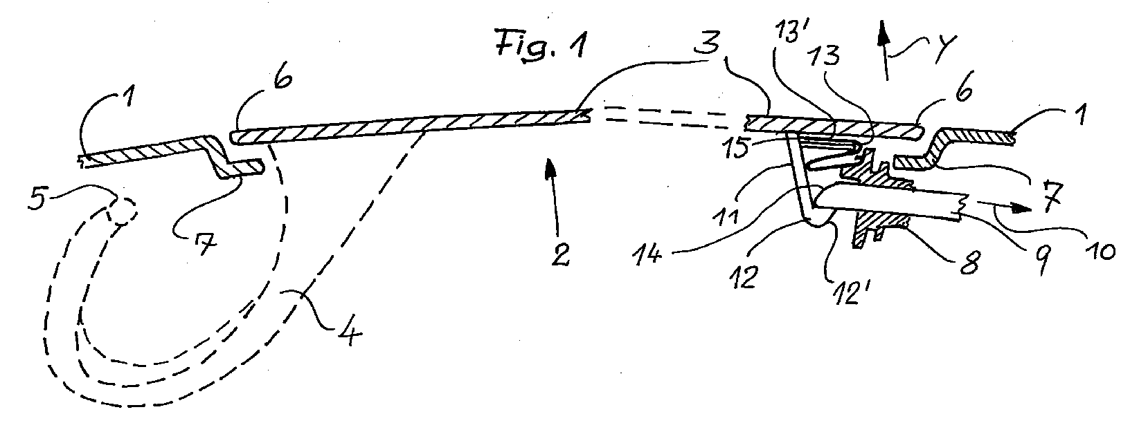
Description
Die Erfindung betrifft eine zum Überdecken des Kraftstoffeinfüllstutzens dienende Tankklappe für Kraftfahrzeuge, wobei die Tankklappe im geschlossenen Zustand von einem gegen eine Rückstellkraft z.B. mittels Bowdenzug längsverschiebbaren Bolzen gehalten ist, der im zurückgesogenen Zustand ein Verschlusselement der Tankklappe zum Öffnen der Tankklappe freigibt.The invention relates to a fuel filler flap for motor vehicles used to cover the fuel filler neck, the fuel filler flap being closed by a counter to a restoring force e.g. is held by means of a Bowden cable longitudinally displaceable bolt, which in the retracted state releases a closure element of the tank flap for opening the tank flap.
Bei den bekannten Tankklappen dieser Art müssen an der Aussenhaut des Fahrzeuges und/oder an der Tankklappe selbst kleine Griffmulden vorgesehen sein, um die Tankklappe nach Betätigen des vorerwähnten Bolzens manuell öffnen zu können.In the known fuel filler flaps of this type, small recessed grips must be provided on the outer skin of the vehicle and / or on the fuel filler flap in order to be able to open the fuel filler flap manually after actuating the aforementioned bolt.
Der Erfindunq liegt die Aufgabe zugrunde, die eingangs erwähnten Tankklappen so auszubilden, dass mit der Betätigung des fernbedienbaren Bolzens die Tankklappe selbsttätig in eine solche Offenstellung gelangt, dass der Rand der Tankklappe ohne weiteres vom Benutzer mit dem Finger unterfasst werden kann, um so die Öffnungsbewegung vollenden zu können.The object of the invention is to design the tank flaps mentioned at the outset in such a way that the tank flap is actuated when the remote-controlled bolt is actuated automatically reaches such an open position that the edge of the fuel filler flap can easily be gripped by the user with his finger in order to be able to complete the opening movement.
Zur Lösung dieser Aufgabe ist erfindungsgemäss der Tankklappe eine Öffnungsfeder zugeordnet und zudem ist dem Bolzen eine Auflaufschräge zugeordnet, die beim Zurückkehren des Bolzens in die Schliesstellung auf das Verschlusselement auftrifft und dabei die Tankklappe in einem solchen Masse weiter aufklappt, dass der Klappenrand vom Benutzer mit dem Finger unterfasst werden kann.To solve this problem, according to the invention an opening spring is assigned to the fuel filler flap and, in addition, the bolt is assigned a run-up slope which strikes the closure element when the bolt returns to the closed position and thereby opens the fuel filler flap to such an extent that the flap edge is separated from the user by the Fingers can be caught.
Demgemäss hat der erwähnte fernbedienbare Bolzen zwei Aufgaben. Einmal dient er als Schliessbolzen. Er arretiert also die Tankklappe im geschlossenen Zustand. Zum anderen wird seine rückläufige Bewegung, also seine Bewegung von der zurückgezogenen Stellung zurück in die Schliesstellung dazu genutzt, um die Tankklappe um ein geringes Mass weiter zu öffnen, und zwar - wie erwähnt - um ein solches Mass, dass der Klappenrand unterfasst werden kann. Es versteht sich, dass unter diesen Voraussetzungen Griffmulden überflüssig werden und die Aussenhaut des Fahrzeuges und die Tankklappe aussen glatt ausgeführt werden können.Accordingly, the remote-controlled bolt mentioned has two functions. Once it serves as a locking bolt. It therefore locks the fuel filler flap in the closed state. On the other hand, its retrograde movement, i.e. its movement from the retracted position back to the closed position, is used to open the fuel filler flap to a small extent, and - as mentioned - to such an extent that the flap edge can be gripped. It goes without saying that under these conditions, recessed grips become unnecessary and the outer skin of the vehicle and the fuel filler flap can be made smooth on the outside.
Weitere Einzelheiten der Erfindung werden anhand der Zeichnung erläutert, in der ein Ausführungsbeispiel der Erfindung dargestellt ist. Es zeigen :
- Fig. 1 einen Teilschnitt durch die Aussenhaut eines Strassenkraftfahrzeuges im Bereich seines Kraftstoffeinfüllstutzens und
- Fig. 2 und 3 je Teilschnitte durch die Tankklappe gemäss Fig. 1 im Bereich der Verschlusselemente, wobei gemäss Fig. 2 die Tankklappe bereits geöffnet und gemäss Fig. 3 die Tankklappe noch weiter aufgeklappt ist.
- Fig. 1 shows a partial section through the outer skin of a road motor vehicle in the area of its fuel filler neck and
- 2 and 3 for each partial section through the tank flap according to FIG. 1 in the area of the closure elements, wherein according to FIG. 2 the tank flap is already open and according to FIG. 3 the tank flap is opened further.
Die Aussenhaut 1 des Fahrzeuges hat eine Durchbrechung 2, über die ein nicht dargestellter Stutzen zum Befüllen des Brennstofftanks zugänglich ist. Diese Durchbrechung 2 wird von einer Tankklappe 3 überdeckt, die am Fahrzeug mittels eines Armes 4 an einer Achse 5 verschwenkbar angeordnet ist. Im geschlossenen Zustand der Tankklappe 3 gemäss Fig. 1 überlappt der Rand 6 der Tankklappe 3 die gestuften Ränder 7, die die Durchbrechung 2 begrenzen. Im Spalt im Bereich der Überlappung können Dichtungen vorgesehen sein.The
Nahe unterhalb eines Abschnitts des Randes befindet sich eine am Fahrzeug gelagerte Halterung 8 für einen längsverschiebbbaren Bolzen 9, der in vorgeschobener Stellung gemäss Fig. 1 die Schliesstellung einnimmt, jedoch zur Fernbedienung des Deckelverschlusses mittels Bowdenzug gegen eine nicht dargestellte Feder eine rückziehende Bewegung in Richtung des Pfeiles 10 ausführen kann. Wird der Bowdenzug zum Zwecke der Öffnung der Tankklapee 3 betätigt, so bewegt sich der Bolzen 9 in Richtung des Pfeiles 10. Wird der Bowdenzug entlastet, so versucht der Bolzen 9 in die ursprüngliche Stellung gemäss Fig. 1 zu gelangen.Close below a section of the edge is a
Am Rand 6 befindet sich ein Verschlusselement 11 in Form eines unten in Richtung auf die Halterung 8 vorspringenden Bauteiles ( der Vorsprung ist mit 12 bezeichnet ). Bei geschlossener Tankklappe 3 gemäss Fig. 1 unterfasst dieser Vorsprung 12 das vordere Ende des Bolzens 9. Ferner ist noch eine s-förmige Blattfeder 13 vorgesehen, die sich oben an der Tankklappe 3 und unten an der Halterung 8 abstützt und im geschlossenen Zustand der Tankklappe 3 gespannt ist.At the
Zum Öffnen der Tankklappe 3 führt der Bolzen 9 eine rückziehende Bewegung aus. Der Vorsprung 12 findet in dem Bolzen 9 kein Widerlager mehr, und unter der Wirkung der Blattfeder 13 gelangt dann die Tankklappe 3 in die Stellung gemäss Fig. 2. Der mittlerweise in seine Ursprungslage zurückkehrende Bolzen 9 trifft dann mit seiner vorne gelegenen schräg nach hinten oben gerichteten Auflauffläche 14 auf den Vorsprung 12 der durch die Blattfeder 13 oben gehaltenen Tankklappe 3, wobei eine weitere Verschwenkung der Tankklappe 3 entsteht und sich nunmehr zwischen den Rändern 6 und 7 ein solcher Spalt bei x ergibt, dass hier der Benutzer ohne weiteres einen Finger einführen kann, um so die Öffnungsbewegung der Tankklappe 3 im Sinne des Pfeiles y zu vollenden.To open the
Zum Verschliessen der Tankklappe 3 wird diese in die Schliesstellung geklappt, wobei die unten gelegene Schräge 12' des Vorsprunges 12 den Bolzen 9 nach hinten verdrängt. Schliesslich kann der Bolzen 9 wieder einfallen und die Schliesstellung gemäss Fig. 3 einnehmen.To close the
Die Feder 13 wird verständlicherweise beim Zuklappen der Tankklappe 3 gespannt und kann ggfs. auch durch eine andere Feder ersetzt werden. Sie sollte jedoch mit dem oberen Schenkel 13' durch Einführen in eine an der Tankklappe 3 befindliche Tasche 14 gegen Abfallen gesichert sein. Wichtig ist aber in jedem Falle, dass die Feder beim Schliessen der Tankklappe 3 gespannt wird, damit sie später beim Öffnen der Tankklappe 3 die beschriebene Wirkung ( Bildung eines vergrösserten Spaltes ) zustandebringen kann.The
Die erfindungsgemässe Verschlussart hat den grossen Vorteil, dass weder am Rand 6 Auswölbungen noch am Rand 7 Einwölbungen erforderlich sind.The type of closure according to the invention has the great advantage that neither 6 bulges nor 7 bulges are required at the edge.
Claims (6)
Applications Claiming Priority (2)
| Application Number | Priority Date | Filing Date | Title |
|---|---|---|---|
| DE19616315 | 1996-04-24 | ||
| DE1996116315 DE19616315A1 (en) | 1996-04-24 | 1996-04-24 | Fuel filler flap for motor vehicles |
Publications (2)
| Publication Number | Publication Date |
|---|---|
| EP0803393A2 true EP0803393A2 (en) | 1997-10-29 |
| EP0803393A3 EP0803393A3 (en) | 1999-05-19 |
Family
ID=7792275
Family Applications (1)
| Application Number | Title | Priority Date | Filing Date |
|---|---|---|---|
| EP97104037A Withdrawn EP0803393A3 (en) | 1996-04-24 | 1997-03-11 | Fuel tank inlet cover for motor vehicle |
Country Status (2)
| Country | Link |
|---|---|
| EP (1) | EP0803393A3 (en) |
| DE (1) | DE19616315A1 (en) |
Cited By (3)
| Publication number | Priority date | Publication date | Assignee | Title |
|---|---|---|---|---|
| DE19827194A1 (en) * | 1998-06-18 | 1999-12-23 | Volkswagen Ag | New design of fixing mechanism for flap closing fuel insertion area of vehicle |
| DE19920843A1 (en) * | 1999-05-06 | 2000-11-09 | Volkswagen Ag | Tank flap module for a motor vehicle |
| FR2871431A1 (en) | 2004-06-14 | 2005-12-16 | Peugeot Citroen Automobiles Sa | Closure for e.g. tourist car, has spring acting on bent arm having end connected with closing shutter, where spring pivots between three distinct positions such as closed position, half-open position and open position of shutter |
Families Citing this family (5)
| Publication number | Priority date | Publication date | Assignee | Title |
|---|---|---|---|---|
| DE19842690B4 (en) * | 1998-09-17 | 2009-02-12 | Volkswagen Ag | Covering device for an opening, in particular a body opening of a motor vehicle, with a flap |
| DE10148199A1 (en) | 2001-09-21 | 2003-04-10 | Volkswagen Ag | Actuating device for a cover of a body opening |
| DE102007035492B4 (en) | 2007-07-28 | 2017-02-16 | Volkswagen Ag | door assembly |
| DE102007035491A1 (en) | 2007-07-28 | 2009-01-29 | GM Global Technology Operations, Inc., Detroit | Tank flap unit |
| KR101823899B1 (en) * | 2015-12-24 | 2018-01-31 | 현대자동차주식회사 | Structure of opening and closing fuel door |
Family Cites Families (1)
| Publication number | Priority date | Publication date | Assignee | Title |
|---|---|---|---|---|
| JPS58126227U (en) * | 1982-02-19 | 1983-08-27 | 株式会社ニフコ | Fuel inlet cover plate opening/closing device |
-
1996
- 1996-04-24 DE DE1996116315 patent/DE19616315A1/en not_active Withdrawn
-
1997
- 1997-03-11 EP EP97104037A patent/EP0803393A3/en not_active Withdrawn
Cited By (6)
| Publication number | Priority date | Publication date | Assignee | Title |
|---|---|---|---|---|
| DE19827194A1 (en) * | 1998-06-18 | 1999-12-23 | Volkswagen Ag | New design of fixing mechanism for flap closing fuel insertion area of vehicle |
| DE19827194B4 (en) * | 1998-06-18 | 2012-06-06 | Volkswagen Ag | Closure flap for a tank trough of a motor vehicle |
| DE19920843A1 (en) * | 1999-05-06 | 2000-11-09 | Volkswagen Ag | Tank flap module for a motor vehicle |
| EP1050423A3 (en) * | 1999-05-06 | 2001-04-04 | Volkswagen Aktiengesellschaft | Fuel tank inlet cover assembly for motor vehicles |
| FR2871431A1 (en) | 2004-06-14 | 2005-12-16 | Peugeot Citroen Automobiles Sa | Closure for e.g. tourist car, has spring acting on bent arm having end connected with closing shutter, where spring pivots between three distinct positions such as closed position, half-open position and open position of shutter |
| EP1607261A1 (en) | 2004-06-14 | 2005-12-21 | Peugeot Citroen Automobiles S.A. | Obturator for a motor vehicle body, and motor vehicle equipped with such an obturator |
Also Published As
| Publication number | Publication date |
|---|---|
| DE19616315A1 (en) | 1997-10-30 |
| EP0803393A3 (en) | 1999-05-19 |
Similar Documents
| Publication | Publication Date | Title |
|---|---|---|
| DE68902033T2 (en) | ANIMAL TRAP. | |
| DE3247308C2 (en) | Locking mechanism for a cassette provided with a lid | |
| DE10307355B4 (en) | Closing device for a filler pipe of an automotive tank | |
| EP0803393A2 (en) | Fuel tank inlet cover for motor vehicle | |
| DE2644848A1 (en) | VEHICLE ROOF | |
| DE1728535B1 (en) | Electric dry shaver | |
| DE9217849U1 (en) | Locking mechanism for doors or folding walls | |
| DE4004656C1 (en) | ||
| DE3507349A1 (en) | Lock | |
| DE1553467A1 (en) | lock | |
| DE1761041B1 (en) | Form box | |
| DE19843976B4 (en) | Detergent dispenser for a dishwasher | |
| DE19842690B4 (en) | Covering device for an opening, in particular a body opening of a motor vehicle, with a flap | |
| EP2025279A2 (en) | Filter bag with retaining plate | |
| DE3303991C2 (en) | ||
| DE60208947T2 (en) | Lock for a motor vehicle door and arrangement of such a device on a wall of this door | |
| DE3146750A1 (en) | CONTAINER BAG MADE OF FLEXIBLE WALL FILMS WITH SHOULDER OPENING | |
| DE3222232C1 (en) | Garbage collector | |
| DE2759752C2 (en) | Garbage cans | |
| DE2139916C3 (en) | Device for sorting out edge notch cards | |
| DE19708777C2 (en) | Device for facilitating removal of a lint filter from a tumble dryer | |
| DE9205547U1 (en) | Large garbage containers | |
| DE1655725A1 (en) | Vehicle roof that can be opened with wind deflector | |
| DE4036325A1 (en) | Dispenser for paper hankies/or sheets - has housing with base and lid, with removal hole adjustable in size by means of flap | |
| DE2458995C2 (en) | DEVICE FOR CATCHING ANIMALS |
Legal Events
| Date | Code | Title | Description |
|---|---|---|---|
| PUAI | Public reference made under article 153(3) epc to a published international application that has entered the european phase |
Free format text: ORIGINAL CODE: 0009012 |
|
| AK | Designated contracting states |
Kind code of ref document: A2 Designated state(s): AT DE ES FR GB IT NL PT SE |
|
| PUAL | Search report despatched |
Free format text: ORIGINAL CODE: 0009013 |
|
| AK | Designated contracting states |
Kind code of ref document: A3 Designated state(s): AT DE ES FR GB IT NL PT SE |
|
| STAA | Information on the status of an ep patent application or granted ep patent |
Free format text: STATUS: THE APPLICATION IS DEEMED TO BE WITHDRAWN |
|
| 18D | Application deemed to be withdrawn |
Effective date: 19991001 |