EP0803326A2 - Polishing apparatus - Google Patents
Polishing apparatus Download PDFInfo
- Publication number
- EP0803326A2 EP0803326A2 EP97106937A EP97106937A EP0803326A2 EP 0803326 A2 EP0803326 A2 EP 0803326A2 EP 97106937 A EP97106937 A EP 97106937A EP 97106937 A EP97106937 A EP 97106937A EP 0803326 A2 EP0803326 A2 EP 0803326A2
- Authority
- EP
- European Patent Office
- Prior art keywords
- polishing
- section
- workpiece
- maintenance
- side face
- Prior art date
- Legal status (The legal status is an assumption and is not a legal conclusion. Google has not performed a legal analysis and makes no representation as to the accuracy of the status listed.)
- Granted
Links
Images


Classifications
-
- B—PERFORMING OPERATIONS; TRANSPORTING
- B24—GRINDING; POLISHING
- B24B—MACHINES, DEVICES, OR PROCESSES FOR GRINDING OR POLISHING; DRESSING OR CONDITIONING OF ABRADING SURFACES; FEEDING OF GRINDING, POLISHING, OR LAPPING AGENTS
- B24B53/00—Devices or means for dressing or conditioning abrasive surfaces
- B24B53/017—Devices or means for dressing, cleaning or otherwise conditioning lapping tools
-
- H—ELECTRICITY
- H10—SEMICONDUCTOR DEVICES; ELECTRIC SOLID-STATE DEVICES NOT OTHERWISE PROVIDED FOR
- H10P—GENERIC PROCESSES OR APPARATUS FOR THE MANUFACTURE OR TREATMENT OF DEVICES COVERED BY CLASS H10
- H10P50/00—Etching of wafers, substrates or parts of devices
Definitions
- the present invention relates to a polishing apparatus for polishing a workpiece such as a semiconductor wafer to a flat mirror finish, and more particularly to a polishing apparatus having an easy maintenance characteristic.
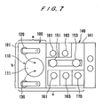
- FIG. 7 shows one conventional polishing apparatus having a polishing section 100 for polishing semiconductor wafers.
- the polishing section 100 comprises a turntable 110 having a polishing surface 111 and rotatable about its own axis at a predetermined speed, a top ring 120 for holding a semiconductor wafer to rotate the semiconductor wafer at a predetermined speed and pressing the semiconductor wafer against the polishing surface 111 of the turntable 110 for thereby polishing a surface of the semiconductor wafer, and a dressing tool 130 for dressing the polishing surface 111 to regenerate the polishing surface in contact therewith.
- the turntable 110, the top ring 120, and the dressing tool 130 are housed in a single chamber 101.
- the polishing apparatus also has a cleaning section 140 for conveying the semiconductor wafers and cleaning the semiconductor wafers.
- the cleaning section 140 comprises two workpiece conveying robots 151, 153 for taking a semiconductor wafer out of a cassette and delivering the semiconductor wafer to the polishing section 100, primary and secondary cleaning devices 161, 163 for cleaning the semiconductor wafer which has been polished, a drying device 170 for drying the semiconductor wafer which has been cleaned, and two workpiece reversing devices 181, 183 for reversing the semiconductor wafer upside down.
- the workpiece conveying robots 151, 153, the primary and secondary cleaning devices 161, 163, the drying device 170, and the workpiece reversing devices 181, 183 are housed in a single chamber 141.
- top ring 120 a polishing cloth which provides the polishing surface 111 of the turntable 110, and a dressing element such as a dresser brush or a diamond grain layer on the dressing tool 130 are expendable articles or parts that should be replaced with new ones periodically in maintenance activities.
- the cleaning devices 161, 163 also have expendable articles including cleaning brushes and sponge elements which are also required to be replaced with new ones periodically in maintenance activities.
- the above maintenance activities signify not service repair activities for repairing the polishing section 100 and the cleaning section 140 in the event of malfunctions or failures, but periodical replacement routines for replacing expendable articles or parts.
- a side face "a” for maintenance such as replacement of the parts of the top ring 120
- a side face "b” for maintenance such as replacement of the polishing cloth constituting the polishing surface 111
- a side face "c” for maintenance such as replacement of the dresser brush of the dressing tool 130 and the cleaning brushes of the cleaning devices 161, 163.
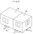
- FIG. 8 is a perspective view showing an outer appearance of the conventional polishing apparatus shown in FIG. 7. As shown in FIG. 8, the polishing section 100 and the cleaning section 140 are housed in respective chambers in the form of a rectangular parallelepiped.
- the polishing section 100 and the cleaning section 140 have a number of pipes 171, 181 extending from side walls of the chambers for supplying liquid to and discharging liquid from the various units and machines in the polishing section 100 and the cleaning section 140.
- the pipes 171, 181 extend vertically through a floor 180 into a machinery room (not shown) below the floor 180, and are connected to various devices in the machinery room.
- the installation work of the polishing apparatus on the floor 180 is troublesome and time-consuming because the floor 180 has to be drilled to make holes for insertion of the pipes 171, 181.
- the pipes 171, 181 project from the side walls of the chambers into passages around the chambers and tend to obstruct operators walking along the passages. Therefore, the pipes 171, 181 make the polishing apparatus take up a more installation space than would be required by their physical size. In addition, the pipes 171, 181 are not sightly to external view.
- Another object of the present invention is to provide a polishing apparatus which can be easily maintained, transported and installed, does not obstruct operators walking along passages therearound, and is sightly to external view.
- a polishing apparatus according to a first embodiment of the present invention will be described below with reference to FIGS. 1 and 2.
- a polishing apparatus comprises a polishing section 30 for polishing a workpiece such as a semiconductor wafer, and a cleaning section 50 for cleaning the workpiece which has been polished in the polishing section 30.
- the polishing section 30 comprises a central turntable 33, a polishing unit 37 disposed on one side of the turntable 33 and having a top ring 35, a dressing unit 41 disposed on the other side of the turntable 33 and having a dressing tool 39, and a workpiece transfer device 43 for transferring the workpiece between the top ring 35 and the workpiece transfer device 43.
- the turntable 33, the polishing unit 37, the dressing unit 41, and the workpiece transfer unit 43 are all housed in a single chamber 47 which is enclosed by walls.
- top ring 35 is shown as being in a maintenance position therefor, and the dressing tool 39 is also shown as being in a maintenance position therefor.
- the top ring 35 and the dressing tool 39 are in their respective maintenance positions, they are positioned closely to a side face A of the polishing section 30.
- the polishing surface 34 of the turntable 33 is also positioned closely to the side face A.
- a door (not shown) for maintenance is provided at the side face A.
- the cleaning section 50 comprises a pair of central workpiece conveying robots 51, 53 movable in the directions indicated by the arrow C, primary and secondary cleaning devices 55, 57 and a spinning drier 59 which are arranged in an array on one side of the workpiece conveying robots 51, 53, and two workpiece reversing devices 61, 63 which are arranged in an array on the other side of the workpiece conveying robots 51, 53.
- the workpiece conveying robots 51, 53, the primary and secondary cleaning devices 55, 57 and the spinning drier 59, and the workpiece reversing devices 61, 63 are housed in a single chamber 67 which is enclosed by walls.
- the primary and secondary cleaning devices 55, 57 and the spinning drier 59 are positioned closely to a side face A' of the cleaning section 50.
- a door (not shown) for maintenance is provided at the side face A'.
- the side face A' of the cleaning section 50 is aligned with or lies flush with the side face A of the polishing apparatus 30. That is, the polishing section 30 and the cleaning section 50 have a common side face comprising the side faces A and A' for approaching an interior thereof for maintenance of the polishing section 30 and the cleaning section 50.
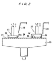
- FIG. 2 shows the polishing section 30 having the turntable 33, the top ring unit 37 and the dressing unit 41.
- the top ring unit 37 has the top ring 35 for supporting a semiconductor wafer W and pressing the semiconductor wafer W against the turntable 33.
- the turntable 33 is rotatable about its own axis as indicated by an arrow by a motor (not shown) which is coupled to the turntable 33.
- a polishing cloth 21 constituting a polishing surface 34 is attached to an upper surface of the turntable 33.
- the top ring 35 is coupled to a motor (not shown) and also to a lifting/lowering cylinder (not shown).
- the top ring 35 is vertically movable and rotatable about its own axis as indicated by the arrows by the motor and the lifting/lowering cylinder.
- the top ring 35 can therefore press the semiconductor wafer W against the polishing cloth 21 under a desired pressure.
- the semiconductor wafer W is attached to a lower surface of the top ring 35 under a vacuum or the like.
- a guide ring 36 is mounted on the outer circumferential edge of the lower surface of the top ring 35 for preventing the semiconductor wafer W from being disengaged from the top ring 35.
- An abrasive liquid is supplied through a supply pipe 23 onto the polishing cloth 21.
- a dressing unit 41 comprises a dressing tool 39 which is positioned above the turntable 33 in diametrically opposite relation to the top ring 35.
- a dressing liquid is supplied through a supply pipe 24 onto the polishing cloth 21.
- the dressing tool 39 is coupled to a motor (not shown) and also to a lifting/lowering cylinder (not shown).
- the dressing tool 39 is vertically movable and rotatable about its own axis as indicated by the arrows by the motor and the lifting/lowering cylinder.
- the dressing tool 39 has a dressing element 39a composed of, for example, nylon brush, or a diamond grain layer containing diamond grains on its lower surface.
- polishing apparatus comprising the polishing section 30 and the cleaning section 50 will be described below.
- the workpiece conveying robot 53 takes a semiconductor wafer out of the cassette 65, and transfers the semiconductor wafer to the workpiece reversing device 63. After the semiconductor wafer is reversed, i.e., turned upside down, by the workpiece reversing device 63, it is received by the workpiece conveying robot 51, and then placed onto the workpiece transfer device 43 through an opening formed in a partition between chambers by the workpiece conveying robot 51.
- the top ring 35 of the polishing unit 37 is angularly displaced as indicated by the dot-and-dash line to a position directly above the workpiece transfer device 43.
- the semiconductor wafer on the workpiece transfer device 43 is lifted to a position near a lower surface of the top ring 35, and then attached to the top ring 35 under vacuum developed by a vacuum pump or the like (not shown).
- the top ring 35 is moved over the turntable 33, and presses the semiconductor wafer against the polishing surface 34 on the turntable 33. While the turntable 33 and the top ring 35 are rotated independently of each other, the lower surface of the semiconductor wafer is polished to a flat mirror finish. At this time, the abrasive liquid is supplied through the supply pipe 23 onto the polishing surface 34. After the semiconductor wafer is polished, the top ring 35 is moved back over the workpiece transfer device 43, and transfers the polished semiconductor wafer onto the workpiece transfer device 43.
- the semiconductor wafer placed on the workpiece transfer device 43 is then held by the workpiece conveying robot 51, and transferred therefrom to the workpiece reversing device 61.
- the workpiece reversing device 61 reverses the semiconductor wafer.
- the reversed semiconductor wafer is transferred successively to the primary and secondary cleaning devices 55 and 57, and the spinning drier 59, whereby the semiconductor wafer is cleaned by cleaning liquid such as pure water and dried.
- the spinning drier 59 may have a function of cleaning and drying.
- the cleaned and dried semiconductor wafer is finally returned to the cassette 65 by the workpiece conveying robot 53.
- the dressing tool 39 of the dressing unit 41 is angularly moved over the turntable 33 as indicated by the dot-and-dash-line arrow, and then presses the dressing tool 39 against the polishing surface 34 for thereby dressing the polishing surface 34.
- pure water is supplied as dressing liquid through the supply pipe 24 onto the polishing surface 34.
- the polishing cloth 21 which provides the polishing surface 34 of the turntable 33 is also an expendable part and can easily be replaced by the person for maintenance from the side face A while the door for maintenance is being open.
- Cleaning brushes, sponge elements, and other parts of the primary and secondary cleaning devices 55, 57, and parts of the spinning drier 59 are also expendable parts, and can easily be replaced from the side face A' while the door for maintenance is being open.
- the first embodiment of the present invention offers the following advantages:
- the person for maintenance Since the side faces A and A' are aligned or lie flush with each other, the person for maintenance is required to move not a large distance but a short distance from one of the side faces A, A' to the other, while carrying tools and parts, when a plurality of parts units or machines are to be maintained for parts replacement. Therefore, the person for maintenance finds it easy to replace plural expendable parts.
- the other side faces than the side faces A and A' of the polishing apparatus comprising the polishing section 30 and the cleaning section 50 may be positioned closely to hindering objects such as walls or pillars. As a consequence, the installation space required to install the polishing apparatus therein may be relatively small in size.
- FIGS. 3 through 6 the parts which are structurally or functionally identical to the parts shown in FIGS. 1 and 2 are represented by the same reference numerals.
- the structure of the polishing section 30 and the cleaning section 50 in the second embodiment is identical to that of the polishing section 30 and the cleaning section 50 in the first embodiment.
- the chambers 47 and 67 which accommodate the various units and machines of the polishing section 30 and cleaning section 50, have respective side faces 49 and 69 joined to each other.
- the side face 69 of the chamber 67 is longer than the side face 49 of the chamber 47, and hence includes an exposed portion which does not face the side face 49 of the chamber 47.
- An elongated rectangular space 80 indicated by the dotted line in FIG. 3 is provided in front of the exposed portion of the side face 69 and alongside of other side face 48 of the chamber 47, for accommodating a collection of pipes projecting from the chambers 47 and 67.
- the units and machines of the polishing section 30 and the cleaning section 50 are positioned in the chambers 47, 67 in order to make the side faces 49, 69 different in length from each other for thereby providing the space 80.
- the pipes 10 and 20 then extend vertically through holes defined in a floor 70 (see FIG. 6) into a machinery room 90 below the floor 70 of a clean room 200 which accommodates the polishing section 30 and the cleaning section 50.
- the machinery room 90 houses various machines 91.
- FIG. 5 shows in an enlarged scale the pipes 10-1 - 10-11 and the pipes 20-1 - 20-5 which are positioned in the space 80 and extend vertically through the floor 70.
- the pipes 10-2, 10-4 and 10-6 serve as inlets of abrasive liquid circulation pipes for supplying the abrasive liquid from the machines 91 to the polishing surface 34 of the turntable 33.
- the pipes 10-1, 10-3 and 10-5 serve as outlets of the abrasive liquid circulation pipes for returning the abrasive liquid which has not been used to the machines 91.
- the pipe 10-7 serves as an abrasive liquid drain pipe for draining the abrasive liquid which has been used on the abrasive surface 34 and also draining pure water.
- the pipe 10-8 serves as a pure water supply pipe for supplying pure water for dressing process.
- the pipe 10-9 serves as a leakage liquid drain pipe for draining liquid which has leaked from the various units of the polishing section 30.
- the pipe 10-10 serves as an outlet of a cooling water circulation pipe for supplying cooling water to the turntable 33 or the like.
- the pipe 10-11 serves as an inlet of the cooling water circulation pipe.
- the pipe 20-1 serves as a pure water supply pipe for supplying pure water to the primary and secondary cleaning devices 55, 57, the spinning drier 59 and the workpiece reversing device 61.
- the pipes 20-2, 20-3 serve as drain pipes for draining various liquid which has been used.
- the pipe 20-4 serves as an inlet of a cleaning liquid circulation pipe for supplying cleaning liquid to the primary and secondary cleaning devices 55, 57.
- the pipe 20-5 serves as an outlet of the cleaning liquid circulation pipe.
- FIG. 6 shows an arrangement of the polishing apparatus and the machinery room 90.
- the polishing apparatus is installed in the clean room 200.
- the machinery room 90 is disposed below the floor 70 on which the polishing apparatus is installed.
- the various machines 91 housed in the machinery room 90 include an abrasive liquid supply device for supplying and circulating the abrasive liquid to the polishing section 30, a waste liquid treatment device for treating waste liquid discharged from the polishing section 30 and the cleaning section 50, and a cooling water supply device for supplying the cooling water to the polishing section 30.
- the pipes 10, 20 extending downwardly through the floor 70 into the machinery room 90 are connected to the machines 91 in the machinery room 90.
- the pipes 10, 20 which project from the polishing section 30 and the cleaning section 50 at the side faces 48, 69 of the chambers 47, 67 are collected in the space 80.
- These pipes 10, 20 do not project from other side faces of the polishing section 30 and the cleaning section 50, and hence maintenance of the polishing section 30 and the cleaning section 50 can be easily performed at those other side faces.
- the space 80 is positioned at a recess jointly defined by the side faces 48, 69 of the chambers 47, 67, the pipes 10, 20 do not project into passages around the polishing section 30 and the cleaning section 50.
- the projecting pipes 10, 20 in the space 80 may be covered with a step-like plate 110.
- the step-like plate 110 thus mounted in position may be used as a footstep, thus providing a space thereabove as a free space available for some purposes, e.g., for maintenance of the polishing section 30.
- the step-like plate 110 is also effective to conceal the pipes 10, 20 from external view, thus providing a sightly appearance.
- the second embodiment of the present invention offers the following advantages:
- the pipes from the polishing section and the cleaning section are collected at a single location, the pipes do not present obstacles when the polishing apparatus is transported. Further, the through holes for inserting the pipes into the downstairs machinery room can be formed at a single location, and thus the installation work of the polishing apparatus can be easily carried out.
- the space for collecting the pipes is provided at a recess jointly defined by the polishing section and the cleaning section, the pipes do not project into passages around the polishing section and the cleaning section, and hence do not obstruct operators walking therearound.
- a space above the step-like plate can be utilized as a free space available for some purposes, and the step-like plate can conceal the pipes from external view to thus provide a sightly appearance.
- the polishing apparatus comprises a polishing section and a cleaning section housed in each chamber
- the partition between two sections may be omitted. That is, the polishing section and the cleaning section may be housed in a common housing.
- the invention relates to a polishing apparatus for polishing a surface of a workpiece comprising:
Landscapes
- Engineering & Computer Science (AREA)
- Mechanical Engineering (AREA)
- Finish Polishing, Edge Sharpening, And Grinding By Specific Grinding Devices (AREA)
- Mechanical Treatment Of Semiconductor (AREA)
Abstract
Description
- The present invention relates to a polishing apparatus for polishing a workpiece such as a semiconductor wafer to a flat mirror finish, and more particularly to a polishing apparatus having an easy maintenance characteristic.
- Recent rapid progress in semiconductor device integration demands smaller and smaller wiring patterns or interconnections and also narrower spaces between interconnections which connect active areas. One of the processes available for forming such interconnection is photolithography. Though the photolithographic process can form interconnections that are at most 0.5 µm wide, it requires that surfaces on which pattern images are to be focused by a stepper be as flat as possible because the depth of focus of the optical system is relatively small.
- It is therefore necessary to make the surfaces of semiconductor wafers flat for photolithography. One customary way of flattening the surfaces of semiconductor wafers is to polish them with a polishing apparatus, and such a process is called Chemical Mechanical polishing.
- FIG. 7 shows one conventional polishing apparatus having a
polishing section 100 for polishing semiconductor wafers. Thepolishing section 100 comprises aturntable 110 having apolishing surface 111 and rotatable about its own axis at a predetermined speed, atop ring 120 for holding a semiconductor wafer to rotate the semiconductor wafer at a predetermined speed and pressing the semiconductor wafer against thepolishing surface 111 of theturntable 110 for thereby polishing a surface of the semiconductor wafer, and adressing tool 130 for dressing thepolishing surface 111 to regenerate the polishing surface in contact therewith. Theturntable 110, thetop ring 120, and thedressing tool 130 are housed in asingle chamber 101. - The polishing apparatus also has a
cleaning section 140 for conveying the semiconductor wafers and cleaning the semiconductor wafers. Thecleaning section 140 comprises twoworkpiece conveying robots polishing section 100, primary andsecondary cleaning devices drying device 170 for drying the semiconductor wafer which has been cleaned, and twoworkpiece reversing devices workpiece conveying robots secondary cleaning devices drying device 170, and theworkpiece reversing devices single chamber 141. - Certain parts of the
top ring 120, a polishing cloth which provides thepolishing surface 111 of theturntable 110, and a dressing element such as a dresser brush or a diamond grain layer on thedressing tool 130 are expendable articles or parts that should be replaced with new ones periodically in maintenance activities. - The
cleaning devices - The above maintenance activities signify not service repair activities for repairing the
polishing section 100 and thecleaning section 140 in the event of malfunctions or failures, but periodical replacement routines for replacing expendable articles or parts. - Heretofore, the maintenance activities which involve parts replacement have been carried out in three different side faces, i.e., a side face "a" for maintenance such as replacement of the parts of the
top ring 120, a side face "b" for maintenance such as replacement of the polishing cloth constituting thepolishing surface 111, and a side face "c" for maintenance such as replacement of the dresser brush of thedressing tool 130 and the cleaning brushes of thecleaning devices - Because of these three side faces "a", "b" and "c" involved, it has been necessary to keep empty spaces respectively in front of the side faces "a", "b" and "c" to allow approach to the side faces "a", "b" and "c" for maintenance such as the replacement of parts. Consequently, any one of these side faces "a", "b" and "c" cannot be positioned closely to other hindering objects such as walls or pillars, with the result that a large installation space has been required for the installation of the polishing apparatus.
- When the polishing apparatus is to be maintained or serviced successively at the side faces "a", "b" and "c", the person for maintenance has to move from one side face to another while carrying tools and parts. Therefore, the maintenance work of the polishing apparatus has been troublesome and time-consuming.
- FIG. 8 is a perspective view showing an outer appearance of the conventional polishing apparatus shown in FIG. 7. As shown in FIG. 8, the
polishing section 100 and thecleaning section 140 are housed in respective chambers in the form of a rectangular parallelepiped. - The
polishing section 100 and thecleaning section 140 have a number ofpipes polishing section 100 and thecleaning section 140. Thepipes floor 180 into a machinery room (not shown) below thefloor 180, and are connected to various devices in the machinery room. - Heretofore, the
pipes - Since the
pipes polishing section 100 and thecleaning section 140 are maintained, or transported for installation thereof. When thepipes - The installation work of the polishing apparatus on the
floor 180 is troublesome and time-consuming because thefloor 180 has to be drilled to make holes for insertion of thepipes - The
pipes pipes pipes - It is therefore an object of the present invention to provide a polishing apparatus which allows the person for maintenance to easily perform maintenance activities such as replacement of various expendable articles or parts, and which can be installed in a relatively small installation space.
- Another object of the present invention is to provide a polishing apparatus which can be easily maintained, transported and installed, does not obstruct operators walking along passages therearound, and is sightly to external view.
- According to one aspect of the present invention, there is provided a polishing apparatus for polishing a surface of a workpiece comprising: a turntable having a polishing surface; a top ring for holding a workpiece and pressing the workpiece against the polishing surface of the turntable to polish the workpiece, the top ring being movable to a first maintenance position therefor; and a dressing tool for dressing the polishing surface of the turntable, the dressing tool being movable to a second maintenance position therefor; wherein the top ring, the polishing surface of the turntable, and the dressing tool are housed in a first chamber having a plurality of side faces, and the polishing surface, the first maintenance position and the second maintenance position are positioned closely to one of the side faces, and the one of the side faces serves as a first maintenance face for approaching the polishing surface, the first maintenance position and the second maintenance position for maintenance of the polishing surface, said top ring and the dressing tool.
- According to another aspect of the present invention, there is provided a polishing apparatus for polishing a surface of a workpiece comprising: a polishing section housed in a first chamber for polishing a surface of a workpiece; and a cleaning section housed in a second chamber for cleaning the workpiece which has been polished, the first chamber having a first side face and the second chamber having a second side face joined to the first side face, the second side face being longer than the first side face to define an exposed portion which does not face the first side face, the first and second chambers jointly defining a space in front of the exposed portion and alongside of other side face of the first chamber; wherein the polishing section and the cleaning section have pipes extending from the exposed portion of the second side face and the other side face of the first chamber into the space, respectively.
- The above and other objects, features, and advantages of the present invention will become apparent from the following description when taken in conjunction with the accompanying drawings which illustrate preferred embodiments of the present invention by way of examples.
-
- FIG. 1 is a schematic plan view of a polishing apparatus according to a first embodiment of the present invention;
- FIG. 2 is a cross-sectional view of a polishing section of the polishing apparatus;
- FIG. 3 is a schematic plan view of a polishing apparatus according to a second embodiment of the present invention;
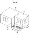
- FIG. 4 is a perspective view showing an outward appearance of the polishing apparatus according to the second embodiment of the present invention;
- FIG. 5 is a schematic plan view showing an arrangement of pipes according to the second embodiment of the present invention;
- FIG. 6 is a schematic vertical cross-sectional view showing an arrangement of a polishing apparatus and a machinery room;
- FIG. 7 is a schematic plan view of a conventional polishing apparatus; and
- FIG. 8 is a perspective view showing an outward appearance of the conventional polishing apparatus shown in FIG. 7.
- A polishing apparatus according to a first embodiment of the present invention will be described below with reference to FIGS. 1 and 2.
- As shown in FIG. 1, a polishing apparatus comprises a
polishing section 30 for polishing a workpiece such as a semiconductor wafer, and acleaning section 50 for cleaning the workpiece which has been polished in thepolishing section 30. Thepolishing section 30 comprises acentral turntable 33, apolishing unit 37 disposed on one side of theturntable 33 and having atop ring 35, adressing unit 41 disposed on the other side of theturntable 33 and having adressing tool 39, and aworkpiece transfer device 43 for transferring the workpiece between thetop ring 35 and theworkpiece transfer device 43. Theturntable 33, thepolishing unit 37, thedressing unit 41, and theworkpiece transfer unit 43 are all housed in asingle chamber 47 which is enclosed by walls. - In FIG. 1, the
top ring 35 is shown as being in a maintenance position therefor, and thedressing tool 39 is also shown as being in a maintenance position therefor. When thetop ring 35 and thedressing tool 39 are in their respective maintenance positions, they are positioned closely to a side face A of thepolishing section 30. Thepolishing surface 34 of theturntable 33 is also positioned closely to the side face A. - In the illustrated embodiment, only the side face A of the
polishing section 30, among a plurality of side faces of thechamber 47, serves as a maintenance face which is easily approachable for maintenance of thepolishing section 30. A door (not shown) for maintenance is provided at the side face A. - The
cleaning section 50 comprises a pair of centralworkpiece conveying robots secondary cleaning devices drier 59 which are arranged in an array on one side of theworkpiece conveying robots workpiece reversing devices workpiece conveying robots workpiece conveying robots secondary cleaning devices drier 59, and theworkpiece reversing devices single chamber 67 which is enclosed by walls. - The primary and
secondary cleaning devices drier 59 are positioned closely to a side face A' of thecleaning section 50. In the illustrated embodiment, only the side face A' of thecleaning section 50, among a plurality of side faces of thechamber 67, serves as a maintenance face which is easily approachable for maintenance of thecleaning section 50. A door (not shown) for maintenance is provided at the side face A'. The side face A' of thecleaning section 50 is aligned with or lies flush with the side face A of thepolishing apparatus 30. That is, thepolishing section 30 and thecleaning section 50 have a common side face comprising the side faces A and A' for approaching an interior thereof for maintenance of thepolishing section 30 and thecleaning section 50. - FIG. 2 shows the polishing
section 30 having theturntable 33, thetop ring unit 37 and thedressing unit 41. Thetop ring unit 37 has thetop ring 35 for supporting a semiconductor wafer W and pressing the semiconductor wafer W against theturntable 33. Theturntable 33 is rotatable about its own axis as indicated by an arrow by a motor (not shown) which is coupled to theturntable 33. A polishingcloth 21 constituting a polishingsurface 34 is attached to an upper surface of theturntable 33. - The
top ring 35 is coupled to a motor (not shown) and also to a lifting/lowering cylinder (not shown). Thetop ring 35 is vertically movable and rotatable about its own axis as indicated by the arrows by the motor and the lifting/lowering cylinder. Thetop ring 35 can therefore press the semiconductor wafer W against the polishingcloth 21 under a desired pressure. The semiconductor wafer W is attached to a lower surface of thetop ring 35 under a vacuum or the like. Aguide ring 36 is mounted on the outer circumferential edge of the lower surface of thetop ring 35 for preventing the semiconductor wafer W from being disengaged from thetop ring 35. An abrasive liquid is supplied through asupply pipe 23 onto the polishingcloth 21. - A
dressing unit 41 comprises adressing tool 39 which is positioned above theturntable 33 in diametrically opposite relation to thetop ring 35. A dressing liquid is supplied through asupply pipe 24 onto the polishingcloth 21. The dressingtool 39 is coupled to a motor (not shown) and also to a lifting/lowering cylinder (not shown). The dressingtool 39 is vertically movable and rotatable about its own axis as indicated by the arrows by the motor and the lifting/lowering cylinder. The dressingtool 39 has adressing element 39a composed of, for example, nylon brush, or a diamond grain layer containing diamond grains on its lower surface. - Operation of the polishing apparatus comprising the polishing
section 30 and thecleaning section 50 will be described below. - When a
wafer cassette 65 which houses a plurality of semiconductor wafers to be polished is set in a position as shown in FIG. 1, theworkpiece conveying robot 53 takes a semiconductor wafer out of thecassette 65, and transfers the semiconductor wafer to theworkpiece reversing device 63. After the semiconductor wafer is reversed, i.e., turned upside down, by theworkpiece reversing device 63, it is received by theworkpiece conveying robot 51, and then placed onto theworkpiece transfer device 43 through an opening formed in a partition between chambers by theworkpiece conveying robot 51. - Thereafter, the
top ring 35 of the polishingunit 37 is angularly displaced as indicated by the dot-and-dash line to a position directly above theworkpiece transfer device 43. The semiconductor wafer on theworkpiece transfer device 43 is lifted to a position near a lower surface of thetop ring 35, and then attached to thetop ring 35 under vacuum developed by a vacuum pump or the like (not shown). - Then, the
top ring 35 is moved over theturntable 33, and presses the semiconductor wafer against the polishingsurface 34 on theturntable 33. While theturntable 33 and thetop ring 35 are rotated independently of each other, the lower surface of the semiconductor wafer is polished to a flat mirror finish. At this time, the abrasive liquid is supplied through thesupply pipe 23 onto the polishingsurface 34. After the semiconductor wafer is polished, thetop ring 35 is moved back over theworkpiece transfer device 43, and transfers the polished semiconductor wafer onto theworkpiece transfer device 43. - The semiconductor wafer placed on the
workpiece transfer device 43 is then held by theworkpiece conveying robot 51, and transferred therefrom to theworkpiece reversing device 61. Theworkpiece reversing device 61 reverses the semiconductor wafer. The reversed semiconductor wafer is transferred successively to the primary andsecondary cleaning devices cassette 65 by theworkpiece conveying robot 53. - After the semiconductor wafer is polished, the dressing
tool 39 of thedressing unit 41 is angularly moved over theturntable 33 as indicated by the dot-and-dash-line arrow, and then presses the dressingtool 39 against the polishingsurface 34 for thereby dressing the polishingsurface 34. At this time, pure water is supplied as dressing liquid through thesupply pipe 24 onto the polishingsurface 34. - Parts of a mechanism on the
top ring 35 for holding the semiconductor wafer, the dresser element and other parts on thedressing tool 39 are expendable parts. These expendable parts of thetop ring 35 and thedressing tool 39 are replaced with new parts while thetop ring 35 and thedressing tool 39 are in their respective maintenance positions shown in FIG. 1. Since these maintenance positions are located closely to the side face A, the parts can easily be replaced from the side face A while the door for maintenance is being open. - The polishing
cloth 21 which provides the polishingsurface 34 of theturntable 33 is also an expendable part and can easily be replaced by the person for maintenance from the side face A while the door for maintenance is being open. - Cleaning brushes, sponge elements, and other parts of the primary and
secondary cleaning devices - As described above, the first embodiment of the present invention offers the following advantages:
- Since the side faces A and A' are aligned or lie flush with each other, the person for maintenance is required to move not a large distance but a short distance from one of the side faces A, A' to the other, while carrying tools and parts, when a plurality of parts units or machines are to be maintained for parts replacement. Therefore, the person for maintenance finds it easy to replace plural expendable parts.
- The other side faces than the side faces A and A' of the polishing apparatus comprising the polishing
section 30 and thecleaning section 50 may be positioned closely to hindering objects such as walls or pillars. As a consequence, the installation space required to install the polishing apparatus therein may be relatively small in size. - Next, a polishing apparatus according to a second embodiment of the present invention will be described below with reference to FIG. 3 through 6. In FIGS. 3 through 6, the parts which are structurally or functionally identical to the parts shown in FIGS. 1 and 2 are represented by the same reference numerals.
- The structure of the polishing
section 30 and thecleaning section 50 in the second embodiment is identical to that of the polishingsection 30 and thecleaning section 50 in the first embodiment. - As shown in FIG. 3, in this embodiment, the
chambers section 30 andcleaning section 50, have respective side faces 49 and 69 joined to each other. - The side face 69 of the
chamber 67 is longer than theside face 49 of thechamber 47, and hence includes an exposed portion which does not face theside face 49 of thechamber 47. An elongatedrectangular space 80 indicated by the dotted line in FIG. 3 is provided in front of the exposed portion of theside face 69 and alongside of other side face 48 of thechamber 47, for accommodating a collection of pipes projecting from thechambers - In other words, the units and machines of the polishing
section 30 and thecleaning section 50 are positioned in thechambers space 80. - Pipes 10 (10-1 - 10-11 in FIG. 5) extending outwardly from the polishing
section 30 project horizontally from theside face 48 of thechamber 47 into thespace 80, and pipes 20 (20-1 - 20-5 in FIG. 5) extending outwardly from thecleaning section 50 project horizontally from the exposed portion of theside face 69 of thechamber 67 into thespace 80. That is, thepipes space 80. - The
pipes machinery room 90 below thefloor 70 of aclean room 200 which accommodates the polishingsection 30 and thecleaning section 50. Themachinery room 90 housesvarious machines 91. - FIG. 5 shows in an enlarged scale the pipes 10-1 - 10-11 and the pipes 20-1 - 20-5 which are positioned in the
space 80 and extend vertically through thefloor 70. - In FIG. 5, the pipes 10-2, 10-4 and 10-6 serve as inlets of abrasive liquid circulation pipes for supplying the abrasive liquid from the
machines 91 to the polishingsurface 34 of theturntable 33. The pipes 10-1, 10-3 and 10-5 serve as outlets of the abrasive liquid circulation pipes for returning the abrasive liquid which has not been used to themachines 91. The pipe 10-7 serves as an abrasive liquid drain pipe for draining the abrasive liquid which has been used on theabrasive surface 34 and also draining pure water. The pipe 10-8 serves as a pure water supply pipe for supplying pure water for dressing process. The pipe 10-9 serves as a leakage liquid drain pipe for draining liquid which has leaked from the various units of the polishingsection 30. The pipe 10-10 serves as an outlet of a cooling water circulation pipe for supplying cooling water to theturntable 33 or the like. The pipe 10-11 serves as an inlet of the cooling water circulation pipe. - The pipe 20-1 serves as a pure water supply pipe for supplying pure water to the primary and
secondary cleaning devices workpiece reversing device 61. The pipes 20-2, 20-3 serve as drain pipes for draining various liquid which has been used. The pipe 20-4 serves as an inlet of a cleaning liquid circulation pipe for supplying cleaning liquid to the primary andsecondary cleaning devices - FIG. 6 shows an arrangement of the polishing apparatus and the
machinery room 90. As shown in FIG. 6, the polishing apparatus is installed in theclean room 200. Themachinery room 90 is disposed below thefloor 70 on which the polishing apparatus is installed. Thevarious machines 91 housed in themachinery room 90 include an abrasive liquid supply device for supplying and circulating the abrasive liquid to thepolishing section 30, a waste liquid treatment device for treating waste liquid discharged from the polishingsection 30 and thecleaning section 50, and a cooling water supply device for supplying the cooling water to thepolishing section 30. - The
pipes floor 70 into themachinery room 90 are connected to themachines 91 in themachinery room 90. Thepipes section 30 and thecleaning section 50 at the side faces 48, 69 of thechambers space 80. Thesepipes section 30 and thecleaning section 50, and hence maintenance of the polishingsection 30 and thecleaning section 50 can be easily performed at those other side faces. - Since the
space 80 is positioned at a recess jointly defined by the side faces 48, 69 of thechambers pipes section 30 and thecleaning section 50. - As shown in FIGS. 4 and 6, the projecting
pipes space 80 may be covered with a step-like plate 110. The step-like plate 110 thus mounted in position may be used as a footstep, thus providing a space thereabove as a free space available for some purposes, e.g., for maintenance of the polishingsection 30. The step-like plate 110 is also effective to conceal thepipes - As is apparent from the above description, the second embodiment of the present invention offers the following advantages:
- Since the pipes from the polishing section and the cleaning section are collected at a single location, maintenance for various devices in the polishing section and the cleaning section can be easily performed from other side faces where the pipes do not exist.
- Since the pipes from the polishing section and the cleaning section are collected at a single location, the pipes do not present obstacles when the polishing apparatus is transported. Further, the through holes for inserting the pipes into the downstairs machinery room can be formed at a single location, and thus the installation work of the polishing apparatus can be easily carried out.
- Since the space for collecting the pipes is provided at a recess jointly defined by the polishing section and the cleaning section, the pipes do not project into passages around the polishing section and the cleaning section, and hence do not obstruct operators walking therearound.
- In the case where the step-like plate is provided in the space for collecting the pipes, a space above the step-like plate can be utilized as a free space available for some purposes, and the step-like plate can conceal the pipes from external view to thus provide a sightly appearance.
- In the above embodiment, although the polishing apparatus comprises a polishing section and a cleaning section housed in each chamber, the partition between two sections may be omitted. That is, the polishing section and the cleaning section may be housed in a common housing.
- Although a certain preferred embodiment of the present invention has been shown and described in detail, it should be understood that various changes and modifications may be made therein without departing from the scope of the appended claims.
- According to its broadest aspect the invention relates to a polishing apparatus for polishing a surface of a workpiece comprising:
- a turntable having a polishing surface;
- a ring for holding a workpiece, said ring being movable to a first maintenance position therefor; and
- a dressing tool for dressing said polishing surface of said turntable, said dressing tool being movable to a second maintenance position therefor.
Claims (9)
- A polishing apparatus for polishing a surface of a workpiece comprising:a turntable having a polishing surface;a top ring for holding a workpiece and pressing the workpiece against said polishing surface of said turntable to polish the workpiece, said top ring being movable to a first maintenance position therefor; anda dressing tool for dressing said polishing surface of said turntable, said dressing tool being movable to a second maintenance position therefor;
wherein said top ring, said polishing surface of said turntable, and said dressing tool are housed in a first chamber having a plurality of side faces, and said polishing surface, said first maintenance position and said second maintenance position are positioned closely to one of said side faces, and said one of said side faces serves as a first maintenance face for approaching said polishing surface, said first maintenance position and said second maintenance position for maintenance of said polishing surface, said top ring and said dressing tool. - A polishing apparatus according to claim 1, further comprising:a cleaning device for cleaning a workpiece which has been polished;
wherein said cleaning device is housed in a second chamber having a plurality of side faces and positioned closely to one of said side faces of said second chamber, said one of said side faces of said second chamber serves as a second maintenance face for approaching said cleaning device for maintenance of said cleaning device, and said second maintenance face is oriented in the same direction as said first maintenance face. - A polishing apparatus for polishing a surface of a workpiece comprising:a polishing section housed in a first chamber for polishing a surface of a workpiece; anda cleaning section housed in a second chamber for cleaning the workpiece which has been polished, said first chamber having a first side face and said second chamber having a second side face joined to said first side face, said second side face being longer than said first side face to define an exposed portion which does not face said first side face, said first and second chambers jointly defining a space in front of said exposed portion and alongside of other side face of said first chamber;
wherein said polishing section and said cleaning section have pipes extending from said exposed portion of said second side face and said other side face of said first chamber into said space, respectively. - A polishing apparatus according to claim 3, further comprising a plate disposed in covering relation to said pipes extending into said space.
- A polishing apparatus according to claim 3, wherein said polishing section and said cleaning section are mounted on a floor, and said pipes extends from said space downwardly through said floor into a machinery room disposed below said floor and are connected to devices housed in said machinery room.
- A polishing apparatus for polishing a surface of a workpiece comprising:a polishing section for polishing a surface of a workpiece; anda cleaning section for cleaning the workpiece which has been polished;
wherein said polishing section and said cleaning section have respective side faces which are oriented in the same direction, for approaching an interior of said polishing section and said cleaning section for maintenance of said polishing section and said cleaning section. - A polishing apparatus according to claim 6, wherein said polishing section is housed in a first chamber having a first side face, said cleaning section is housed in a second chamber having a second side face joined to said first side face, said second side face is longer than said first side face to define an exposed portion which does not face said first side face, and said first and second chambers jointly define a space in front of said exposed portion and alongside of other side face of said first chamber; and
wherein said polishing section and said cleaning section have pipes extending from said exposed portion of said second side face and said other side face of said first chamber into said space, respectively. - A polishing apparatus for polishing a surface of a workpiece comprising:a housing;a polishing section housed in said housing for polishing a surface of a workpiece; anda cleaning section housed in said housing for cleaning the workpiece which has been polished;
wherein maintenance of said polishing section and maintenance of said cleaning section are performed from one side of said housing. - A polishing apparatus for polishing a surface of a workpiece comprising:a turntable having a polishing surface;a ring for holding a workpiece, said ring being movable to a first maintenance position therefor; anda dressing tool for dressing said polishing surface of said turntable, said dressing tool being movable to a second maintenance position therefor.
Applications Claiming Priority (6)
| Application Number | Priority Date | Filing Date | Title |
|---|---|---|---|
| JP130987/96 | 1996-04-26 | ||
| JP13098796 | 1996-04-26 | ||
| JP13098796A JPH09295262A (en) | 1996-04-26 | 1996-04-26 | Polishing equipment |
| JP15760896 | 1996-05-28 | ||
| JP15760896A JPH09320997A (en) | 1996-05-28 | 1996-05-28 | Piping structure for polishing apparatus and cleaning apparatus |
| JP157608/96 | 1996-05-28 |
Publications (3)
| Publication Number | Publication Date |
|---|---|
| EP0803326A2 true EP0803326A2 (en) | 1997-10-29 |
| EP0803326A3 EP0803326A3 (en) | 1998-04-15 |
| EP0803326B1 EP0803326B1 (en) | 2002-10-02 |
Family
ID=26465955
Family Applications (1)
| Application Number | Title | Priority Date | Filing Date |
|---|---|---|---|
| EP97106937A Expired - Lifetime EP0803326B1 (en) | 1996-04-26 | 1997-04-25 | Polishing apparatus |
Country Status (4)
| Country | Link |
|---|---|
| US (1) | US6227954B1 (en) |
| EP (1) | EP0803326B1 (en) |
| KR (1) | KR100415406B1 (en) |
| DE (1) | DE69715952T2 (en) |
Cited By (2)
| Publication number | Priority date | Publication date | Assignee | Title |
|---|---|---|---|---|
| US6612912B2 (en) | 1998-08-11 | 2003-09-02 | Hitachi, Ltd. | Method for fabricating semiconductor device and processing apparatus for processing semiconductor device |
| US9245783B2 (en) | 2013-05-24 | 2016-01-26 | Novellus Systems, Inc. | Vacuum robot with linear translation carriage |
Families Citing this family (1)
| Publication number | Priority date | Publication date | Assignee | Title |
|---|---|---|---|---|
| US6409580B1 (en) * | 2001-03-26 | 2002-06-25 | Speedfam-Ipec Corporation | Rigid polishing pad conditioner for chemical mechanical polishing tool |
Family Cites Families (10)
| Publication number | Priority date | Publication date | Assignee | Title |
|---|---|---|---|---|
| JPS63207559A (en) | 1987-02-19 | 1988-08-26 | Disco Abrasive Syst Ltd | Wafer automatic grinding equipment |
| US5036625A (en) | 1988-12-07 | 1991-08-06 | Anatoly Gosis | Lapping plate for a lapping and polishing machine |
| JPH0615565A (en) * | 1991-12-18 | 1994-01-25 | Shin Etsu Handotai Co Ltd | Wafer automatic lapping device |
| US5733171A (en) * | 1996-07-18 | 1998-03-31 | Speedfam Corporation | Apparatus for the in-process detection of workpieces in a CMP environment |
| KR100390293B1 (en) | 1993-09-21 | 2003-09-02 | 가부시끼가이샤 도시바 | Polishing device |
| JP3326642B2 (en) * | 1993-11-09 | 2002-09-24 | ソニー株式会社 | Substrate post-polishing treatment method and polishing apparatus used therefor |
| US5679060A (en) * | 1994-07-14 | 1997-10-21 | Silicon Technology Corporation | Wafer grinding machine |
| US5655954A (en) * | 1994-11-29 | 1997-08-12 | Toshiba Kikai Kabushiki Kaisha | Polishing apparatus |
| DE19544328B4 (en) * | 1994-11-29 | 2014-03-20 | Ebara Corp. | polisher |
| US5679055A (en) * | 1996-05-31 | 1997-10-21 | Memc Electronic Materials, Inc. | Automated wafer lapping system |
-
1997
- 1997-04-25 DE DE69715952T patent/DE69715952T2/en not_active Expired - Fee Related
- 1997-04-25 EP EP97106937A patent/EP0803326B1/en not_active Expired - Lifetime
- 1997-04-25 KR KR1019970015480A patent/KR100415406B1/en not_active Expired - Lifetime
- 1997-04-25 US US08/845,423 patent/US6227954B1/en not_active Expired - Lifetime
Cited By (2)
| Publication number | Priority date | Publication date | Assignee | Title |
|---|---|---|---|---|
| US6612912B2 (en) | 1998-08-11 | 2003-09-02 | Hitachi, Ltd. | Method for fabricating semiconductor device and processing apparatus for processing semiconductor device |
| US9245783B2 (en) | 2013-05-24 | 2016-01-26 | Novellus Systems, Inc. | Vacuum robot with linear translation carriage |
Also Published As
| Publication number | Publication date |
|---|---|
| KR100415406B1 (en) | 2004-06-18 |
| EP0803326B1 (en) | 2002-10-02 |
| DE69715952T2 (en) | 2003-08-07 |
| US6227954B1 (en) | 2001-05-08 |
| DE69715952D1 (en) | 2002-11-07 |
| KR970077251A (en) | 1997-12-12 |
| EP0803326A3 (en) | 1998-04-15 |
Similar Documents
| Publication | Publication Date | Title |
|---|---|---|
| EP1642679B1 (en) | Polishing apparatus | |
| US7198552B2 (en) | Polishing apparatus | |
| US6966821B2 (en) | Method and apparatus for dry-in, dry-out polishing and washing of a semiconductor device | |
| EP0792721B1 (en) | Polishing apparatus | |
| EP0761387B1 (en) | Polishing apparatus | |
| US5655954A (en) | Polishing apparatus | |
| US7063600B2 (en) | Polishing apparatus | |
| EP0813932B1 (en) | Polishing apparatus having a cloth cartridge | |
| EP0803326A2 (en) | Polishing apparatus | |
| US5931723A (en) | Polishing apparatus | |
| EP0796702B1 (en) | Polishing apparatus and method | |
| US20040198052A1 (en) | Apparatus for manufacturing semiconductor device | |
| JPH09320997A (en) | Piping structure for polishing apparatus and cleaning apparatus |
Legal Events
| Date | Code | Title | Description |
|---|---|---|---|
| PUAI | Public reference made under article 153(3) epc to a published international application that has entered the european phase |
Free format text: ORIGINAL CODE: 0009012 |
|
| AK | Designated contracting states |
Kind code of ref document: A2 Designated state(s): DE FR |
|
| PUAL | Search report despatched |
Free format text: ORIGINAL CODE: 0009013 |
|
| AK | Designated contracting states |
Kind code of ref document: A3 Designated state(s): DE FR |
|
| 17P | Request for examination filed |
Effective date: 19981012 |
|
| 17Q | First examination report despatched |
Effective date: 20000607 |
|
| GRAG | Despatch of communication of intention to grant |
Free format text: ORIGINAL CODE: EPIDOS AGRA |
|
| GRAG | Despatch of communication of intention to grant |
Free format text: ORIGINAL CODE: EPIDOS AGRA |
|
| GRAH | Despatch of communication of intention to grant a patent |
Free format text: ORIGINAL CODE: EPIDOS IGRA |
|
| GRAH | Despatch of communication of intention to grant a patent |
Free format text: ORIGINAL CODE: EPIDOS IGRA |
|
| GRAA | (expected) grant |
Free format text: ORIGINAL CODE: 0009210 |
|
| AK | Designated contracting states |
Kind code of ref document: B1 Designated state(s): DE FR |
|
| REF | Corresponds to: |
Ref document number: 69715952 Country of ref document: DE Date of ref document: 20021107 |
|
| ET | Fr: translation filed | ||
| PLBE | No opposition filed within time limit |
Free format text: ORIGINAL CODE: 0009261 |
|
| STAA | Information on the status of an ep patent application or granted ep patent |
Free format text: STATUS: NO OPPOSITION FILED WITHIN TIME LIMIT |
|
| 26N | No opposition filed |
Effective date: 20030703 |
|
| REG | Reference to a national code |
Ref country code: FR Ref legal event code: TP |
|
| PGFP | Annual fee paid to national office [announced via postgrant information from national office to epo] |
Ref country code: FR Payment date: 20090417 Year of fee payment: 13 Ref country code: DE Payment date: 20090428 Year of fee payment: 13 |
|
| REG | Reference to a national code |
Ref country code: FR Ref legal event code: ST Effective date: 20101230 |
|
| PG25 | Lapsed in a contracting state [announced via postgrant information from national office to epo] |
Ref country code: DE Free format text: LAPSE BECAUSE OF NON-PAYMENT OF DUE FEES Effective date: 20101103 |
|
| PG25 | Lapsed in a contracting state [announced via postgrant information from national office to epo] |
Ref country code: FR Free format text: LAPSE BECAUSE OF NON-PAYMENT OF DUE FEES Effective date: 20100430 |