EP0803216A2 - Suspension system especially for motorcycle helmets - Google Patents
Suspension system especially for motorcycle helmets Download PDFInfo
- Publication number
- EP0803216A2 EP0803216A2 EP97500071A EP97500071A EP0803216A2 EP 0803216 A2 EP0803216 A2 EP 0803216A2 EP 97500071 A EP97500071 A EP 97500071A EP 97500071 A EP97500071 A EP 97500071A EP 0803216 A2 EP0803216 A2 EP 0803216A2
- Authority
- EP
- European Patent Office
- Prior art keywords
- point
- suspension system
- component
- helmet
- fixture
- Prior art date
- Legal status (The legal status is an assumption and is not a legal conclusion. Google has not performed a legal analysis and makes no representation as to the accuracy of the status listed.)
- Granted
Links
Images

Classifications
-
- A—HUMAN NECESSITIES
- A42—HEADWEAR
- A42B—HATS; HEAD COVERINGS
- A42B3/00—Helmets; Helmet covers ; Other protective head coverings
- A42B3/006—Means for transporting or storing helmets
-
- A—HUMAN NECESSITIES
- A47—FURNITURE; DOMESTIC ARTICLES OR APPLIANCES; COFFEE MILLS; SPICE MILLS; SUCTION CLEANERS IN GENERAL
- A47G—HOUSEHOLD OR TABLE EQUIPMENT
- A47G25/00—Household implements used in connection with wearing apparel; Dress, hat or umbrella holders
- A47G25/10—Hat holders; Hat racks
Definitions
- the invention is concerned with a suspension system especially for motorcycle helmets.
- motorcycle helmets are very troublesome for their users, as they are normally carried in one hand in order not to leave them on the motorcycle and to prevent them from being stolen.
- This invention eliminates these problems and provides a suspension system, applicable very simply to places frequented by motorcycle riders, or simply in workplaces or equivalent of people who habitually use motorcycles and who normally take the helmet with them, whereby the helmet does not cause them the inconvenience of having to take it with them, since, when they reach their work or habitual place, they can hang it up completely safely in terms of the helmet's integrity, without it producing any hindrance to their work or activity.
- the suspension system especially for motorcycle helmets with which this invention is concerned comprises two support points, inside and outside at the back of the helmet, located at different heights.
- the helmet is supported on the outside at the lower point and on the inside at the top point.
- both points are connected to each other by at least one component which is attached to a fixture by a third point.
- This component is basically C-shaped, and its ends define the two support points.
- the third point can be located between the two support points or in an extension of one of the branches of the component.
- the suspension system especially for motorcycle helmets with which this invention is concerned comprises two support points 1 and 2, which are supported inside and outside, respectively, at the back -p- of the motorcycle rider's helmet -C-. These support points 1 and 2 are located at different heights.
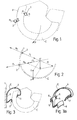
- Figure 1 represents a diagrammatic view of the stresses acting on the suspension of the helmet -C-.
- -P- diagrammatically represents the weight of the helmet -C-, which breaks down into two stresses -P 1 - and -P 2 -, which are applied, respectively, at the said points 1 and 2.
- respective reaction stresses -R 1 - and -R 2 - appear, equal to and opposing the aforesaid -P 1 - and -P 2 - stresses.
- Figure 2 shows a static diagram of the said stresses of the suspension system as per the invention.
- the weight -P- of the helmet -C- applied at the centre of gravity -G- of the helmet breaks down at point -G'- where the stresses meet, in the two parts -P 1 - and-P 2 -, which are applied, respectively, at points 1 and 2.
- the two aforesaid stresses -R 1 - and -R 2 - equal and opposing, appear by the principle of action and reaction, and these reestablish the balance of the system of stresses, according to the invention.
- the helmet -C- is supported on the outside at the lower point 2, and on the inside it is supported at the top point 1.
- the two support points 1 and 2 are connected to each other by a component -E-, which is attached to a fixture -S-, such as a wall or similar, by a third point 3.
- this component -E- is basically C-shaped, and its ends define the two support points (see figures 3 to 6).
- the aforesaid third point 3 for attachment of the component -E- to the fixture -S- is located between the two support points 1 and 2, as is shown in figures 3 to 5.
- this third point 3 can be provided with an extension of one of the branches of the C-shape of the component -E-, as is shown in figure 6.
- the extension is of the branch adjacent to the fixture -S-, it could likewise be of the other branch, away from this fixture.
- This invention provides that the component -E-should be in one single piece, as is shown in the figures, or of several pieces, whether or not these are joined to each other.
- component -E- shown in figure 3a consists of a strip 4 bent in a C-shape, which, in the middle, has two sideways extensions 5, provided with respective holes 6, which forms the said third point 3, for attachment to the fixture -S-. At the ends, it defines two curved plaques 7 and 8, which form the support points 1 and 2 respectively, replacing the points with small surfaces, which improve the support and prolong the life of the helmet -C-.
- the component -E- shown in figure 4a consists of two parallel branches 9, connected in the middle by a coupling 10 with a cover, provided with two holes 11, which forms the said third point 3, to attach the component -E- to the fixture -S-.
- a coupling 10 with a cover, provided with two holes 11, which forms the said third point 3, to attach the component -E- to the fixture -S-.
- the component -E- shown in figure 5a consists of a component 14, the top end of which defines a rounded shape 15, which forms support point 1, and the opposite, lower end of which, has a plaque 16 which rocks vertically, which forms support point 2. In the middle, lower down, it has a crosswise recess 17 with an intermediate thickening 18 below, which forms the said third point 3, and enables it to be connected by sliding into a means 19 shaped accordingly, which is attached lengthways to the fixture -S-.
- This component 14 has serrating 20 at the top, which helps any outer garment hung individually, or with the helmet -C-, to be hung up and held fast on this component 14.
- the component -E- shown in figure 6 consists of a component 21, which, by one of the branches of the -C-, specifically by the branch corresponding to support point 2, is extended by a tab 22, double-elbowed, and at its end which forms the said third point 3, it is attached to the fixture -S-.
- the invention provides that the extension can be along the other branch, corresponding to support point 1, which would be bent at the top and would fulfil the same function.
- component -E- may be any as suitable, as may the materials of which it is made wholly or in part, as it may be in one single material or several, and may be metal, metal with plastic and rubber, plastic, etc., as appropriate.
Landscapes
- Helmets And Other Head Coverings (AREA)
- Axle Suspensions And Sidecars For Cycles (AREA)
- Transition And Organic Metals Composition Catalysts For Addition Polymerization (AREA)
- Addition Polymer Or Copolymer, Post-Treatments, Or Chemical Modifications (AREA)
- Organic Low-Molecular-Weight Compounds And Preparation Thereof (AREA)
Abstract

Description
- The invention is concerned with a suspension system especially for motorcycle helmets.
- As is well known, motorcycle helmets are very troublesome for their users, as they are normally carried in one hand in order not to leave them on the motorcycle and to prevent them from being stolen.
- Users normally come up against the problem that their are no ideal places or fittings for them to leave or hang up the helmets safely and, if they are left on a table or similar, they tend to roll and run a great risk of falling on the floor and being damaged.
- This invention eliminates these problems and provides a suspension system, applicable very simply to places frequented by motorcycle riders, or simply in workplaces or equivalent of people who habitually use motorcycles and who normally take the helmet with them, whereby the helmet does not cause them the inconvenience of having to take it with them, since, when they reach their work or habitual place, they can hang it up completely safely in terms of the helmet's integrity, without it producing any hindrance to their work or activity.
- The suspension system especially for motorcycle helmets with which this invention is concerned comprises two support points, inside and outside at the back of the helmet, located at different heights.
- The helmet is supported on the outside at the lower point and on the inside at the top point.
- According to the invention, both points are connected to each other by at least one component which is attached to a fixture by a third point.
- This component is basically C-shaped, and its ends define the two support points.
- According to the invention, the third point can be located between the two support points or in an extension of one of the branches of the component.
- These and other features will be made clearer from the detailed description which follows, to assist which two sheets of drawings are attached, showing a practical case of embodiment, which is cited solely as an example, and is not limitative of the scope of this invention.
- In the drawings:
- Figure 1 is an elevational diagrammatic view showing the helmet and the suspension system as per the invention,
- figure 2 is a view showing a diagram of stresses of the suspension system,
- figures 3, 4 and 5 show an elevational view of an embodiment of the system as per the invention. Figures 3a, 4a and 5a show a perspective view of specific embodiments.
- Figure 6 shows an elevational view of another embodiment of the system as per the invention.
- According to the drawings, the suspension system especially for motorcycle helmets with which this invention is concerned comprises two
support points support points - Figure 1 represents a diagrammatic view of the stresses acting on the suspension of the helmet -C-. -P- diagrammatically represents the weight of the helmet -C-, which breaks down into two stresses -P1- and -P2-, which are applied, respectively, at the
said points - Figure 2 shows a static diagram of the said stresses of the suspension system as per the invention. As can be seen, the weight -P- of the helmet -C- applied at the centre of gravity -G- of the helmet breaks down at point -G'- where the stresses meet, in the two parts -P1- and-P2-, which are applied, respectively, at
points - As can be seen in the figures, the helmet -C- is supported on the outside at the
lower point 2, and on the inside it is supported at thetop point 1. - According to the invention, the two
support points - As can be seen, this component -E- is basically C-shaped, and its ends define the two support points (see figures 3 to 6).
- According to the invention, the aforesaid third point 3 for attachment of the component -E- to the fixture -S- is located between the two
support points - This invention provides that the component -E-should be in one single piece, as is shown in the figures, or of several pieces, whether or not these are joined to each other.
- As is shown in the figures, there are different elements of components -E- which are essentially the same, in that they fulfil the purpose of the suspension system of the invention.
- Thus, component -E- shown in figure 3a consists of a strip 4 bent in a C-shape, which, in the middle, has two
sideways extensions 5, provided withrespective holes 6, which forms the said third point 3, for attachment to the fixture -S-. At the ends, it defines two curved plaques 7 and 8, which form thesupport points - The component -E- shown in figure 4a consists of two
parallel branches 9, connected in the middle by acoupling 10 with a cover, provided with twoholes 11, which forms the said third point 3, to attach the component -E- to the fixture -S-. At the joined ends of thesebranches 9, there are directional rubbers orpads support points - The component -E- shown in figure 5a consists of a
component 14, the top end of which defines arounded shape 15, which formssupport point 1, and the opposite, lower end of which, has aplaque 16 which rocks vertically, which formssupport point 2. In the middle, lower down, it has acrosswise recess 17 with anintermediate thickening 18 below, which forms the said third point 3, and enables it to be connected by sliding into ameans 19 shaped accordingly, which is attached lengthways to the fixture -S-. Thiscomponent 14 has serrating 20 at the top, which helps any outer garment hung individually, or with the helmet -C-, to be hung up and held fast on thiscomponent 14. - The component -E- shown in figure 6 consists of a
component 21, which, by one of the branches of the -C-, specifically by the branch corresponding tosupport point 2, is extended by atab 22, double-elbowed, and at its end which forms the said third point 3, it is attached to the fixture -S-. The invention provides that the extension can be along the other branch, corresponding tosupport point 1, which would be bent at the top and would fulfil the same function. - According to this invention, the embodiments of component -E- may be any as suitable, as may the materials of which it is made wholly or in part, as it may be in one single material or several, and may be metal, metal with plastic and rubber, plastic, etc., as appropriate.
Claims (6)
- Suspension system especially for motorcycle helmets, characterized by the fact that it comprises two support points (1,2) on the inside and outside of the back (p) of the helmet (C), located at different heights.
- Suspension system, according to claim 1, characterized by the fact that the helmet (C) is supported on the outside at the lower point (2) and on the inside by the top point (1).
- Suspension system, according to claims 1 and 2, characterized by the fact that these support points (1,2) are connected to each other by at least one component (E) which is attached to a fixture (S) by a third point (3).
- Suspension system, according to the preceding claims, characterized by the fact that this component (E) is basically C-shaped, and its ends define the two support point (1,2).
- Suspension system, according to claim 4, characterized by the fact that this third point (3) for attachment of the component (E) to a fixture (S) is located between the two support points (1,2).
- Suspension system, according to claim 4, characterized by the fact that the third point (3) for attachment of the component (E) to a fixture (S) is provided with an extension (22) of one of the branches of the component (E).
Applications Claiming Priority (2)
| Application Number | Priority Date | Filing Date | Title |
|---|---|---|---|
| ES9600950 | 1996-04-26 | ||
| ES009600950A ES2170592B1 (en) | 1996-04-26 | 1996-04-26 | SUSPENSION SYSTEM SPECIALLY HELMETS FOR MOTORCYCLES. |
Publications (3)
| Publication Number | Publication Date |
|---|---|
| EP0803216A2 true EP0803216A2 (en) | 1997-10-29 |
| EP0803216A3 EP0803216A3 (en) | 1999-05-06 |
| EP0803216B1 EP0803216B1 (en) | 2004-08-04 |
Family
ID=8294630
Family Applications (1)
| Application Number | Title | Priority Date | Filing Date |
|---|---|---|---|
| EP97500071A Expired - Lifetime EP0803216B1 (en) | 1996-04-26 | 1997-04-21 | Suspension system in combination with a motorcycle helmet |
Country Status (6)
| Country | Link |
|---|---|
| US (1) | US5927515A (en) |
| EP (1) | EP0803216B1 (en) |
| AT (1) | ATE272346T1 (en) |
| AU (1) | AU724702B2 (en) |
| DE (1) | DE69730074D1 (en) |
| ES (2) | ES2170592B1 (en) |
Cited By (3)
| Publication number | Priority date | Publication date | Assignee | Title |
|---|---|---|---|---|
| JP2010215126A (en) * | 2009-03-17 | 2010-09-30 | Toshiro Yoshimizu | Baggage holding device |
| GB2480653A (en) * | 2010-05-26 | 2011-11-30 | Austen Faulkner | Collapsible Helmet Stand |
| GB2503525A (en) * | 2012-06-30 | 2014-01-01 | Timothy Lionel David Mccrea | Bicycle or wall-mounted helmet holder |
Families Citing this family (4)
| Publication number | Priority date | Publication date | Assignee | Title |
|---|---|---|---|---|
| US8770396B2 (en) | 2010-08-20 | 2014-07-08 | Eric K. Salys | Storage and drying device for helmets and accessories (visor, gloves, shoulder pads, neck brace, knee pads, keys, etc.) |
| US10717317B2 (en) * | 2015-09-18 | 2020-07-21 | John Nobi | Animal skull mount clip system and method of use |
| US11871859B1 (en) * | 2021-10-20 | 2024-01-16 | Everett Scott Morrison | Hat display |
| USD1002204S1 (en) * | 2021-11-10 | 2023-10-24 | Modern JP Brands LLC | Hat holder |
Family Cites Families (19)
| Publication number | Priority date | Publication date | Assignee | Title |
|---|---|---|---|---|
| US2711873A (en) * | 1955-06-28 | Can holder | ||
| US1203942A (en) * | 1916-06-13 | 1916-11-07 | James Oldham Walker | Sap-cup holder. |
| US1449698A (en) * | 1922-02-27 | 1923-03-27 | Raymond W Roragen | Kitchen-utensil rack |
| US1478209A (en) * | 1923-02-28 | 1923-12-18 | Albert E Eaton | Utensil hanger |
| US2524396A (en) * | 1946-05-16 | 1950-10-03 | Papalexis James | Garment holder |
| US3104013A (en) * | 1961-06-02 | 1963-09-17 | Hal M Fisk | Shoe display devices |
| BR7605106A (en) * | 1975-08-06 | 1977-08-02 | Motobecane Ateliers | DEVICE AGAINST THEFT FOR HELMET ADAPTED TO THIS DEVICE |
| FR2385578A1 (en) * | 1977-03-30 | 1978-10-27 | Perrot Francois | HELMET LOCK |
| US4078755A (en) * | 1977-05-02 | 1978-03-14 | John Grover Erickson | Clip type hanger for aperture boards |
| AU4591379A (en) * | 1978-04-17 | 1979-10-25 | John Todd | Helmet locking device |
| US4245807A (en) * | 1979-02-09 | 1981-01-20 | Daniel York | Bucket bracket |
| US4438877A (en) * | 1983-06-13 | 1984-03-27 | Jackson William S | Helmet restraining device |
| JPH0139496Y2 (en) * | 1985-07-04 | 1989-11-27 | ||
| IT206604Z2 (en) * | 1986-06-04 | 1987-08-10 | Piaggio & C Spa | TWO-WHEEL VEHICLE WITH LOCKING DEVICE OF AN OBJECT IN GENERAL, AND IN PARTICULAR OF A PROTECTION HELMET, TO THE STRUCTURE OF THE VEHICLE ITSELF. |
| US4863216A (en) * | 1988-11-01 | 1989-09-05 | Prescott Clovis H | Baby chair of the type which hooks on a table edge |
| US5038941A (en) * | 1990-03-09 | 1991-08-13 | Jac Bastiaansen | Hat rack |
| US5137157A (en) * | 1990-08-16 | 1992-08-11 | Lawson James D | Cap holder |
| US5246195A (en) * | 1992-03-02 | 1993-09-21 | Huff Daniel C | Lid holder |
| US5480073A (en) * | 1994-07-05 | 1996-01-02 | Lamanna; Frank A. | Cap holder apparatus |
-
1996
- 1996-04-26 ES ES009600950A patent/ES2170592B1/en not_active Expired - Fee Related
-
1997
- 1997-04-18 AU AU18963/97A patent/AU724702B2/en not_active Ceased
- 1997-04-21 AT AT97500071T patent/ATE272346T1/en not_active IP Right Cessation
- 1997-04-21 ES ES97500071T patent/ES2225944T3/en not_active Expired - Lifetime
- 1997-04-21 EP EP97500071A patent/EP0803216B1/en not_active Expired - Lifetime
- 1997-04-21 DE DE69730074T patent/DE69730074D1/en not_active Expired - Lifetime
- 1997-04-23 US US08/838,946 patent/US5927515A/en not_active Expired - Fee Related
Cited By (3)
| Publication number | Priority date | Publication date | Assignee | Title |
|---|---|---|---|---|
| JP2010215126A (en) * | 2009-03-17 | 2010-09-30 | Toshiro Yoshimizu | Baggage holding device |
| GB2480653A (en) * | 2010-05-26 | 2011-11-30 | Austen Faulkner | Collapsible Helmet Stand |
| GB2503525A (en) * | 2012-06-30 | 2014-01-01 | Timothy Lionel David Mccrea | Bicycle or wall-mounted helmet holder |
Also Published As
| Publication number | Publication date |
|---|---|
| ES2225944T3 (en) | 2005-03-16 |
| AU1896397A (en) | 1997-10-30 |
| ES2170592A1 (en) | 2002-08-01 |
| AU724702B2 (en) | 2000-09-28 |
| EP0803216B1 (en) | 2004-08-04 |
| EP0803216A3 (en) | 1999-05-06 |
| DE69730074D1 (en) | 2004-09-09 |
| US5927515A (en) | 1999-07-27 |
| ATE272346T1 (en) | 2004-08-15 |
| ES2170592B1 (en) | 2003-12-01 |
Similar Documents
| Publication | Publication Date | Title |
|---|---|---|
| USD390493S (en) | Money clip | |
| US6561364B1 (en) | Portable shelf for mounting on a towel bar | |
| EP0925998A3 (en) | Seatback carrier | |
| EP0931487A3 (en) | Baby carrier | |
| ES2117360T3 (en) | MOTORCYCLE WINDSHIELD. | |
| EP1132512A4 (en) | NON WOVEN WITH HANGING FUNCTION | |
| US5927515A (en) | Suspension system especially for motorcycle helmets | |
| US6135473A (en) | Removable mounting plate for sissy bar | |
| USD367595S (en) | Suspension attachment for a clearing saw | |
| USD452335S1 (en) | Steel guard rail post safety delineator-pedestrian | |
| US3635381A (en) | Front floor mounted and seat attached vehicle gun rack | |
| KR101316114B1 (en) | A chair | |
| US5377390A (en) | Adjustable tie chain | |
| USD481556S1 (en) | Article suspension stand | |
| JPH0641498Y2 (en) | Trouser hanger | |
| US6988587B1 (en) | Fire escape device | |
| CN223529246U (en) | Lengthening assembly for changing small clothes hanger into large clothes hanger | |
| USD455706S1 (en) | Carrier for use on a bicycle | |
| CA2211311C (en) | Clothes hanger | |
| JP3025515U (en) | Umbrella holder | |
| USD422536S (en) | End-mounted safety bar for handlebars | |
| USD414786S (en) | Table for a table saw | |
| EP0870454A3 (en) | A hanger | |
| JPS5940933Y2 (en) | hanger | |
| CA2604296A1 (en) | Serviette support |
Legal Events
| Date | Code | Title | Description |
|---|---|---|---|
| PUAI | Public reference made under article 153(3) epc to a published international application that has entered the european phase |
Free format text: ORIGINAL CODE: 0009012 |
|
| AK | Designated contracting states |
Kind code of ref document: A2 Designated state(s): AT BE CH DE DK ES FI FR GB GR IE IT LI LU MC NL PT SE |
|
| PUAL | Search report despatched |
Free format text: ORIGINAL CODE: 0009013 |
|
| AK | Designated contracting states |
Kind code of ref document: A3 Designated state(s): AT BE CH DE DK ES FI FR GB GR IE IT LI LU MC NL PT SE |
|
| 17P | Request for examination filed |
Effective date: 19990526 |
|
| D17P | Request for examination filed (deleted) | ||
| R17P | Request for examination filed (corrected) |
Effective date: 19991027 |
|
| 17Q | First examination report despatched |
Effective date: 20010705 |
|
| GRAP | Despatch of communication of intention to grant a patent |
Free format text: ORIGINAL CODE: EPIDOSNIGR1 |
|
| RTI1 | Title (correction) |
Free format text: SUSPENSION SYSTEM IN COMBINATION WITH A MOTORCYCLE HELMET |
|
| GRAS | Grant fee paid |
Free format text: ORIGINAL CODE: EPIDOSNIGR3 |
|
| GRAA | (expected) grant |
Free format text: ORIGINAL CODE: 0009210 |
|
| AK | Designated contracting states |
Kind code of ref document: B1 Designated state(s): AT BE CH DE DK ES FI FR GB GR IE IT LI LU MC NL PT SE |
|
| PG25 | Lapsed in a contracting state [announced via postgrant information from national office to epo] |
Ref country code: NL Free format text: LAPSE BECAUSE OF FAILURE TO SUBMIT A TRANSLATION OF THE DESCRIPTION OR TO PAY THE FEE WITHIN THE PRESCRIBED TIME-LIMIT Effective date: 20040804 Ref country code: LI Free format text: LAPSE BECAUSE OF FAILURE TO SUBMIT A TRANSLATION OF THE DESCRIPTION OR TO PAY THE FEE WITHIN THE PRESCRIBED TIME-LIMIT Effective date: 20040804 Ref country code: IT Free format text: LAPSE BECAUSE OF FAILURE TO SUBMIT A TRANSLATION OF THE DESCRIPTION OR TO PAY THE FEE WITHIN THE PRE;WARNING: LAPSES OF ITALIAN PATENTS WITH EFFECTIVE DATE BEFORE 2007 MAY HAVE OCCURRED AT ANY TIME BEFORE 2007. THE CORRECT EFFECTIVE DATE MAY BE DIFFERENT FROM THE ONE RECORDED.SCRIBED TIME-LIMIT Effective date: 20040804 Ref country code: FR Free format text: LAPSE BECAUSE OF FAILURE TO SUBMIT A TRANSLATION OF THE DESCRIPTION OR TO PAY THE FEE WITHIN THE PRESCRIBED TIME-LIMIT Effective date: 20040804 Ref country code: FI Free format text: LAPSE BECAUSE OF FAILURE TO SUBMIT A TRANSLATION OF THE DESCRIPTION OR TO PAY THE FEE WITHIN THE PRESCRIBED TIME-LIMIT Effective date: 20040804 Ref country code: CH Free format text: LAPSE BECAUSE OF FAILURE TO SUBMIT A TRANSLATION OF THE DESCRIPTION OR TO PAY THE FEE WITHIN THE PRESCRIBED TIME-LIMIT Effective date: 20040804 Ref country code: BE Free format text: LAPSE BECAUSE OF FAILURE TO SUBMIT A TRANSLATION OF THE DESCRIPTION OR TO PAY THE FEE WITHIN THE PRESCRIBED TIME-LIMIT Effective date: 20040804 Ref country code: AT Free format text: LAPSE BECAUSE OF FAILURE TO SUBMIT A TRANSLATION OF THE DESCRIPTION OR TO PAY THE FEE WITHIN THE PRESCRIBED TIME-LIMIT Effective date: 20040804 |
|
| REG | Reference to a national code |
Ref country code: GB Ref legal event code: FG4D |
|
| REG | Reference to a national code |
Ref country code: CH Ref legal event code: EP |
|
| REG | Reference to a national code |
Ref country code: IE Ref legal event code: FG4D |
|
| REF | Corresponds to: |
Ref document number: 69730074 Country of ref document: DE Date of ref document: 20040909 Kind code of ref document: P |
|
| PG25 | Lapsed in a contracting state [announced via postgrant information from national office to epo] |
Ref country code: SE Free format text: LAPSE BECAUSE OF FAILURE TO SUBMIT A TRANSLATION OF THE DESCRIPTION OR TO PAY THE FEE WITHIN THE PRESCRIBED TIME-LIMIT Effective date: 20041104 Ref country code: GR Free format text: LAPSE BECAUSE OF FAILURE TO SUBMIT A TRANSLATION OF THE DESCRIPTION OR TO PAY THE FEE WITHIN THE PRESCRIBED TIME-LIMIT Effective date: 20041104 Ref country code: DK Free format text: LAPSE BECAUSE OF FAILURE TO SUBMIT A TRANSLATION OF THE DESCRIPTION OR TO PAY THE FEE WITHIN THE PRESCRIBED TIME-LIMIT Effective date: 20041104 |
|
| PG25 | Lapsed in a contracting state [announced via postgrant information from national office to epo] |
Ref country code: DE Free format text: LAPSE BECAUSE OF FAILURE TO SUBMIT A TRANSLATION OF THE DESCRIPTION OR TO PAY THE FEE WITHIN THE PRESCRIBED TIME-LIMIT Effective date: 20041105 |
|
| NLV1 | Nl: lapsed or annulled due to failure to fulfill the requirements of art. 29p and 29m of the patents act | ||
| REG | Reference to a national code |
Ref country code: CH Ref legal event code: PL |
|
| REG | Reference to a national code |
Ref country code: ES Ref legal event code: FG2A Ref document number: 2225944 Country of ref document: ES Kind code of ref document: T3 |
|
| PG25 | Lapsed in a contracting state [announced via postgrant information from national office to epo] |
Ref country code: LU Free format text: LAPSE BECAUSE OF NON-PAYMENT OF DUE FEES Effective date: 20050421 Ref country code: IE Free format text: LAPSE BECAUSE OF NON-PAYMENT OF DUE FEES Effective date: 20050421 Ref country code: GB Free format text: LAPSE BECAUSE OF NON-PAYMENT OF DUE FEES Effective date: 20050421 |
|
| PG25 | Lapsed in a contracting state [announced via postgrant information from national office to epo] |
Ref country code: MC Free format text: LAPSE BECAUSE OF NON-PAYMENT OF DUE FEES Effective date: 20050430 |
|
| PLBE | No opposition filed within time limit |
Free format text: ORIGINAL CODE: 0009261 |
|
| STAA | Information on the status of an ep patent application or granted ep patent |
Free format text: STATUS: NO OPPOSITION FILED WITHIN TIME LIMIT |
|
| 26N | No opposition filed |
Effective date: 20050506 |
|
| EN | Fr: translation not filed | ||
| GBPC | Gb: european patent ceased through non-payment of renewal fee |
Effective date: 20050421 |
|
| PG25 | Lapsed in a contracting state [announced via postgrant information from national office to epo] |
Ref country code: PT Free format text: LAPSE BECAUSE OF NON-PAYMENT OF DUE FEES Effective date: 20050104 |
|
| PGFP | Annual fee paid to national office [announced via postgrant information from national office to epo] |
Ref country code: ES Payment date: 20120424 Year of fee payment: 16 |
|
| REG | Reference to a national code |
Ref country code: ES Ref legal event code: FD2A Effective date: 20140610 |
|
| PG25 | Lapsed in a contracting state [announced via postgrant information from national office to epo] |
Ref country code: ES Free format text: LAPSE BECAUSE OF NON-PAYMENT OF DUE FEES Effective date: 20130422 |