EP0803182A2 - Mowing and conveying device for stalk cereals - Google Patents
Mowing and conveying device for stalk cereals Download PDFInfo
- Publication number
- EP0803182A2 EP0803182A2 EP97105865A EP97105865A EP0803182A2 EP 0803182 A2 EP0803182 A2 EP 0803182A2 EP 97105865 A EP97105865 A EP 97105865A EP 97105865 A EP97105865 A EP 97105865A EP 0803182 A2 EP0803182 A2 EP 0803182A2
- Authority
- EP
- European Patent Office
- Prior art keywords
- cutting
- conveying device
- conveyor
- conveying
- flank
- Prior art date
- Legal status (The legal status is an assumption and is not a legal conclusion. Google has not performed a legal analysis and makes no representation as to the accuracy of the status listed.)
- Granted
Links
Images
Classifications
-
- A—HUMAN NECESSITIES
- A01—AGRICULTURE; FORESTRY; ANIMAL HUSBANDRY; HUNTING; TRAPPING; FISHING
- A01D—HARVESTING; MOWING
- A01D43/00—Mowers combined with apparatus performing additional operations while mowing
- A01D43/08—Mowers combined with apparatus performing additional operations while mowing with means for cutting up the mown crop, e.g. forage harvesters
- A01D43/081—Mowers combined with apparatus performing additional operations while mowing with means for cutting up the mown crop, e.g. forage harvesters specially adapted for ensilage of maize
- A01D43/082—Gathering units
Definitions
- the invention relates to a cutting and conveying device for stalked stalk material, in particular for corn.
- European patent application 0099 527 a cutting and conveying device is described in particular for maize.
- the cut stalks are picked up in bulges between adjacent conveyor tines in the circumferential area of the conveyor disks and conveyed to a delivery point.
- there are stationary divider tips according to EP-A-0099 527 which are bridged by guide parts which run in the contour between the conveyor disks in the circumferential direction and hold the straws in the bulges.
- the object of the present invention is to further develop the cutting and conveying device such that the conveyor disks themselves reliably perform the holding and guiding function without guide parts.
- the measures specified in claim 1 are provided.
- the bulges By forming the bulges in at least one of the conveyor disks in such a way that there are at least two holding chambers, the bulges can reliably accommodate and transport the stems in chambers. Additional guide parts are not required.
- Two holding chambers are preferably formed, namely a front and a rear one, which is located radially further inwards. In this rear chamber, cut stems can be picked up at more distant places, while in the front chamber there is then space for stems cut later, so that at least two stems can be transported in each bulge.
- the holding chambers are formed on the bulges of the lower conveyor disk. It is particularly advantageous if the holding chambers are formed on the non-conveying flank.
- the non-conveying, leading flank of the bulge of the lower conveyor disc does not initially grasp the cut crop.
- the maize plant covered with corn cobs has a tendency during the cutting process to initially remain in its position due to the inertia.
- the formation of the chambers takes place most suitably by the appropriate design of the contour of the bulge by lugs which project against the direction of rotation on the lower conveyor disk and in the direction of rotation on the upper conveyor disk.
- the lugs divide the bulge approximately in the middle of its radial extension into two chambers.
- a stem lifter is placed in front of the rotor formed by the conveyor disks and the cutting disk, which is provided at the rear end with a position transmitter, which in the area of the contour of the stem lifter rearwards between the engages upper and lower conveyor. It is the task of this position transmitter to direct the stems gripped at previously cut places into the rear chamber.
- the position transmitter is provided with a flank that runs radially inward in the direction of rotation and has an inclination. This flank ends approximately at the height of the radial distance between the lugs of the lower conveyor disc, so that the stems that slide along the flank are then guided into the contour of the rear chamber and then "latch" there by themselves on the basis of the principle described above.
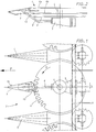
- FIG. 1 shows a top view of a cutting and conveying device with a plurality of conveying devices which are arranged next to one another transversely to the direction of travel F and are separated from one another by large stem dividers 1.
- Each device consists of a mowing and conveying rotor 2 with a stem lifter 3 in front of it.
- a cutting disk 5 and two conveyor disks namely an upper conveyor disk 6a and a lower conveyor disk 6b, are coaxially attached to one another at intervals on an approximately vertical rotor shaft 4.
- the drive takes place by means of a horizontal drive shaft via an angular gear, in the housing 7 of which the rotor shaft 4 is mounted.
- a support 8 which rises to the front and upward is attached, which supports the stem lifter 3.
- the two conveyor disks 6a, 6b rotate together in the direction of the arrow D shown and have bulges 9 on the edge, which are described in more detail below.
- the stem lifter 3 is formed from sheet metal. It has a point at the front and widens towards the back. With regard to the direction of rotation of the conveyor disks 6a, 6b, its side 3a is referred to as the feed side. At the rear end of this page is the position transmitter within the contour of stem lifter 3 10 in the direction of the space between the upper conveyor disk 6a and the lower conveyor disk 6b (see FIG. 2).
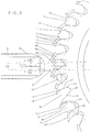
- Figure 3 shows the design of the conveyor disks and also the measurement in detail.
- the knife 5 is only indicated below two bulges in the upper area of FIG. 3 and has a toothed cutting edge 5a. For the sake of clarity, this border is not drawn under all bulges.
- top of the cutting disc 5 can be attached to the top at intervals, upright, not shown, but described in the German patent application 195 35 454 catch strips, which run at a flat angle to the tangent, the leading beginning of the catch strips radially further outside than the trailing end is.
- the cut stems are thereby acted upon radially inwards towards the rotor axis.
- FIG. 3 also clearly shows the shape of the bulges of the lower conveyor disk 6b and the upper conveyor disk 6a.
- Each conveyor disc has tines.
- the conveyor tines of the upper conveyor disc are provided with the reference symbol 11, those of the lower with the reference symbol 12.
- the respective pairs of tines of the upper and lower conveyor discs are offset from one another in the direction of rotation in such a way that the upper conveyor tine 11 leads by a small amount in relation to the lower conveyor tine .
- the conveyor tines 11, 12 each form an inlet surface on their end faces 13, the edge 14 trailing in the direction of rotation lying further inside than the respective leading tip of the adjacent subsequent conveyor tine of the same conveyor disk in each case.
- the contours of the bulge are different.
- the bulge 9a of the upper conveyor disk starting from the tip 16, runs inwards in two of the radial arches 18 and 19 which are somewhat lagging and separated by a nose 17. These partial arches 18 and 19 of the nose 17 form the supporting flank of the bulge 9a.
- the bulge extends from the rear partial arch 19 via a semicircular curvature 20 into the non-conveying flank 21 that is steeper than the radial.
- the bulge 9b of the lower conveyor disk merges from the tine tip 15 with its conveying flank 22, initially radially trailing, then arched radially leading backwards into the non-conveying flank 24.
- the non-conveying flank 24 is divided into a rear chamber 26 and a front chamber 27 by the nose 25.
- the position transmitter 10 of the feed side 3a runs radially with an inclination toward the direction of rotation inwards into the contour of the conveyor disks and ends with the positioning tip 28 approximately at the level of the lugs 17 and 25 separating the rear chamber. It lies essentially in the contour behind the stem lifter 3.
- the flank 29 of the position transmitter 10 facing the feed side 3a is at an angle of approximately 45 ° to the radial.
- the stems cut on the feed side are gripped by the conveyor tines 11 and 12 and taken away. Due to the above-mentioned persistence of the upper part of stalky stalks, especially with maize, a tipping moment arises after the cutting process, which tries to tilt the stalk around the contact point on the conveying flank of the upper conveyor disc against the direction of rotation, so that the below coming to the upper conveyor disc, the foot region of the stem coming into one of the chambers 26 or 27 of the lower recess 9b is pressed and remains there.
- the conveying flank grips the stem either in the front chamber section 18 or in the rear chamber section 19 of the bulge 9a of the upper conveyor disk.
- the division of the chamber by the noses fixes and holds the stalks in such a way that they are transported away without falling out and without additional guide elements.
- Stems, which are accommodated in the front chamber 27, are now conveyed in the course of further transport against the inclined flank 29 of the position transmitter 10 and slide along it radially inwards and are thus assigned to the radially inner chamber 26 and to that on the upper disc Sub-section 19 positioned and supported in particular by the nose 25 of the lower conveyor but also by the nose 17 in the upper conveyor radially outward, so that they can not fall out of the bulges due to centrifugal forces, rather reliably held and transported without additional guide parts will.
- Additional stems which are cut in the direction of rotation behind the stem lifter 3, can pass from the front region of the bulges through the chamber 27 and the associated partial arch section 18 in the upper conveyor disc and can also be reliably held and transported.
- a rotating scraper is preferably used, such as the one used e.g. is described in German patent application P 195 35 453.2.
Abstract
Description
Die Erfindung betrifft eine Schneid- und Fördervorrichtung für stengeliges Halmgut, insbesondere für Mais.The invention relates to a cutting and conveying device for stalked stalk material, in particular for corn.
In der europäischen Patentanmeldung 0099 527 ist eine Schneid- und Fördervorrichtung insbesondere für Mais beschrieben. Dort sind umlaufende Schneidscheiben und koaxiale Förderscheiben vorhanden, die teilweise gleichsinnig, teilweise gegensinnig, aber immer mit unterschiedlichen Umfangsgeschwindigkeiten rotieren. Die abgeschnittenen Halmgutstengel werden in Ausbuchtungen zwischen benachbarten Förderzinken im Umfangsbereich der Förderscheiben aufgenommen und bis zu einer Abgabestelle gefördert. Um die Halme während des Transportes in den Ausbuchtungen festzuhalten, sind nach der EP-A-0099 527 stationäre Teilerspitzen vorhanden, die durch Führungsteile überbrückt sind, die in der Kontur zwischen den Förderscheiben in Umfangsrichtung verlaufen und die Halme in den Ausbuchtungen halten. Da dadurch die Schnittbreite in viele einzelne Arbeitsbereiche unterteilt wird, geht zum einen Schnittraum verloren und zum anderen werden Stengel, die nicht gerade in den Schneidspalt zwischen den Abteilerspitzen einlaufen, abgedrückt und schräg abgeschnitten. Die Führungsteile behindern außerdem den Schnittvorgang selbst, besonders bei feinhalmigem Erntegut.In European patent application 0099 527 a cutting and conveying device is described in particular for maize. There are revolving cutting disks and coaxial conveyor disks, which rotate partly in the same direction, partly in the opposite direction, but always with different peripheral speeds. The cut stalks are picked up in bulges between adjacent conveyor tines in the circumferential area of the conveyor disks and conveyed to a delivery point. In order to hold the straws in the bulges during transport, there are stationary divider tips according to EP-A-0099 527, which are bridged by guide parts which run in the contour between the conveyor disks in the circumferential direction and hold the straws in the bulges. Since this divides the cutting width into many individual work areas, cutting space is lost on the one hand and stems that do not exactly enter the cutting gap between the compartment tips are pressed off and cut off at an angle. The guide parts also hinder the cutting process itself, especially with fine-stemmed crops.
In der nicht vorveröffentlichten deutschen Patentanmeldung 195 35 454 wird zur Vermeidung dieser Nachteile u.a. vorgeschlagen, die Ausbuchtungen mit einer bis zur Spitze der Förderzinken fortgesetzten Wölbung zu versehen, die den Halmgutstengel teilweise umschließt, so daß die Ausbuchtungen Haltefunktion ausüben können und im Arbeitsbreitenbereich keine Führungsteile mehr benötigt werden, weil die Ausbuchtungen selbst die Führung des Halmgutes übernehmen.In the unpublished German patent application 195 35 454 to avoid these disadvantages, it is proposed, inter alia, to provide the bulges with a curvature that continues up to the tip of the conveyor tines, which partially surrounds the stalk of stalk, so that the bulges can have a holding function and no guide parts in the working width range are needed because the bulges themselves take over the management of the crop.
Aufgabe der vorliegenden Erfindung ist es, die Schneid- und Fördervorrichtung so weiterzubilden, daß ohne Führungsteile die Förderscheiben selbst die Halte- und Führungsfunktion zuverlässig übernehmen.The object of the present invention is to further develop the cutting and conveying device such that the conveyor disks themselves reliably perform the holding and guiding function without guide parts.
Zur Lösung dieser Aufgabe sind die im Anspruch 1 angegebenen Maßnahmen vorgesehen. Durch die Ausbildung der Ausbuchtungen in wenigstens einer der Förderscheiben derart, daß sich mindestens zwei Haltekammern ergeben, können die Ausbuchtungen die Stengel zuverlässig in Kammern aufnehmen und transportieren. Zusätzliche Führungsteile werden nicht benötigt. Bevorzugt werden zwei Haltekammern ausgebildet, nämlich eine vordere und eine hintere, die radial weiter innen liegt. In dieser hinteren Kammer können an weiter entfernten Stellen geschnittene Stengel aufgenommen werden, während in der vorderen Kammer dann Platz für später geschnittene Stengel entsteht und so in jeder Ausbuchtung wenigstens zwei Stengel transportiert werden können.To achieve this object, the measures specified in
In vorteilhafter Ausgestaltung der Erfindung ist vorgesehen, die Haltekammern an den Ausbuchtungen der unterenFörderscheibe auszubilden. Insbesondere ist vorteilhaft, wenn dabei die Haltekammern an der nicht fördernden Flanke ausgebildet sind. Die nicht fördernde, vorlaufende Flanke der Ausbuchtung der unteren Förderscheibe ergreift an sich zunächst nicht das geschnittene Halmgut. Insbesondere beim Schneiden von Mais hat sich jedoch herausgestellt, daß die mit Maiskolben behangene Maispflanze insgesamt beim Schnittvorgang die Tendenz hat, zunächst in ihrer Position aufgrund der Trägheit zu verharren. Nachdem jedoch die Maispflanze am unteren Ende am Stengel von den Förderzinken ergriffen wird und daher der Fuß in Umfangsrichtung der Förderscheiben mitgerissen wird, der obere Teil der Pflanze jedoch nicht sofort mitgenommen wird, ergibt sich daraus ein Moment, das versucht, die Maispflanze an ihrem oberen Ende entgegen der Drehrichtung zu kippen. Dies führt dazu, daß nach dem Schnitt der Fuß der Pflanze aufgrund des Kippmomentes nach vorne ausweichen will und daher in Richtung der nichtfördernden Flanke der unteren Förderscheibe beaufschlagt wird, während er sich etwas oberhalb an der fördernden Flanke der oberen Förderscheibe quasi als Drehpunkt abstützt.In an advantageous embodiment of the invention, provision is made for the holding chambers to be formed on the bulges of the lower conveyor disk. It is particularly advantageous if the holding chambers are formed on the non-conveying flank. The non-conveying, leading flank of the bulge of the lower conveyor disc does not initially grasp the cut crop. However, in particular when cutting maize, it has been found that the maize plant covered with corn cobs has a tendency during the cutting process to initially remain in its position due to the inertia. However, after the maize plant is gripped by the conveyor tines at the lower end of the stem and therefore the foot is swept along in the circumferential direction of the conveyor disks, but the upper part of the plant is not immediately taken away, this results in a moment that tries to catch the maize plant on its upper one Tilt end against the direction of rotation. This leads to the fact that after cutting the foot of the plant due to the tilting moment wants to dodge at the front and is therefore acted upon in the direction of the non-conveying flank of the lower conveyor disk, while it is supported somewhat above the conveying flank of the upper conveyor disk as a fulcrum.
Wenn dann auch an der oberen Förderscheibe an der vorderen Flanke entsprechende Kammern ausgebildet sind, legt sich das geschnittene Halmgut in diese Kammern von selbst hinein und wird zuverlässig aufgenommen. Das Kippmoment der Pflanze entgegen der Drehrichtung sorgt für eine Fixierung, so daß ohne irgendwelche weiteren Führungsteile dann der Weitertransport erfolgen kann.If corresponding chambers are then also formed on the upper conveyor disc on the front flank, the cut stalk material automatically settles into these chambers and is reliably picked up. The tilting moment of the plant against the direction of rotation ensures fixation, so that further transport can then take place without any further guide parts.
Die Ausbildung der Kammern erfolgt am geeignetsten durch die entsprechende Gestaltung der Kontur der Ausbuchtung durch Nasen, die an der unteren Förderscheibe entgegen der Drehrichtung und an der oberen Förderscheibe in Drehrichtung vorspringen. Die Nasen unterteilen die Ausbuchtung etwa in der Mitte ihrer radialen Erstreckung somit in zwei Kammern.The formation of the chambers takes place most suitably by the appropriate design of the contour of the bulge by lugs which project against the direction of rotation on the lower conveyor disk and in the direction of rotation on the upper conveyor disk. The lugs divide the bulge approximately in the middle of its radial extension into two chambers.
In weiterer Ausgestaltung der Erfindung ist vorgesehen, daß etwa in der Mitte der Arbeitsbreite dem von den Förderscheiben und der Schneidscheibe gebildeten Rotor ein Stengelheber vorgesetzt ist, der am hinteren Ende mit einem Positionsgeber versehen ist, der im Bereich der Kontur des Stengelhebers nach hinten zwischen die obere und die untere Förderscheibe eingreift. Aufgabe dieses Positionsgebers ist es, die an zuvor geschnittenen Stellen ergriffenen Stengel in die hintere Kammer einzuweisen. Hierzu ist der Positionsgeber in vorteilhafter Ausgestaltung mit einer in Drehrichtung radial nach innen mit Neigung umlaufenden Flanke versehen. Diese Flanke endet etwa auf der Höhe des Radialabstandes der Nasen der unteren Förderscheibe, so daß die Stengel, die an der Flanke entlanggleiten, dann in die Kontur der hinteren Kammer geführt werden und dort dann aufgrund des oben beschriebenen Prinzips von selbst "verrasten".In a further embodiment of the invention it is provided that in the middle of the working width, a stem lifter is placed in front of the rotor formed by the conveyor disks and the cutting disk, which is provided at the rear end with a position transmitter, which in the area of the contour of the stem lifter rearwards between the engages upper and lower conveyor. It is the task of this position transmitter to direct the stems gripped at previously cut places into the rear chamber. For this purpose, in an advantageous embodiment, the position transmitter is provided with a flank that runs radially inward in the direction of rotation and has an inclination. This flank ends approximately at the height of the radial distance between the lugs of the lower conveyor disc, so that the stems that slide along the flank are then guided into the contour of the rear chamber and then "latch" there by themselves on the basis of the principle described above.
Die Erfindung wird im folgenden anhand des in der Zeichnung dargestellten Ausführungsbeispiels weiter erläutert und beschrieben. Dabei zeigt:
Figur 1- die Draufsicht auf eine erfindungsgemäße Schneid- und Fördervorrichtung,
Figur 2- eine schematische Seitenansicht der Vorrichtung nach
Figur 1, wobei weitere Antriebsteile weggelassen sind, Figur 3- eine Draufsicht auf einen Teil der Schneid- und Fördervorrichtung in gegenüber der
Figur 1 vergrößerter Darstellung.
- Figure 1
- the top view of a cutting and conveying device according to the invention,
- Figure 2
- 2 shows a schematic side view of the device according to FIG. 1, with further drive parts being omitted,
- Figure 3
- a plan view of part of the cutting and conveying device in an enlarged view compared to Figure 1.
Figur 1 zeigt eine Draufsicht einer Schneid- und Fördervorrichtung mit mehreren quer zur Fahrtrichtung F nebeneinander angeordneten Fördervorrichtungen, die durch große Stengelteiler 1 voneinander getrennt sind. Jede Vorrichtung besteht aus einem Mäh- und Förderrotor 2, dem ein Stengelheber 3 mittig vorgesetzt ist. Wie insbesondere Figur 2 zeigt, ist an einer etwa senkrechten Rotorwelle 4 eine Schneidscheibe 5 und zwei Förderscheiben, nämlich eine obere Förderscheibe 6a und eine untere Förderscheibe 6b in Abständen übereinander koaxial befestigt. Der Antrieb erfolgt mittels einer horizontalen Antriebswelle über ein Winkelgetriebe, in dessen Gehäuse 7 die Rotorwelle 4 gelagert ist. An dem Winkelgetriebegehäuse ist eine nach vorn und oben ansteigende Stütze 8 befestigt, welche den Stengelheber 3 trägt. Die beiden Förderscheiben 6a, 6b drehen sich gemeinsam in Richtung des gezeigten Pfeiles D und haben am Rand Ausbuchtungen 9, die weiter unten noch näher beschrieben werden. Der Stengelheber 3 ist aus Blech geformt. Er hat vorne eine Spitze und verbreitert sich nach hinten. Mit Bezug auf die Drehrichtung der Förderscheiben 6a, 6b wird seine Seite 3a als Zuförderseite bezeichnet. Am rückwärtigen Ende dieser Seite steht innerhalb der Kontur des Stengelhebers 3 der Positionsgeber 10 in Richtung auf den Zwischenraum zwischen der oberen Förderscheibe 6a und der unteren Förderscheibe 6b (vgl. Figur 2) ab.FIG. 1 shows a top view of a cutting and conveying device with a plurality of conveying devices which are arranged next to one another transversely to the direction of travel F and are separated from one another by
Figur 3 läßt die Ausbildung der Förderscheiben und auch des Messen im Detail erkennen. Das Messer 5 ist lediglich unterhalb zweier Ausbuchtungen im oberen Bereich der Figur 3 angedeutet und weist einen gezahnten Schneidrand 5a auf. Der Übersichtlichkeit halber ist dieser Rand nicht durchgehend unter allen Ausbuchtungen gezeichnet.Figure 3 shows the design of the conveyor disks and also the measurement in detail. The
Am Umfang der Schneidscheibe 5 können an deren Oberseite in Abständen hochkant stehende, nicht näher gezeigte, jedoch in der deutschen Patentanmeldung 195 35 454 beschriebene Fangstreifen befestigt sein, die in einem flachen Winkel zur Tangente verlaufen, wobei der vorauslaufende Anfang der Fangstreifen radial weiter außen als das nachlaufende Ende liegt. Die abgeschnittenen Stengel werden dadurch radial nach innen zur Rotorachse hin beaufschlagt.On the top of the
Die Figur 3 läßt des weiteren die Form der Ausbuchtungen der unteren Förderscheibe 6b und der oberen Förderscheibe 6a deutlich erkennen.FIG. 3 also clearly shows the shape of the bulges of the
Jede Förderscheibe hat Förderzinken. Die Förderzinken der oberen Förderscheibe sind mit dem Bezugszeichen 11 versehen, diejenigen der unteren mit dem Bezugszeichen 12. Die jeweiligen Zinkenpaare der oberen und unteren Förderscheibe sind in Drehrichtung derart zueinander versetzt, daß der obere Förderzinken 11 gegenüber dem unteren Förderzinken 12 um ein geringes Maß vorläuft. Die Förderzinken 11, 12 bilden auf ihren Stirnseiten 13 jeweils eine Einlauffläche, wobei die in Drehrichtung nachlaufende Kante 14 weiter innen liegt als die jeweilige vorauslaufende Spitze des benachbarten nachfolgenden Förderzinkens der jeweils selben Förderscheibe.Each conveyor disc has tines. The conveyor tines of the upper conveyor disc are provided with the
Die Konturen der Ausbuchtung sind, wie man erkennt, unterschiedlich. Im unteren Teilbereich der Figur 3 ist nebeneinanderliegend einmal nur die obere Ausbuchtung 9a und danebenliegend nur die untere Ausbuchtung 9b dargestellt, um klarer den Verlauf erläutern zu können. Wie man erkennt, verläuft die Ausbuchtung 9a der oberen Förderscheibe beginnend von der Spitze 16 weg in zwei der radialen etwas nacheilenden, durch eine Nase 17 getrennten Teilbögen 18 und 19 nach innen. Diese Teilbogen 18 und 19 der Nase 17 bilden die fördernde Flanke der Ausbuchtung 9a. Von dem hinteren Teilbogen 19 verläuft die Ausbuchtung über eine halbkreisförmige Krümmung 20 in die noch steiler zur Radialen angestellte nichtfördernde Flanke 21.As you can see, the contours of the bulge are different. In the lower part of FIG. 3, only the upper bulge 9a and next to it only the
Die Ausbuchtung 9b der unteren Förderscheibe dagegen geht von der Zinkenspitze 15 aus mit ihrer fördernden Flanke 22 zunächst radial nachlaufend, dann radial vorauseilend gewölbt nach hinten in die nichtfördernde Flanke 24 über. Die nichtfördernde Flanke 24 ist durch die Nase 25 in eine hintere Kammer 26 und eine vordere Kammer 27 abgeteilt.The
Die so erzeugten unterschiedlichen Formen der Ausbuchtungen überdecken sich in der dargestellten Weise. Soweit die Relativlage und die Ausbildung der Krümmungsverläufe nicht durch Maßzahlen, Krümmungsradien und Winkelangaben erläutert sind, können solche Verhältnisse der Zeichnung entnommen werden, die diesbezüglich maßstäblich dargestellt ist.The different forms of bulges created in this way overlap in the manner shown. Insofar as the relative position and the formation of the curvature curves are not explained by dimensions, radii of curvature and angle information, such relationships can be seen in the drawing, which is shown to scale in this regard.
Wie die Figur 3 ebenfalls erkennen läßt, verläuft der Positionsgeber 10 der Zuförderseite 3a radial mit Neigung zur Drehrichtung hin nach innen bis in die Kontur der Förderscheiben hinein und endet mit der Positionierspitze 28 etwa auf Höhe der die hintere Kammer trennenden Nasen 17 bzw. 25. Er liegt dabei im wesentlichen in der Kontur hinter dem Stengelheber 3. Die der Zuförderseite 3a zuweisende Flanke 29 des Positionsgebers 10 steht in einem Winkel von ca. 45° zur Radialen.As can also be seen in FIG. 3, the
Mit der so ausgebildeten Schneid- und Fördereinrichtung kann nun wie folgt gearbeitet werden:The cutting and conveying device designed in this way can now be used as follows:
Die auf der Zuförderseite geschnittenen Stengel werden von den Förderzinken 11 und 12 erfaßt und mitgenommen. Aufgrund des bereits oben erläuterten Verharrungsbestrebens des oberen Teils von stengeligem Halmgut, insbesondere bei Mais, entsteht ein Kippmoment nach dem Schneidvorgang, das versucht, den Stengel um den Anlagepunkt an der fördernden Flanke der oberen Förderscheibe entgegen der Drehrichtung zu kippen, so daß der unterhalb der oberen Förderscheibe zu liegen kommende Fußbereich des Stengels nach vorne in eine der Kammern 26 oder 27 der unteren Ausnehmung 9b gedrückt wird und dort verharrt. Die fördernde Flanke ergreift den Stengel dabei entweder im vorderen Kammerabschnitt 18 oder im hinteren Kammerabschnitt 19 der Ausbuchtung 9a der oberen Förderscheibe. Insbesondere die durch die Nasen erfolgte Kammeraufteilung fixiert und hält die Stengel so, daß sie ohne herauszufallen und ohne zusätzliche Führungselemente abtransportiert werden. Stengel, die in der vorderen Kammer 27 aufgenommen sind, werden nun im Laufe des Weitertransportes gegen die geneigte Flanke 29 des Positionsgebers 10 gefördert und gleiten an ihr entlang radial nach innen und werden dadurch in der radial innenliegenden Kammer 26 und dem an der oberen Scheibe zugeordneten Teilbogenabschnitt 19 positioniert und insbesondere durch die Nase 25 der unteren Förderscheibe aber auch durch die Nase 17 in der oberen Förderscheibe radial nach außen abgestützt, so daß sie auch nicht aufgrund von Fliehkräften aus den Ausbuchtungen herausfallen können, vielmehr ohne weitere zusätzliche Führungsteile zuverlässig gehalten und transportiert werden.The stems cut on the feed side are gripped by the
Weitere Stengel, die in Drehrichtung hinter dem Stengelheber 3 geschnitten werden, können von dem vorderen Bereich der Ausbuchtungen durch die Kammer 27 und dem zugeordneten Teilbogenabschnitt 18 in der oberen Förderscheibe aufgenommen und ebenfalls zuverlässig gehalten und transportiert werden.Additional stems, which are cut in the direction of rotation behind the
Um die Stengel auf der Abgabeseite wieder entnehmen zu können, wird bevorzugt ein rotierender Ausräumer eingesetzt, wie er z.B. in der deutschen Patentanmeldung P 195 35 453.2 beschrieben ist.In order to be able to remove the stems on the discharge side again, a rotating scraper is preferably used, such as the one used e.g. is described in German patent application P 195 35 453.2.
Claims (8)
Applications Claiming Priority (2)
| Application Number | Priority Date | Filing Date | Title |
|---|---|---|---|
| DE19615882A DE19615882C2 (en) | 1996-04-22 | 1996-04-22 | Cutting and conveying device for stalked stalks |
| DE19615882 | 1996-04-22 |
Publications (3)
| Publication Number | Publication Date |
|---|---|
| EP0803182A2 true EP0803182A2 (en) | 1997-10-29 |
| EP0803182A3 EP0803182A3 (en) | 1998-03-25 |
| EP0803182B1 EP0803182B1 (en) | 2001-04-04 |
Family
ID=7792013
Family Applications (1)
| Application Number | Title | Priority Date | Filing Date |
|---|---|---|---|
| EP97105865A Expired - Lifetime EP0803182B1 (en) | 1996-04-22 | 1997-04-08 | Mowing and conveying device for stalk cereals |
Country Status (8)
| Country | Link |
|---|---|
| US (1) | US5832707A (en) |
| EP (1) | EP0803182B1 (en) |
| AT (1) | ATE200176T1 (en) |
| CZ (1) | CZ289792B6 (en) |
| DE (2) | DE19615882C2 (en) |
| HU (1) | HU222616B1 (en) |
| RU (1) | RU2181236C2 (en) |
| UA (1) | UA42789C2 (en) |
Families Citing this family (11)
| Publication number | Priority date | Publication date | Assignee | Title |
|---|---|---|---|---|
| DE29518742U1 (en) * | 1995-11-27 | 1997-04-10 | Claas Saulgau Gmbh | Mowing and conveying device for stalky crops |
| DE19939723A1 (en) | 1999-08-21 | 2001-02-22 | Kemper Gmbh Maschf | Harvester for harvesting corn cobs or the like cereals |
| DE10030330A1 (en) | 2000-06-27 | 2002-01-10 | Claas Saulgau Gmbh | Agricultural harvester |
| DE10103595C1 (en) * | 2001-01-26 | 2002-06-20 | Case Harvesting Sys Gmbh | Cutter and conveyor, for standing crops, especially maize, has cutter-discs, conveyor discs, tines, pockets and cutter blades. |
| DE10246419A1 (en) * | 2002-10-04 | 2004-04-15 | Maschinenfabrik Kemper Gmbh & Co. Kg | Picking unit for maize and sunflowers comprises star wheel pulling plant stalks into picking zone which is curved so that it maintains constant distance from axis of wheel |
| DE102006025455A1 (en) * | 2006-05-30 | 2007-12-20 | Claas Saulgau Gmbh | Attachment for harvesting stemmed crops |
| AU2007332139A1 (en) * | 2006-12-11 | 2008-06-19 | Cannavan Cane Technology Pty Ltd | Sugarcane harvester with a rotating member and a counter rotating blade member |
| DE102010030857A1 (en) * | 2010-07-02 | 2012-01-05 | Maschinenfabrik Kemper Gmbh & Co. Kg | Conveyor, in particular for a machine for mowing stalk-like crops |
| MD395Z5 (en) * | 2010-12-22 | 2012-02-29 | Институт Сельскохозяйственной Техники "Mecagro" | Coarse-stalked crop harvester |
| US20150135674A1 (en) * | 2011-11-11 | 2015-05-21 | Franz Schrattenecker | Picking device for maize or the like |
| DE102015224564A1 (en) | 2015-12-08 | 2017-06-08 | Deere & Company | Mowing and intake device for a machine for mowing stalk-like crops |
Citations (5)
| Publication number | Priority date | Publication date | Assignee | Title |
|---|---|---|---|---|
| FR2170206A1 (en) * | 1972-02-04 | 1973-09-14 | Poettinger Ohg Alois | |
| US3866399A (en) * | 1971-02-10 | 1975-02-18 | Hesston Corp | Severed crop handling mechanism for harvesters |
| EP0099527B1 (en) * | 1982-07-17 | 1988-09-07 | Maschinenfabrik Kemper GmbH | Machine for mowing and chopping corn and similar stalk crops |
| EP0673594A1 (en) * | 1994-03-22 | 1995-09-27 | Karl Moosbrucker | Mowing device for stem cereals |
| DE19535453A1 (en) * | 1994-11-18 | 1997-03-27 | Claas Saulgau Gmbh | Cutter and conveyor for standing maize crop |
Family Cites Families (6)
| Publication number | Priority date | Publication date | Assignee | Title |
|---|---|---|---|---|
| GB2033715B (en) * | 1977-11-09 | 1982-05-06 | Sperry Rand Nv | Row crop attachment |
| US4272947A (en) * | 1979-10-05 | 1981-06-16 | Mizzi Joseph M | Topping cutter for a cane harvester |
| DE3324899C2 (en) * | 1983-07-09 | 1986-07-17 | Maschinenfabriken Bernard Krone Gmbh, 4441 Spelle | Machine for harvesting corn or the like. Stalk-like crops |
| DE4409788C2 (en) * | 1994-03-22 | 1996-04-18 | Karl Moosbrucker | Mower for stalked stalks |
| DE59506580D1 (en) * | 1994-11-18 | 1999-09-16 | Claas Saulgau Gmbh | Cutting u. Conveyor for stalky crops |
| DE4441078C2 (en) * | 1994-11-18 | 1999-06-17 | Claas Saulgau Gmbh | Cutting and conveying device for stalked stalks |
-
1996
- 1996-04-22 DE DE19615882A patent/DE19615882C2/en not_active Expired - Lifetime
-
1997
- 1997-04-01 CZ CZ1997974A patent/CZ289792B6/en not_active IP Right Cessation
- 1997-04-07 HU HU9700719A patent/HU222616B1/en not_active IP Right Cessation
- 1997-04-08 EP EP97105865A patent/EP0803182B1/en not_active Expired - Lifetime
- 1997-04-08 AT AT97105865T patent/ATE200176T1/en not_active IP Right Cessation
- 1997-04-08 DE DE59703265T patent/DE59703265D1/en not_active Expired - Lifetime
- 1997-04-18 UA UA97041861A patent/UA42789C2/en unknown
- 1997-04-21 RU RU97106247/13A patent/RU2181236C2/en not_active IP Right Cessation
- 1997-04-21 US US08/840,489 patent/US5832707A/en not_active Expired - Fee Related
Patent Citations (5)
| Publication number | Priority date | Publication date | Assignee | Title |
|---|---|---|---|---|
| US3866399A (en) * | 1971-02-10 | 1975-02-18 | Hesston Corp | Severed crop handling mechanism for harvesters |
| FR2170206A1 (en) * | 1972-02-04 | 1973-09-14 | Poettinger Ohg Alois | |
| EP0099527B1 (en) * | 1982-07-17 | 1988-09-07 | Maschinenfabrik Kemper GmbH | Machine for mowing and chopping corn and similar stalk crops |
| EP0673594A1 (en) * | 1994-03-22 | 1995-09-27 | Karl Moosbrucker | Mowing device for stem cereals |
| DE19535453A1 (en) * | 1994-11-18 | 1997-03-27 | Claas Saulgau Gmbh | Cutter and conveyor for standing maize crop |
Also Published As
| Publication number | Publication date |
|---|---|
| EP0803182A3 (en) | 1998-03-25 |
| ATE200176T1 (en) | 2001-04-15 |
| DE19615882C2 (en) | 1998-11-19 |
| US5832707A (en) | 1998-11-10 |
| DE19615882A1 (en) | 1997-10-23 |
| UA42789C2 (en) | 2001-11-15 |
| EP0803182B1 (en) | 2001-04-04 |
| CZ289792B6 (en) | 2002-04-17 |
| RU2181236C2 (en) | 2002-04-20 |
| DE59703265D1 (en) | 2001-05-10 |
| HUP9700719A3 (en) | 1998-04-28 |
| HUP9700719A2 (en) | 1997-12-29 |
| HU9700719D0 (en) | 1997-05-28 |
| HU222616B1 (en) | 2003-09-29 |
| CZ97497A3 (en) | 1997-11-12 |
Similar Documents
| Publication | Publication Date | Title |
|---|---|---|
| EP0508189B1 (en) | Machine for mowing and chopping maize and such stalk crops | |
| DE2848451C2 (en) | ||
| EP1106049B1 (en) | Corn gathering and picking device with a chopping device | |
| EP0286882A2 (en) | Mower | |
| EP1106048A1 (en) | Corn gathering and picking device of a crop loading device | |
| EP0712567B1 (en) | Device for mowing and conveying stalk crops | |
| DE4002344C2 (en) | ||
| EP0069898B1 (en) | Multirow harvester, especially for maize | |
| DE19615882C2 (en) | Cutting and conveying device for stalked stalks | |
| EP1428423A1 (en) | Intake and picking device | |
| DE102007038274B3 (en) | Machine for harvesting stalk-like plants has first element of cutting system extending in semicircular fashion around front side of cutting and drawing-in unit and fastened only on two sides of cutting and drawing-unit | |
| DE2621716C2 (en) | Forage harvester | |
| EP1862058B1 (en) | Machine for harvesting stalk-like plants with a stripper | |
| EP0504639A1 (en) | Maize harvesting implement | |
| DE4441078C2 (en) | Cutting and conveying device for stalked stalks | |
| EP0882389A1 (en) | Cutting mechanism for non row crop | |
| DE2058804C2 (en) | Cutter for agricultural leaves and stalks | |
| DE19628195B4 (en) | Cutting and conveying device for stalky stalks | |
| DE19535453A1 (en) | Cutter and conveyor for standing maize crop | |
| DE656498C (en) | Threshing device with friction surfaces moving parallel to one another, especially for combine harvesters | |
| DE3929349C2 (en) | ||
| DE2543025C2 (en) | Plant topping device for sugar cane harvesters | |
| DE1482255C (en) | Harvester | |
| WO2014198599A1 (en) | Harvester for mowing stalky crops | |
| DE102007002670B4 (en) | Machine for mowing stalk-like crops |
Legal Events
| Date | Code | Title | Description |
|---|---|---|---|
| PUAI | Public reference made under article 153(3) epc to a published international application that has entered the european phase |
Free format text: ORIGINAL CODE: 0009012 |
|
| AK | Designated contracting states |
Kind code of ref document: A2 Designated state(s): AT BE DE FR GB IT NL |
|
| PUAL | Search report despatched |
Free format text: ORIGINAL CODE: 0009013 |
|
| AK | Designated contracting states |
Kind code of ref document: A3 Designated state(s): AT BE DE FR GB IT NL |
|
| 17P | Request for examination filed |
Effective date: 19980925 |
|
| GRAG | Despatch of communication of intention to grant |
Free format text: ORIGINAL CODE: EPIDOS AGRA |
|
| GRAG | Despatch of communication of intention to grant |
Free format text: ORIGINAL CODE: EPIDOS AGRA |
|
| GRAH | Despatch of communication of intention to grant a patent |
Free format text: ORIGINAL CODE: EPIDOS IGRA |
|
| 17Q | First examination report despatched |
Effective date: 20000914 |
|
| GRAH | Despatch of communication of intention to grant a patent |
Free format text: ORIGINAL CODE: EPIDOS IGRA |
|
| GRAA | (expected) grant |
Free format text: ORIGINAL CODE: 0009210 |
|
| ITF | It: translation for a ep patent filed |
Owner name: DE DOMINICIS & MAYER S.R.L. |
|
| AK | Designated contracting states |
Kind code of ref document: B1 Designated state(s): AT BE DE FR GB IT NL |
|
| REF | Corresponds to: |
Ref document number: 200176 Country of ref document: AT Date of ref document: 20010415 Kind code of ref document: T |
|
| ET | Fr: translation filed | ||
| REF | Corresponds to: |
Ref document number: 59703265 Country of ref document: DE Date of ref document: 20010510 |
|
| GBT | Gb: translation of ep patent filed (gb section 77(6)(a)/1977) |
Effective date: 20010424 |
|
| REG | Reference to a national code |
Ref country code: GB Ref legal event code: IF02 |
|
| PLBE | No opposition filed within time limit |
Free format text: ORIGINAL CODE: 0009261 |
|
| STAA | Information on the status of an ep patent application or granted ep patent |
Free format text: STATUS: NO OPPOSITION FILED WITHIN TIME LIMIT |
|
| 26N | No opposition filed | ||
| PGFP | Annual fee paid to national office [announced via postgrant information from national office to epo] |
Ref country code: FR Payment date: 20030314 Year of fee payment: 7 |
|
| PGFP | Annual fee paid to national office [announced via postgrant information from national office to epo] |
Ref country code: GB Payment date: 20030407 Year of fee payment: 7 |
|
| PGFP | Annual fee paid to national office [announced via postgrant information from national office to epo] |
Ref country code: AT Payment date: 20030423 Year of fee payment: 7 |
|
| PGFP | Annual fee paid to national office [announced via postgrant information from national office to epo] |
Ref country code: NL Payment date: 20030430 Year of fee payment: 7 |
|
| PGFP | Annual fee paid to national office [announced via postgrant information from national office to epo] |
Ref country code: BE Payment date: 20030611 Year of fee payment: 7 |
|
| PG25 | Lapsed in a contracting state [announced via postgrant information from national office to epo] |
Ref country code: GB Free format text: LAPSE BECAUSE OF NON-PAYMENT OF DUE FEES Effective date: 20040408 Ref country code: AT Free format text: LAPSE BECAUSE OF NON-PAYMENT OF DUE FEES Effective date: 20040408 |
|
| PG25 | Lapsed in a contracting state [announced via postgrant information from national office to epo] |
Ref country code: BE Free format text: LAPSE BECAUSE OF NON-PAYMENT OF DUE FEES Effective date: 20040430 |
|
| BERE | Be: lapsed |
Owner name: *CLAAS SAULGAU G.M.B.H. Effective date: 20040430 |
|
| PG25 | Lapsed in a contracting state [announced via postgrant information from national office to epo] |
Ref country code: NL Free format text: LAPSE BECAUSE OF NON-PAYMENT OF DUE FEES Effective date: 20041101 |
|
| GBPC | Gb: european patent ceased through non-payment of renewal fee |
Effective date: 20040408 |
|
| PG25 | Lapsed in a contracting state [announced via postgrant information from national office to epo] |
Ref country code: FR Free format text: LAPSE BECAUSE OF NON-PAYMENT OF DUE FEES Effective date: 20041231 |
|
| NLV4 | Nl: lapsed or anulled due to non-payment of the annual fee |
Effective date: 20041101 |
|
| REG | Reference to a national code |
Ref country code: FR Ref legal event code: ST |
|
| PG25 | Lapsed in a contracting state [announced via postgrant information from national office to epo] |
Ref country code: IT Free format text: LAPSE BECAUSE OF NON-PAYMENT OF DUE FEES;WARNING: LAPSES OF ITALIAN PATENTS WITH EFFECTIVE DATE BEFORE 2007 MAY HAVE OCCURRED AT ANY TIME BEFORE 2007. THE CORRECT EFFECTIVE DATE MAY BE DIFFERENT FROM THE ONE RECORDED. Effective date: 20050408 |
|
| PGFP | Annual fee paid to national office [announced via postgrant information from national office to epo] |
Ref country code: DE Payment date: 20080903 Year of fee payment: 13 |
|
| PG25 | Lapsed in a contracting state [announced via postgrant information from national office to epo] |
Ref country code: DE Free format text: LAPSE BECAUSE OF THE APPLICANT RENOUNCES Effective date: 20100204 |