EP0803073B1 - Verarbeitung von Daten eines Neigungsmessers - Google Patents
Verarbeitung von Daten eines Neigungsmessers Download PDFInfo
- Publication number
- EP0803073B1 EP0803073B1 EP95906738A EP95906738A EP0803073B1 EP 0803073 B1 EP0803073 B1 EP 0803073B1 EP 95906738 A EP95906738 A EP 95906738A EP 95906738 A EP95906738 A EP 95906738A EP 0803073 B1 EP0803073 B1 EP 0803073B1
- Authority
- EP
- European Patent Office
- Prior art keywords
- dip
- estimates
- borehole
- dipmeter
- model
- Prior art date
- Legal status (The legal status is an assumption and is not a legal conclusion. Google has not performed a legal analysis and makes no representation as to the accuracy of the status listed.)
- Expired - Lifetime
Links
Images


Classifications
-
- E—FIXED CONSTRUCTIONS
- E21—EARTH OR ROCK DRILLING; MINING
- E21B—EARTH OR ROCK DRILLING; OBTAINING OIL, GAS, WATER, SOLUBLE OR MELTABLE MATERIALS OR A SLURRY OF MINERALS FROM WELLS
- E21B47/00—Survey of boreholes or wells
- E21B47/02—Determining slope or direction
- E21B47/026—Determining slope or direction of penetrated ground layers
Definitions
- the present invention relates to a method of precise geometric modeling of folded subsurface geological formations, and more particularly, a modeling method based on surveys of formation dip and of the variations of the dip as recorded in holes vertically or directionally bored through said formations by a dipmeter tool.
- Accumulated sediments which are originally laid in horizontal or sub-horizontal layers, can become folded with time and with changes of lateral and vertical stress to create folds of various sizes and shapes.
- the folds may create a shape that is generally conical.
- This conical folding may be visualized as a plurality of nested cups with an essentially horizontal plane passing through the center axis of each of the cups. Where stress exceeds certain points of rupture, faults appear and complicate the folded configuration.
- Such folds and faults may be shown in surface geological surveys and maps, and in rock outcrops as on the sides of scarps in mountainous regions. Geologists infer the three dimensional geometry of these structures by extrapolating data from surface geological surveys. These extrapolations are conjectural by nature and are valid only over a skin of earth's surface with a thickness on the order of a fraction of a mile.
- Subsurface geophysical surveys such as seismic surveys, permit a deeper penetration into the earth's crust and, consequentially, allow for more interpolation.
- these subsurface surveys also depend on certain assumptions such as the distribution of acoustic velocities in the volume of sediments being investigated, the amount and mode of refraction through these sediments, and the need to "migrate" reflection points where formation dip becomes important.
- Seismic waves are bent by reflectors which are rocks or sedimentary layers with different densities. Migration reconstitutes the wave path reflections through the sedimentary layers.
- Subsurface surveys may also be blind to important structural events located below strong such reflectors as subsurface basalt flows.
- Well surveys can offer a precise and intimate view or "look" at subsurface sediments.
- the physical properties of these sediments can be measured on a foot-by-foot basis. These measurements are taken from a hole that is bored through the sediments.
- One type of well survey is known as a dipmeter survey, which is the survey of slopes, or the dips, of sediment beds at where they intercept the borehole.
- a dipmeter survey is made up of a plurality of indicators that show direction (e.g., azimuth) and inclination of a formation surface intersecting the line of the wellbore.
- a survey system using the output of a dipmeter tool is disclosed in U.S. Patent No. 4,414,656.
- a dipmeter tool is suspended within a wellbore and is moved through the wellbore course to produce electrical signals representative of the subsurface formations through which the wellbore penetrates.
- the dipmeter tool records electrical or other types of signals from directionally sensitive sensors spaced radially along the tool.
- Dipmeter surveys offer a precise measurement of dip on a near continuous basis along a borehole.
- dip varies in a continuous manner over hundreds or thousands of meters.
- Graphical displays of measurements taken at one-foot increments form patterns which can then be loosely classified according to their geometry. These patterns are interpreted in terms of subsurface structural configurations with a view to extrapolate the configurations at some distance from the borehole.
- U.S. Patent No. 4,942,528 issued to Mark G. Kerzner on July 17, 1990, describes a method for processing a dipmeter curve using a segmentation tree to represent the curve.
- the segmentation tree is converted into an event tree by deleting curve events falling outside certain event criteria.
- Correlation coefficients are determined and optimized between pairs of curves using the event tree, and formation dip is determined from optimized correlation curves.
- Dipmeter data comprises nonunimodial datasets which are transformed into nonunimodial-symmetric datasets, while the subsets that are already nonunimodial-symmetric are maintained.
- An advantage of the invention is to overcome the foregoing difficulties and shortcomings involved in the processing and modeling of folded subsurface geological formations based on dipmeter surveys.
- Another advantage of the invention is to provide a precise description of subsurface geological structures based on a continuous survey of formation dip.
- a further advantage of the invention is to map out thickness increases in hyperboloidal and sinusoidal folds of geological formations.
- Yet another advantage of the invention is to account for boreholes that deviate from vertical when interpreting dip patterns.
- a further advantage of the invention is to provide criteria for choosing the closest fitting mathematical solution possible to the slope measurements within the constraint of constant or nearly constant bed thickness.
- a preferred embodiment of the invention is defined in claim 1 and comprises the steps of (a) obtaining estimates of geometric parameters describing the geological structure as a stack of surfaces represented in an arbitrary three dimensional reference by a parametric function together with a continuous description of the borehole course within the three dimensional reference; (b) generating theoretical dip profiles from the estimates along a given borehole course within a plurality of possible mathematical solutions fitting the geological structure; (c) generating critical numbers to allow the selection of a solution model within the plurality of possible solutions; and (d) adjusting the value of the estimates iteratively to obtain a final dip profile having the highest correlation to a continuous dip sequence actually recorded from the existing dipmeter survey.
- Preferred embodiment of the present invention of dipmeter processing are defined in the dependent claims and may be used with vertical as well as non-vertical or deviated boreholes.
- a thickness conserving mathematical model may be fitted to a folded or faulted subsurface geological structure.
- the space measured between any two cones displaced by an arbitrary axial shift is the same all around the cone, except at the apex where the space is greater.
- a perfectly conical fold will seldom be realized in nature.
- other forms approaching cones may be found, in particular hyperboloidal folds asymptotic to ideal cones and sinusoidal or wavy surfaces.
- FIG. 1 a preferred embodiment of the present invention is illustrated, which is exemplary in nature and should not be construed as limiting the scope of the present invention.
- the illustrated embodiment shows a preferred application of the present invention to fit a mathematical model solution to the slope measurements within the constraint of constant or near constant bed thickness describing subsurface geologic structures.
- Fig. 1 shows a flow chart outlining the method of the present invention.
- One skilled in the art may implement the method of the present invention using a suitable digital computer.
- the iterative method first estimates the geometric parameters of the geological structure within a thickness conserving constraint in accordance with a borehole directional survey.
- a theoretical profile of bed slopes along the borehole course is then computed using these geometric parameters.
- a computer with a 486 processor chip is suitable for performing these computational functions. The theoretical profile is compared to an actually measured profile, such as a processed dipmeter survey.
- the initial parameter estimates are readjusted.
- a new dip profile is then recomputed and again compared to the actual dip profile.
- the process is reiterated until an acceptable or satisfactory fit is obtained.
- Statistical analysis may be employed to determine whether a satisfactory fit is achieved. At that point, the geometric parameters are deemed to model the structure accurately.
- the borehole deviation will be taken into account for the solution. Maps of the model can be drawn and volumes can be accurately measured or computed. Dip profiles of other boreholes can then be computed and compared with actual profiles, offering further control and prompting model changes to fit unforeseen structural anomalies.
- the parameter ⁇ can denote the depth along the well or a related measure.
- the gradient of function F composed of the three partial derivatives of F with respect to x, y and z, is a vector function of parameter ⁇ .
- the gradient is orthogonal to the surface ⁇ at point (x,y,z) and thereby carries the unit dip vector normal to the bedding plane.
- Knowledge of the dip vector is equivalent to having full knowledge of the slope in both angular magnitude and direction.
- the gradient magnitude is a real scalar number related to the thickness separating two neighboring surfaces of the family, and thereby the compression or expansion of the geological bed comprised between those two surfaces. Consequently, to achieve a fit to real folded sediments, the gradient magnitude must be positive and vary slowly over the surface, representing the constraint of constant or nearly constant bed thickness.
- Function F may be of any form over any domain where the slow variation of its gradient is observed.
- polynomials of the second degree representing hyperboloidal will be chosen.
- such polynomials afford two possible solutions, one of which must be chosen to fit the geological configuration according to a preselected criterion.
- one solution may describe a "synclinal" condition, while the other describes an "anticlinal” condition, both conditions being well known in the art.
- the synclinal condition is one with a concave upward solution
- the anticlinal condition is one with a convex upward solution.
- the anticlinal condition is often desirable in the petroleum industry because such a configuration has the capability of trapping hydrocarbons.
- Surveyors will generally have sufficient prior knowledge of the geological configuration based on their initial surveys to reject the inappropriate solution and retain the proper fitting solution.
- selecting the proper fitting solution based on second degree functions is relatively straightforward, critical numbers may need to be generated from preselected criterion to help determine a satisfactory fit in choosing the proper solution for models with more complex functions, such as those with higher degree polynomials or irrational numbers.
- polynomials of the third degree may be fitted, offering the possibility of "cusps," such as those configurations found in overthrust folds.
- Such polynomials can afford more than two possible solutions, and more elaborate criteria will be needed to choose the proper solution according to the geological configuration.
- Critical numbers may be generated from these criteria to help determine a satisfactory fit in selecting the proper solution.
- exponential functions will be fitted. For example, wavy surfaces will be generated by circular functions. These exponential functions should cover all possible folded configurations.
- FIGs. 2 and 3 an example of maps of the dip profile according to the mathematical model of the present invention are illustrated.
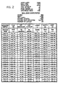
- the data used to arrive at the numbers shown in Fig. 2 was derived from a dipmeter survey of a hyperboloidal structure of revolution.
- the apex of the structure was 4000 meters below sea-level, and at 2000 meters north and 650 meters west of a surface reference point.
- the apex was penetrated by the well head for the wellbore at 555 meters north and 632 meters west of the surface reference point, and 345 meters below sea level. Fitted functions of the present method were used to derive this data.
- dip magnitude is the angle between the vertical plane and that unit vector
- dip azimuth is the angle in the horizontal plane measured clockwise between true north and the projection of that unit vector on the horizontal plane.
- Fig. 2 Sample coordinates and measurements for stacked hyperboloids of revolution penetrated by a deviated borehole are set forth in Fig. 2.
- the initial hypothetical values of the well location and coordinates are listed above the table.
- the well coordinates are calculated by a true radius of curvature method.
- the values of total vertical depth (TVD), x and y define the three dimensional space, where x defines the North coordinate and y defines the East coordinate.
- TVD is the equivalent of z in parametric function F.
- Parameter ⁇ is determined according to the mathematical model for the three dimensional space at each measured depth.
- Each point (x,y,TVD) of the borehole has a value in the three-dimensional space.
- the resulting dip profile of the dip magnitude and corresponding borehole deviation are graphically displayed in the arrow plots as shown in Fig. 3.
- the dips are shown on these plots as "tadpoles" which are small circles with lines or tails emanating therefrom.
- the computed dips of Fig. 2 are shown in an "arrow plot" form.
- the position of the small circles on the arrow plot shows the measured depth at which the dip occurs in the borehole against the dip magnitude.
- the direction of the tail shows the dip azimuth.
- the borehole deviation measured values are displayed.
- the small circles show the measured depth against the borehole deviation
- the direction of the tail shows the direction of the borehole with respect to true north.
- Subsurface geological structures may be faulted at arbitrary locations. Faults are individual accidents, which are by nature unpredictable. Faults must be incorporated into the model at hypothetical locations. Suspect fault locations may be determined from an analysis of surface studies. Various factors to be considered in determining these hypothetical locations are the dip of the fault plane; its intercept with the borehole, if any; and the fault "throw,” both in extent and in direction, as “normal” for gravity slippage, “reverse” for upward slippage, “thrust” for horizontal overriding, and “strike” or “transcurrent” for horizontal slippage along the strike of the fault. The throw is the amount one block of fault has been displaced. Calculation of the model is initiated in an arbitrarily selected half space relative to the fault, and is continued beyond the fault in its other half space by the simple addition of the translation vector described by the throw. The vector may or may not be constant along the face of the fault.
Landscapes
- Geology (AREA)
- Physics & Mathematics (AREA)
- Life Sciences & Earth Sciences (AREA)
- Engineering & Computer Science (AREA)
- Mining & Mineral Resources (AREA)
- General Life Sciences & Earth Sciences (AREA)
- Fluid Mechanics (AREA)
- Environmental & Geological Engineering (AREA)
- Geophysics (AREA)
- Geochemistry & Mineralogy (AREA)
- Geophysics And Detection Of Objects (AREA)
- Electrical Discharge Machining, Electrochemical Machining, And Combined Machining (AREA)
- Constituent Portions Of Griding Lathes, Driving, Sensing And Control (AREA)
- Manufacture, Treatment Of Glass Fibers (AREA)
- Earth Drilling (AREA)
- Control Of Position, Course, Altitude, Or Attitude Of Moving Bodies (AREA)
Claims (9)
- Verfahren zur Unterstützung der genauen geometrischen Beschreibung einer gefalteten unterirdischen geologischen Struktur unter Verwendung eines Computers und von Daten einer kontinuierlichen Neigungsfolge aus einer mittels Neigungsmesser vorgenommenen Vermessung, die in einem durch die geologische Struktur verlaufenden Bohrloch erhalten wird, wobei das Verfahren die folgenden Schritte umfasst:dadurch gekennzeichnet, dass bei der Erhaltung der Schätzwerte der geometrischen Parameter eine kontinuierliche Beschreibung des Bohrlochverlaufs in dem dreidimensionalen Referenzrahmen verwendet wird, wobei die kontinuierliche Beschreibung des Bohrlochverlaufs für eine wahre vertikale Tiefe eingestellt wird, wodurch das Verfahren sowohl auf abgelenkte Bohrlöcher als auch auf vertikale Bohrlöcher angewendet werden kann.Erhalten von Schätzwerten geometrischer Parameter aus der mittels Neigungsmesser vorgenommenen Vermessung, die die geologische Struktur als eine Schichtung von Flächen beschreiben, die in einem dreidimensionalen Bezugsrahmen durch eine Parameterfunktion repräsentiert werden;Erzeugen theoretischer Neigungsprofile unter Verwendung der Schätzwerte längs eines gegebenen Bohrlochverlaufs aus mehreren möglichen mathematischen Lösungen, die für die geologische Struktur passen;Erzeugen kritischer Zahlen, um die Auswahl eines Lösungsmodells aus den mehreren möglichen Lösungen zu ermöglichen; undEinstellen des Wertes der Schätzwerte in iterativer Weise, um ein endgültiges Neigungsprofil, das die höchste Korrelation mit der kontinuierlichen Neigungsfolge von der mittels Neigungsmesser vorgenommenen Vermessung besitzt, zu erzeugen und anzuzeigen;
- Verfahren nach Anspruch 1, bei dem die Parameterfunktion eine raumfüllende dreidimensionale Parameterfunktion mit nicht negativem Gradienten ist.
- Verfahren nach Anspruch 1, bei dem der Schritt des Erhaltens von Schätzwerten der geometrischen Parameter ferner das Erzeugen kritischer Parameterzahlen umfasst, um die Auswahl der dreidimensionalen Parameterfunktion zu unterstützen.
- Verfahren nach Anspruch 1, bei dem die geometrische Struktur mehrere Fehler enthält, die in der dreidimensionalen Referenz beschreibbar sind.
- Verfahren nach Anspruch 1, bei dem eine Gradientengröße über die Schichtung von Flächen kontinuierlich angezeigt wird, um Zonen einer wahrscheinlichen Druckentspannung, die einer erhöhten Porosität zugeordnet ist, zu identifizieren.
- Verfahren nach Anspruch 1, bei dem aus dem Lösungsmodell graphische Anzeigen abgeleitet werden.
- Verfahren nach Anspruch 1, bei dem die Schätzwerte unter der Bedingung der Erhaltung der Dicke erhalten werden.
- Verfahren nach Anspruch 1, bei dem die Parameterfunktion eine raumfüllende dreidimensionale Parameterfunktion mit nicht negativen Gradienten ist, die geschichtete, rotationssymmetrische Kegel definiert.
- Verfahren nach Anspruch 1, bei dem die geometrischen Parameter aus der Gruppe ausgewählt sind, die aus dem axialen Ort der Ebene und der Neigung, der Elliptizität, dem minimalen Krümmungsradius, der Eindringtiefe und der Öffnung besteht.
Applications Claiming Priority (3)
| Application Number | Priority Date | Filing Date | Title |
|---|---|---|---|
| US08/191,127 US5388044A (en) | 1994-02-03 | 1994-02-03 | Dipmeter processing technique |
| PCT/US1995/000004 WO1995021390A1 (en) | 1994-02-03 | 1995-01-04 | Dipmeter processing technique |
| US191127 | 2002-07-09 |
Publications (4)
| Publication Number | Publication Date |
|---|---|
| EP0803073A1 EP0803073A1 (de) | 1997-10-29 |
| EP0803073A4 EP0803073A4 (de) | 1999-09-01 |
| EP0803073B1 true EP0803073B1 (de) | 2004-07-28 |
| EP0803073B8 EP0803073B8 (de) | 2004-12-01 |
Family
ID=22704246
Family Applications (1)
| Application Number | Title | Priority Date | Filing Date |
|---|---|---|---|
| EP95906738A Expired - Lifetime EP0803073B8 (de) | 1994-02-03 | 1995-01-04 | Verarbeitung von Daten eines Neigungsmessers |
Country Status (6)
| Country | Link |
|---|---|
| US (1) | US5388044A (de) |
| EP (1) | EP0803073B8 (de) |
| AT (1) | ATE272223T1 (de) |
| AU (1) | AU1520995A (de) |
| DE (1) | DE69533318D1 (de) |
| WO (1) | WO1995021390A1 (de) |
Families Citing this family (11)
| Publication number | Priority date | Publication date | Assignee | Title |
|---|---|---|---|---|
| US5905657A (en) * | 1996-12-19 | 1999-05-18 | Schlumberger Technology Corporation | Performing geoscience interpretation with simulated data |
| US6047240A (en) * | 1998-01-16 | 2000-04-04 | Schlumberger Technology Corporation | Method and apparatus for evaluating the resistivity of invaded formations at high apparent dip angle |
| US6415231B1 (en) | 2000-08-14 | 2002-07-02 | Joel J. Hebert | Method and apparatus for planning and performing a pressure survey |
| US7630872B2 (en) * | 2004-09-16 | 2009-12-08 | Schlumberger Technology Corporation | Methods for visualizing distances between wellbore and formation boundaries |
| US9036450B2 (en) * | 2010-04-12 | 2015-05-19 | Schlumberger Technology Corporation | Generating an image of a subterranean structure |
| US8793113B2 (en) | 2010-05-14 | 2014-07-29 | Schlumberger Technology Corporation | Method and apparatus for near well structural modeling based on borehole dips |
| CN103282797B (zh) * | 2011-01-05 | 2016-08-24 | 兰德马克绘图国际公司 | 计算断层落差的方法及系统 |
| US10444405B2 (en) * | 2013-01-28 | 2019-10-15 | Schlumberger Technology Corporation | Systems and methods for curvature analysis from borehole dips and applications thereof |
| US10753918B2 (en) * | 2014-12-15 | 2020-08-25 | Saudi Arabian Oil Company | Physical reservoir rock interpretation in a 3D petrophysical modeling environment |
| CN108256130B (zh) * | 2016-12-28 | 2021-07-20 | 核工业北京地质研究院 | 一种地质钻孔空间轨迹还原方法 |
| CN114898057B (zh) * | 2022-05-18 | 2024-04-23 | 青海省地质测绘地理信息院 | 地质剖面图三维空间信息提取方法和装置、存储介质 |
Family Cites Families (9)
| Publication number | Priority date | Publication date | Assignee | Title |
|---|---|---|---|---|
| US4357660A (en) * | 1973-05-01 | 1982-11-02 | Schlumberger Technology Corporation | Formation dip and azimuth processing technique |
| US4348748A (en) * | 1974-12-30 | 1982-09-07 | Schlumberger Technology Corporation | Dipmeter displacement processing technique |
| US4303975A (en) * | 1974-12-30 | 1981-12-01 | Schlumberger Technology Corporation | Dipmeter displacement qualifying technique |
| US4414656A (en) * | 1980-04-15 | 1983-11-08 | Schlumberger Technology Corporation | Well logging system for mapping structural and sedimentary dips of underground earth formations |
| US4852005A (en) * | 1987-04-03 | 1989-07-25 | Amoco Corporation | Method of computing formation dip and azimuth |
| US4942528A (en) * | 1987-06-18 | 1990-07-17 | Halliburton Logging Services Inc. | Dipmeter processing technique |
| US4853855A (en) * | 1987-06-18 | 1989-08-01 | Halliburton Logging Services Inc. | Dipmeter processing technique |
| US4873636A (en) * | 1987-10-26 | 1989-10-10 | Amoco Corporation | Interpretation of conical structures from dipmeter surveys |
| US4939649A (en) * | 1988-07-29 | 1990-07-03 | Amoco Corporation | Method of correcting nonunimodality of dipmeter traces by uniquely transforming individual traces or intervals |
-
1994
- 1994-02-03 US US08/191,127 patent/US5388044A/en not_active Expired - Lifetime
-
1995
- 1995-01-04 AU AU15209/95A patent/AU1520995A/en not_active Abandoned
- 1995-01-04 WO PCT/US1995/000004 patent/WO1995021390A1/en not_active Ceased
- 1995-01-04 EP EP95906738A patent/EP0803073B8/de not_active Expired - Lifetime
- 1995-01-04 AT AT95906738T patent/ATE272223T1/de not_active IP Right Cessation
- 1995-01-04 DE DE69533318T patent/DE69533318D1/de not_active Expired - Lifetime
Non-Patent Citations (1)
| Title |
|---|
| BENGSTON C.A.: "STRUCTURAL USES OF TANGENT DIAGRAMS", GEOLOGY, vol. 8, pages 599 - 602, XP000917672, DOI: doi:10.1130/0091-7613(1980)8<599:SUOTD>2.0.CO;2 * |
Also Published As
| Publication number | Publication date |
|---|---|
| EP0803073A1 (de) | 1997-10-29 |
| EP0803073B8 (de) | 2004-12-01 |
| WO1995021390A1 (en) | 1995-08-10 |
| ATE272223T1 (de) | 2004-08-15 |
| AU1520995A (en) | 1995-08-21 |
| US5388044A (en) | 1995-02-07 |
| DE69533318D1 (de) | 2004-09-02 |
| EP0803073A4 (de) | 1999-09-01 |
Similar Documents
| Publication | Publication Date | Title |
|---|---|---|
| US9081918B2 (en) | Methods and systems regarding models of underground formations | |
| WO2020080973A1 (ru) | Способ и система комбинированного сопровождения процесса бурения скважины | |
| US10782433B2 (en) | Method for an automatic detection of acoustic reflectors and their parameters from borehole acoustic array data | |
| US7663968B2 (en) | Method of processing geological data | |
| CN106368691A (zh) | 基于岩石物理地震信息三维异常孔隙压力预测方法 | |
| RU2720115C1 (ru) | Способ автоматизированного процесса геологической проводки скважин и система для его осуществления | |
| Barton et al. | Characterising the full stress tensor based on observations of drilling-induced wellbore failures in vertical and inclined boreholes leading to improved wellbore stability and permeability prediction | |
| EP0803073B1 (de) | Verarbeitung von Daten eines Neigungsmessers | |
| WO2004095070A2 (en) | Seismic p-wave velocity derived from vibrator control system | |
| US6073079A (en) | Method of maintaining a borehole within a multidimensional target zone during drilling | |
| US6711529B1 (en) | Method for determining at least one optimal trajectory for reaching a fuzzy target situated in a medium starting from a point remote from the target | |
| US11965996B2 (en) | Generating low frequency models for seismic waveform inversion in formation regions with limited control wells | |
| CN110088647A (zh) | 改进的结构建模 | |
| NO344460B1 (en) | Methods and systems for identifying and plugging subterranean conduits | |
| Hazeu et al. | The application of new approaches for shale management in a three-dimensional simulation study of the Frigg Field | |
| CN106990433B (zh) | 一种隆起区微小侵蚀沟槽的识别方法 | |
| US12352915B2 (en) | Method and system for estimating converted-wave statics | |
| US12422582B2 (en) | Updating subsurface structural maps with well-measured orientation data while preserving local geological structures | |
| Aminzadeh et al. | Geophysics in drilling | |
| US12436305B2 (en) | Automatic tying structure maps of subsurface horizons to well-derived orientation information | |
| WO2025175409A1 (en) | Method and system for rock physics-based grid refinement of grid in forward stratigraphic modeling | |
| WO2025166753A1 (en) | Methods and systems for seismic-conditioned process-based geological models using multi-point statistics | |
| Hakim et al. | Subsurface velocity measurement | |
| Wilczynski et al. | Drill‐bit position monitoring using seismic‐while‐drilling data; numerical and field examples from Sweden | |
| Beyer et al. | Basic data and preliminary density and porosity profiles for twelve borehole gravity surveys made in the Los Angeles, San Joaquin, Santa Maria and Ventura Basins, California |
Legal Events
| Date | Code | Title | Description |
|---|---|---|---|
| PUAI | Public reference made under article 153(3) epc to a published international application that has entered the european phase |
Free format text: ORIGINAL CODE: 0009012 |
|
| 17P | Request for examination filed |
Effective date: 19960828 |
|
| AK | Designated contracting states |
Kind code of ref document: A1 Designated state(s): AT DE DK ES FR GB IT NL |
|
| RAP1 | Party data changed (applicant data changed or rights of an application transferred) |
Owner name: SCHLUMBERGER HOLDINGS LIMITED |
|
| A4 | Supplementary search report drawn up and despatched |
Effective date: 19990721 |
|
| AK | Designated contracting states |
Kind code of ref document: A4 Designated state(s): AT DE DK ES FR GB IT NL |
|
| 17Q | First examination report despatched |
Effective date: 20000821 |
|
| GRAP | Despatch of communication of intention to grant a patent |
Free format text: ORIGINAL CODE: EPIDOSNIGR1 |
|
| RTI1 | Title (correction) |
Free format text: DIPMETER PROCESSING TECHNIQUE |
|
| GRAS | Grant fee paid |
Free format text: ORIGINAL CODE: EPIDOSNIGR3 |
|
| GRAA | (expected) grant |
Free format text: ORIGINAL CODE: 0009210 |
|
| AK | Designated contracting states |
Kind code of ref document: B1 Designated state(s): AT DE DK ES FR GB IT NL |
|
| PG25 | Lapsed in a contracting state [announced via postgrant information from national office to epo] |
Ref country code: IT Free format text: LAPSE BECAUSE OF FAILURE TO SUBMIT A TRANSLATION OF THE DESCRIPTION OR TO PAY THE FEE WITHIN THE PRE;WARNING: LAPSES OF ITALIAN PATENTS WITH EFFECTIVE DATE BEFORE 2007 MAY HAVE OCCURRED AT ANY TIME BEFORE 2007. THE CORRECT EFFECTIVE DATE MAY BE DIFFERENT FROM THE ONE RECORDED.SCRIBED TIME-LIMIT Effective date: 20040728 Ref country code: AT Free format text: LAPSE BECAUSE OF FAILURE TO SUBMIT A TRANSLATION OF THE DESCRIPTION OR TO PAY THE FEE WITHIN THE PRESCRIBED TIME-LIMIT Effective date: 20040728 |
|
| REG | Reference to a national code |
Ref country code: GB Ref legal event code: FG4D |
|
| REF | Corresponds to: |
Ref document number: 69533318 Country of ref document: DE Date of ref document: 20040902 Kind code of ref document: P |
|
| RIN2 | Information on inventor provided after grant (corrected) |
Inventor name: HEPP, VINCENT R. |
|
| PG25 | Lapsed in a contracting state [announced via postgrant information from national office to epo] |
Ref country code: DK Free format text: LAPSE BECAUSE OF FAILURE TO SUBMIT A TRANSLATION OF THE DESCRIPTION OR TO PAY THE FEE WITHIN THE PRESCRIBED TIME-LIMIT Effective date: 20041028 |
|
| PG25 | Lapsed in a contracting state [announced via postgrant information from national office to epo] |
Ref country code: DE Free format text: LAPSE BECAUSE OF FAILURE TO SUBMIT A TRANSLATION OF THE DESCRIPTION OR TO PAY THE FEE WITHIN THE PRESCRIBED TIME-LIMIT Effective date: 20041029 |
|
| PG25 | Lapsed in a contracting state [announced via postgrant information from national office to epo] |
Ref country code: ES Free format text: LAPSE BECAUSE OF FAILURE TO SUBMIT A TRANSLATION OF THE DESCRIPTION OR TO PAY THE FEE WITHIN THE PRESCRIBED TIME-LIMIT Effective date: 20041108 |
|
| ET | Fr: translation filed | ||
| PLBE | No opposition filed within time limit |
Free format text: ORIGINAL CODE: 0009261 |
|
| STAA | Information on the status of an ep patent application or granted ep patent |
Free format text: STATUS: NO OPPOSITION FILED WITHIN TIME LIMIT |
|
| 26N | No opposition filed |
Effective date: 20050429 |
|
| PGFP | Annual fee paid to national office [announced via postgrant information from national office to epo] |
Ref country code: NL Payment date: 20140110 Year of fee payment: 20 |
|
| PGFP | Annual fee paid to national office [announced via postgrant information from national office to epo] |
Ref country code: FR Payment date: 20140108 Year of fee payment: 20 |
|
| PGFP | Annual fee paid to national office [announced via postgrant information from national office to epo] |
Ref country code: GB Payment date: 20140102 Year of fee payment: 20 |
|
| REG | Reference to a national code |
Ref country code: NL Ref legal event code: V4 Effective date: 20150104 |
|
| REG | Reference to a national code |
Ref country code: GB Ref legal event code: PE20 Expiry date: 20150103 |
|
| PG25 | Lapsed in a contracting state [announced via postgrant information from national office to epo] |
Ref country code: GB Free format text: LAPSE BECAUSE OF EXPIRATION OF PROTECTION Effective date: 20150103 |