EP0803071B1 - All-optical, rapid readout, fiber-coupled thermoluminescent dosimeter system - Google Patents
All-optical, rapid readout, fiber-coupled thermoluminescent dosimeter system Download PDFInfo
- Publication number
- EP0803071B1 EP0803071B1 EP95927289A EP95927289A EP0803071B1 EP 0803071 B1 EP0803071 B1 EP 0803071B1 EP 95927289 A EP95927289 A EP 95927289A EP 95927289 A EP95927289 A EP 95927289A EP 0803071 B1 EP0803071 B1 EP 0803071B1
- Authority
- EP
- European Patent Office
- Prior art keywords
- thermoluminescent
- dosimeter
- radiation
- light
- glass
- Prior art date
- Legal status (The legal status is an assumption and is not a legal conclusion. Google has not performed a legal analysis and makes no representation as to the accuracy of the status listed.)
- Expired - Lifetime
Links
Images


Classifications
-
- G—PHYSICS
- G01—MEASURING; TESTING
- G01T—MEASUREMENT OF NUCLEAR OR X-RADIATION
- G01T1/00—Measuring X-radiation, gamma radiation, corpuscular radiation, or cosmic radiation
- G01T1/02—Dosimeters
- G01T1/10—Luminescent dosimeters
- G01T1/11—Thermo-luminescent dosimeters
- G01T1/115—Read-out devices
-
- A—HUMAN NECESSITIES
- A61—MEDICAL OR VETERINARY SCIENCE; HYGIENE
- A61N—ELECTROTHERAPY; MAGNETOTHERAPY; RADIATION THERAPY; ULTRASOUND THERAPY
- A61N5/00—Radiation therapy
- A61N5/10—X-ray therapy; Gamma-ray therapy; Particle-irradiation therapy
- A61N5/1048—Monitoring, verifying, controlling systems and methods
Definitions
- the present invention relates to dosimeters and particularly to a new type of rapid-readout, thermoluainescent dosimeter for the remote monitoring of radiation sources, such as ultraviolet, x-ray or gamma radiation, using a radiation-sensitive glass material (dosimeter) in conjunction with fiber optic components.
- radiation sources such as ultraviolet, x-ray or gamma radiation
- thermoluainescent dosimeter for the remote monitoring of radiation sources, such as ultraviolet, x-ray or gamma radiation
- Thermoluminescent (TL) materials have been used for many years to monitor radiation exposure levels. These dosimeters measure the accumulated radiation exposure over a period of time, ranging from minutes, to days to years.
- Materials such as metal-ion-activated Lithium Fluoride (LiF), or Calcium Fluoride (CaF 2 ) are commonly used in "film badges" to monitor personnel exposure to radiation. These materials are generally prepared from powders that are pressed into opaque white pellets. When exposed to ionizing radiation, such as deep ultraviolet, x-ray or gamma radiation, free electrons are generated and are trapped in the material. The electrons remain trapped until a source of heat is applied to the material to stimulate the release of the electrons. The electrons recombine with an ion in the material resulting in the emission of light. The amount of light emitted is proportional to the amount of radiation exposure.
- ionizing radiation such as deep ultraviolet, x-ray or gamma radiation
- TLD Thermoluminescent dosimetry
- TLD time difference detection
- Glass materials have been studied for radiation dosimetry measurements. With some glasses, radiation exposure leads to darkening of the glass and the degree of darkening is used as a measure of the radiation dose. Thermoluminescent glasses have also been reported. The effectiveness of these glasses for TLD applications has been limited for a number of reasons, including low readout temperatures, low sensitivity compared to crystalline phosphors and low saturation doses.
- Fiber optic TLD systems have also been described, see, eg, US-A-5 030 834.
- One system utilizes traditional TL phosphors attached to the end of a 0.6 mm diameter optical fiber.
- An absorbing material is applied to one surface of the phosphor and a diode laser is used to heat the absorber which in turn heats the TL material by diffusive heating.
- This system is described as a remote fiber optic laser TLD system.
- the performance of the system is limited in several ways.
- the TL material must be very thin, approximately 0.1 mm, to allow the laser heating source to be transmitted through the TL material to the absorber material.
- the diameter of the TL material must be fairly large.
- the diameter of the optical fiber must also be large to match the size of the TL dosimeter.
- a laser heating method has been described for the heating of TL materials stacked in layers.
- a CO 2 laser was used as the heat source. This does provide for rapid, efficient heating but is impractical for fiber optic applications because ordinary optical fibers are not transparent to CO 2 laser wavelengths, and specialty, CO 2 -transmitting fibers are of limited utility, having large diameters(0.7 to 2mm diameter), limited transparency for visible light wavelengths that correspond to the thermoluminescence and are very expensive (one meter of fiber costs approximately $1000, 10 meters cost $5500).
- Another object of the invention is to provide a dosimeter apparatus for the remote monitoring of radiation sources such as deep ultraviolet, x-ray and gamma radiation.
- a further object of the invention is to provide a rapid-readout, thermoluminescent dosimeter for the remote monitoring of radiation sources using a radiation-sensitive glass material (dosimeter) in conjunction with fiber optic components.
- thermoluminescent radiation dosimeter system according to claim 1 where by a radiation-sensitive thermoluminescent dosimeter which utilizes a new, semiconductor-doped glass material is disposed at a remote location for storing energy from ionizing radiation when exposed thereto and for releasing the stored energy in the form of thermoluminescence light at a first wavelength when stimulated by exposure to light energy at a predetermined stimulating second wavelength.
- a radiation-sensitive thermoluminescent dosimeter which utilizes a new, semiconductor-doped glass material is disposed at a remote location for storing energy from ionizing radiation when exposed thereto and for releasing the stored energy in the form of thermoluminescence light at a first wavelength when stimulated by exposure to light energy at a predetermined stimulating second wavelength.
- thermoluminescent dosimeter system described in this invention utilizes a novel, semiconductor-doped glass material that was recently developed by the present inventors and described in the Navy Case No. 76,342.
- This semiconductor-doped glass material consists of nanometer-sized, zinc sulfide crystals, activated with copper ions. Exposure to ionizing radiation, such as deep ultraviolet, x-ray or gamma radiation, results in the formation of trapped electrons in the composite glass material. The electrons remain trapped until the temperature of the material is raised to approximately 150 degrees C. At this temperature, some of the trapped electrons recombine with the copper ions, producing green light with a wavelength of approximately 500 nanometers (nm). It is assumed that the thermoluminescence spectrum is similar to the ultraviolet (UV) excited photoluminescence spectrum.
- Fig. 1 shows the photoluminescence spectum of an exemplary material, zinc sulfide (ZnS) doped with copper (Cu) nanocrystals (ZnS:Cu), in a VycorTM glass excited with a laser pulse (to be discussed).
- ZnS zinc sulfide
- Cu copper
- ZnS:Cu copper
- the wavelength range in Fig. 1 that is emitted by this exemplary ZnS:Cu semiconductor-doped glass material is good for commercial thermoluminescence measuring devices. Most of such devices are sensitive to wavelengths in this wavelength range. Redder wavelengths are often not preferred due to interference with black-body emission, but they can be used.
- the dosimeter system of the invention can be modified to read redder emissions.
- the exemplary ZnS:Cu semiconductor-doped glass material absorbs ultraviolet light at about 266 nanometers (nm) and, as indicated in Fig. 1, emits that photoluminescence in a broadband ranging from about 400 nm to about 620 nm and has a peak intensity at about 500 nm (with a color that appears to be blue-green).
- Fig. 2 shows the intensity of the thermoluminescence emission from the exemplary ZnS:Cu semiconductor-doped glass material as a function of the temperature. More specifically, Fig. 2 shows the thermoluminescence glow curve of the ZnS doped with Cu in VycorTM glass after being exposed to 20 grays (Gy) exposure of, for example, cobalt 60 gamma radiation. The spectrum shown in Fig. 2 was then obtained by heating the exemplary ZnS:Cu semiconductor-doped glass material at a constant rate over the temperature range from about 50 degrees centrigrade(C) to about 350 degrees C and then measuring the thermoluminescence output with a photomultiplier tube (not shown).
- the glow curve of Fig. 2 shows a beginning of the thermoluminescent (TL) signal at approximately 100 degrees C and then two peaks. A first peak occurs at approximately 160 degrees C and a second peak occurs at about 220 degrees C. As the temperature is increased, more light is released, until about 350 degrees C. At this point, all of the formerly trapped electrons have recombined with copper ions, and no additional light is produced.
- the exemplary ZnS:Cu semiconductor-doped glass material can then be used again for another radiation dose measurement.
- Fig. 3 illustrates the dose-dependent performance of the exemplary thermoluminescent ZnS:Cu glass dosimeter material of the invention. This is a plot of the total thermoluminescent light output as a function of Cobalt 60 gamma ray radiation dose over the range from about 10 -4 gray (Gy) to almost 10 3 Gy. The thermoluminescent (TL) signal was observed to be linear over a wide range of (almost seven orders of magnitude) of exposures.
- Fig. 4 shows a comparison of the performance of the thermoluminescent dosimeter glass material ZnS:Cu shown in Fig. 3 with the performance of the well-known dosimeter material TLD-100.
- the five dark circles represent a plot of the thermoluminescent signal vs Dose in Gy to illustrate the performance of the thermoluminescent glass material ZnS:Cu shown in Fig. 3, whereas the four light circles represent a plot of the thermoluminescent signal vs Dose in Gy to illustrate the performance of the well-known dosimeter material TLD-100.
- TLD-100 is a lithium fluoride dosimeter which is activated by magnesium and titanium.
- TLD-100 is a dosimeter with a very good sensitivity which produces a good thermoluminescent signal.
- the new ZnS:Cu glass phosphor material of the dosimeter used in the invention has even a better sensitivity than the well-known, dosimeter phospher TLD-100 material has.
- thermoluminescent dosimeter system 15 includes a central monitoring station 20, a remotely positioned, optically-transparent, thermoluminescent (TL) glass dosimeter 17 and an optical fiber or fiberoptic cable 27 which couples the central monitoring station 20 to the TL dosimeter 17.
- the central monitoring station 20 includes an optical source 21, a dichroic beam splitter 23, a focusing lens 25, a filter 31 and a thermoluminescent (TL) detector 33.
- TL thermoluminescent
- the optically-transparent thermoluminescent (TL) glass dosimeter 17 contains the thermoluminescent glass dosimeter material described above in relation to Figs. 1-4.
- the thermoluminescent glass dosimeter material incorporates an absorber or dopant (not shown), such as Neodymium (Nd), Ytterbium (Yb), or Erbium (Er) rare earth ions, or a combination of such absorbers, to absorb the light energy from the optical source 21 (to be explained).
- the absorber is chosen to be transparent in the wavelength region of the thermoluminescent emission from the glass dosimeter 17 (to be explained).
- the concentration of the absorber (or combination of absorbers) in the TL dosimeter 17 can be adjusted depending on the desired length of the dosimeter 17. High absorber concentrations result in the absorption of all of the light energy from the optical source 21 in a short length of the dosimeter 17. Low concentrations of absorber allow for the use of a longer dosimeter 17.
- Rare earth ions often have high fluorescence yields that tend to reduce the heating efficiency. The use of high concentrations reduces the fluorescence yield and enhances the heating efficiency. For the case of the Nd ion dopant, a concentration of between 4% and 7& is desirable.
- thermoluminescent (TL) dosimeter 17 may be in the form of a rod, fiber, plate or tube. An end of the glass dosimeter 17 may contain an optional broadband reflective coating 19.
- thermoluminescent dosimeter system 15 of Fig. 5 0.8 to 10 micron light from the optical source 21 (which may be, for example, a diode laser in the range of 0.8 microns to 10 microns, a gas laser, a molecular laser or a solid state laser) and at an exemplary 830 nanometer (nm) wavelength is passed through the dichroic beam splitter 23 and focused by the lens 25 into the optical fiber or fiberoptic cable 27 which may be, for example, several kilometers in length.
- the optical fiber 27 is fused at its far end 29 to the dosimeter glass material of the thermoluainescent dosimeter 17 so that the dosimeter glass material effectively becomes a part of the optical fiber 27.
- the optical fiber 27 directs light energy from the laser diode 21 to the thermoluminescent material in the TL dosimeter 17. It is preferrable that the TL glass dosimeter 17 and the optical fiber 27 have substantially identical end face configurations at the far end 29 of the optical fiber 27 to maximize the transfer of light energy from the optical fiber 27 into the TL glass dosimeter 17.
- the exemplary 830 nm laser light entering the TL glass dosimeter 17 is absorbed efficiently by the rare earth ions in the light-absorbing dopant, selected from, for example, Nd, Yb, or Er, and is transformed into heat. This heat is sufficient to stimulate blue-green thermoluminescence at a wavelength of about 500 nm (as shown in Fig. 1) in the TL glass material in the dosimeter 17 that has been previously irradiated with ionizing radiation from some radiation source (not shown) of, for example, deep ultraviolet, x-ray or gamma radiation.
- some radiation source not shown
- the optical source 21 can be any type of light source (such as the previously-mentioned exemplary diode laser, molecular laser or solid state laser) which can provide light energy at an appropriate light wavelength sufficient to heat the thermoiuminescent glass material in the thermoluminescent glass dosimeter 17 to produce thermoluminescent emissions.
- any type of light source such as the previously-mentioned exemplary diode laser, molecular laser or solid state laser
- thermoluminescence light in the dosimeter 17 is directed back through the optical fiber 27, collimated by the lens 25 and passed to the dichroic beam splitter 23.
- the optional broadband reflective coating 19 is disposed at an end of the glass dosimeter 17, the reflective coating 19 will minimize any loss of thermoluminescence light out of the far end of the dosimeter 17 by reflecting it back to the optical fiber 27, and even more thermoluminescence light will be directed back to the beam splitter 23.
- the dichroic beam splitter 23 is designed to transmit the 830 nm semiconductor laser light therethrough and reflect the 500 nm blue-green light from the TL dosimeter 17.
- the reflected 500 nm TL light is filtered by the filter 31 to remove background light, or photoluminescence from the absorbing species, and is detected by the thermoluminescent detector 33 which is sensitive to light in the range from about 450 nm to about 550 nm.
- the thermoluminescent detector 33 which may be a photomultiplier tube, a photodiode or any other suitable photodetector, measures the thermoluminescent emissions from the TL glass dosimeter 17.
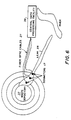
- Fig. 6 illustrates a first exemplary application of the thermoluminescent dosimeter system of the invention in the monitoring of nuclear contamination from a waste depository. Monitoring ground water contamination around nuclear facilities is an important problem.
- the TL glass dosimeter 17 of Fig. 5 is capable of withstanding harsh environments. As shown in Fig. 6, a series of these fiber-coupled dosimeters 17 could be buried underground at various locations around a nuclear waste storage facility to monitor nuclear waste seepage or a leak 35 from a waste depository 37.
- the dosimeters 17 could be linked by associated fiberoptic cables to a central monitoring station 39, similar to the central monitoring station 20 in Fig. 1.
- a computer-controlled X-Y translator (not shown) in the monitoring station 39 could then selectively position each optical fiber to accept the light from the light source 21 (Fig. 5) to selectively interrogate the dosimeters 17 from that central monitoring station 39. This could reduce the cost of various problems associated with sampling nuclear waste materials.
- the dosimeters 17 are reusable after they are interrogated.
- thermoluminescent emission data that indicates the amount of radiation that the thermoluminescent glass dosimeter system 15 of the invention has been exposed to can be read out any number of times with the diode laser 21 (Fig. 5) to interrogate the system 15.
- the system 15 can be interrogated hourly, daily, weekly, monthly, yearly, or at any other desired time. It doesn't matter.
- the thermoluminescent glass material in the dosimeter system 15 is very rugged, so that it can survive being buried for long periods of time.
- the direction of a nuclear leak 35 and the quantity of nuclear contamination can be mapped out by taking several measurements from the different dosimeters 17.
- a single diode laser 21 Fig.
- thermoluminescent detector 33 (Fig. 5) and a single thermoluminescent detector 33 (Fig. 5) can be used with the laser light being selectively directed to each of the different fiber optic cables 27, thus drastically reducing the number of diode lasers, to even only one laser diode, to monitor an entire array of dosimeters 15.
- only one diode laser 21 (Fig. 5) and only one TL detector 33 (Fig. 5) are required to access a large number of thermoluminescent glass dosimeters 17 disposed in a large area to be monitored, tremendously reducing the cost of the dosimeter system of the invention.
- Fig. 7 illustrates a second exemplary application of the thermoluminescent dosimeter system of the invention for in vivo radiation monitoring of radiation doses in a patient 40 undergoing radiation therapy.
- thermoluminescent dosimeter 17 can be spliced to the end of an optical fiber 27 and used in conjunction with a fiber catheter 28 to introduce the dosimeter inside the body of a human patient 40.
- the thermoluminescent dosimeter 17 can be directed to a certain portion of the human body that is being exposed to radiation as, for example, in radiation therapy for cancer treatment.
- the dosimeter 17 can be placed next to a tumor that is being irradiated and provide the physician with an immediate feedback as to how much of a radiation dose that he is applying to the tumor during radiation therapy. This would allow more precise control of radiation doses and help reduce collateral damage to healthy tissues.
- the fiber catheter 28 can be left in the body of the patient 40 and disconnected from the laser diode 21 and TL detector 33 by using an optical coupler (not shown). In that way the catheter 28 would only have to be inserted one time and the patient 40 could return to the physician for his weekly treatments. After the treatments have been completed, the catheter 28 could be removed at that time. This reduces the cost of catherization, which is quite expensive.
- thermoluminescent dosimeter system of the invention For a better understanding of the fiber-coupled thermoluminescent dosimeter system of the invention, the new semiconductor-doped glass material that was recently developed by the present inventors will now be discussed. However, the absorbant dopant of Nd, Yb, or Er ions that is added to the new glass material to provide an absorbing medium for the light from the diode laser 21 will not be discussed, since the doping of a material with rare earth ions is well known in the art.
- the nanocrystalline inorganic solid/glass composite phosphors are fabricated by deposition of the inorganic solid and the activators within a porous glass matrix.
- the deposition can be accomplished using known chemical methods for doping glasses, such as, for example, precipitation from a liquid phase solution, or CVD. Often, the most convenient method will be precipitation from a liquid phase solution.
- the exact deposition process used and the parameters employed for deposition are not critical, provided that the deposited materials are nanocrystalline and the glass retains its porosity.
- the size of the deposited crystals is controlled by the pore size of the glass into which the crystals are deposited. The pores restrict the growth of the deposited crystals so that the deposited crystals have a diameter smaller than that of the pore in which they precipitate.
- the pores in a porous glass are in reality tortuous channels, sometimes interconnected, which behave like pores.
- the concentration of the dopants within the glass becomes too great for the average effective pore size, the nanocrystals will grow through the channels, interconnect, and develop into large crystals that reduce the transparency of the glass.
- a thermal heat treatment may be used to promote diffusion of the activators in the nanocrystals and to control the nature and quality of the crystalline phase. This heat treatment is performed at a temperature sufficient to substantially enhance diffusion of the activators.
- the activation temperature is also selected to partially, or perhaps even fully, consolidate the porous glass. If desired, the porous glass can be activated at a temperature below that needed to consolidate the glass. The activation temperature, however, should not be so high as to liquify the glass. For 7930 VycorTM glass (Corning, Inc.), an activation temperature of typically from about 800 to about 1100°C may be used. The activation temperature must be below the melting temperature of the glass. Annealing, i.e., accompanied by at least partial consolidation of the glass (collapsing of at least some of the pores), requires temperatures above the T g of the glass.
- the time for activation may be varied depending upon what, if any, degree of consolidation is required. While the order in which the components are mixed is not critical, all components of the glass, must be present during the activation step.
- Suitable porous glasses are amorphous matrices with densely packed, tortuous, nanometer-sized, interconnecting pores or channels. The exact chemical compositon is not critical.
- porous VycorTM (Corning, Inc.).
- VycorTM glass is a 96% silica glass obtained by heat treating a borosilicate glass to separate the boron and silicate phases and then subjecting the heat treated glass to an acid etch, thereby removing most of the boron phase and leaving the porous 96% silica glass.
- the VycorTM glass can be obtained in a wide variety of sizes or shapes, including sheets, rods, tubes, and irregular shapes.
- Suitable porous glass hosts can also be prepared using well-known sol-gel glass technology.
- These glasses are prepared by the acid catalyzed or base catalyzed hydrolysis of metallic esters or alkoxides.
- Single component or multiple component glasses can be prepared and include, for example, silicate, titanate, germanate and zirconate glasses.
- the pore size, distribution of pore sizes and the density of the pores in the sol-gel glass can be controlled by the hydrolysis conditions and by the details of the drying procedure.
- the porous sol-gel glasses may also be manufactured in a wide variety of shapes and sizes as well as in thin films.
- Porous glass matrices that may be made by the sol-gel process include pure SiO 2 , pure Al 2 O 3 (alumina glass), pure TiO 2 and mixtures thereof in varying proportions to provide glasses with varying properties.
- the pores typically average about 10 to about 100 ⁇ in diameter, more often about 40 to about 75 ⁇ in diameter and most often about 40 to about 50 ⁇ in diameter.
- Vycor glassTM (Corning 7930) has an average pore size of about 40 ⁇ diameter. Average pore sizes of less than 40 Angstrom diameter can be obtained using sol-gel derived glasses. Average pore sizes of less than 10 ⁇ diameter are not practical because it is difficult to diffuse solutions into the pores. Average pore sizes that are larger than 100 ⁇ in diameter may be too large to assure nanocrystal formation, depending on the concentration of the activator and semiconductor employed. The optical quality of glasses prepared from larger pore sizes is diminished. Additionally, the size distribution of the particles should be selected to minimize the number of particles with diameters greater than 100 ⁇ . Particles having a diameter of greater than 100 ⁇ reduce the transparency of the glass matrix.
- a pore density of 25 to 30 volume percent is ideal because it allows for the formation of isolated and separated nanocrystalline structures. If the void volume is too high, the semiconductor crystallites may be too close together and merge to form particles larger than nanocrystals. Lower pore densities simply reduce the amount of semiconductor material that can be introduced to the glass. This situation may be desirable for certain applications such as doped fiber-optic cables.
- the nanocrystalline nature of the semiconductor particles in the material of the present invention is critical. Because of the small size of nanocrystals, glass doped therewith maintains its transparency. If the nanocrystals are sufficiently small (below about 80 ⁇ , with a narrow size distribution so that few, if any particles are more than 120 ⁇ ) they may become quantum-confined. The effects of this quantum confinement are favorable in many circumstances, although quantum-confined semiconductor particles are not required to obtain many benefits of the present invention.
- inorganic solid phosphor materials to be deposited in porous glass in an effort to fabricate nanocrystalline phosphor/glass composites is guided by previous knowledge about the most useful and efficient bulk phosphors. There have been literally thousands of different types of phosphors manufactured using many combinations of inorganic solids and activators. Some of the most useful phosphors are sulfides of zinc or alkaline earths such as calcium, magnesium and strontium, activated with transition metal or rare earth ions. Activated ZnS phosphors have found wide utility in a variety of applications including cathodoluminescence, radioluminescence, electro- luminescence, and IR sensitivity.
- activators and/or co-activators have been identified and their relative concentrations optimized for the desired application.
- useful ZnS phosphors have been manufactured using activators and co-activators (when required) selected from the following: rare earth ions, silver, copper, lead, chloride, and manganese ions. This list is by no means complete.
- activator or (activator/co-activator) should be employed in the glass to provide an activator concentration effective to luminescently activate the semiconductor nanocrystals, i.e., render the nanocrystalline semiconductor particles capable of emitting light in the visible or infrared range in response to electronic excitation at an appropriate wavelength.
- concentrations and identities of the dopants result in different physical and optical properties of the nanocrystalline semiconductor doped glass.
- copper activated zinc sulfide glasses display the following trends:
- the luminescent nanocrystalline semiconductors particles may communicate with each other, slightly changing their electronic energy levels and characteristic spectra.
- the activator should not form particles of greater than 100 ⁇ in the glass. Possibly, but not necessarily, the activator may substitute into the crystal lattice of the nanocrystalline semiconductor particles. However, activation might be the result of proximity effects between the activator and the nanocrystalline semiconductor particles.
- the activated nanocrystalline inorganic solid phosphors may be manufactured, for example, from type II-VI semiconductors, of which ZnS is an example, type III-V semiconductors, of which gallium arsenide is an example, type IV-IV semiconductors, of which silicon is an example, alkali halides, of which potassium chloride is an example, or alkaline earth sulfides, of which calcium sulfide is an example.
- the activator and/or co-activator ions can be chosen from the rare earth metals, of which europium is an example, or the transition metals, of which manganese is an example.
- Co-activators also often include halogen ions, of which chloride is an example. The use of europium as an activator results in a mixed blue and red luminescence.
- Doped glasses according to the above discussion can exhibit cathodoluminescence, electroluminescence, thermoluminescence, radioluminescence or sensitized luminescence.
- the emission of light after excitation can be immediate or delayed (energy trapping).
- the exact type of luminescence observed will depend, in a characteristic way, upon the semiconductor and activator used, as well as the concentration of those materials within the glass.
- the type of luminescence observed depends on the excitation conditions.
- the chemistry of the phosphor may be manipulated and predicted to enhance a particular type of luminescence.
- a piece of porous glass such as porous VycorTM glass, is immersed in an aqueous solution of a water soluble metal salt such as zinc nitrate.
- a water soluble metal salt such as zinc nitrate.
- the solution is allowed to diffuse completely throughout the porous glass.
- the metal salt solution concentration can range between zero and the solubility limit of the salt (1.8 grams per cubic centimeter of water for zinc nitrate).
- a metal sulfide dopant such as zinc sulfide, it may be formed in situ , for example, by the addition of an aqueous solution of thioacetamide to the solution of the water-soluble salt.
- the thioacetamide/metal salt solution reaction proceeds for a period of time ranging from one hour to several days, depending on the temperature of the solution. A lower temperature (about 25°C to about 50°C) results in a slower reaction and assures a uniform distribution of metal sulfide throughout the porous glass piece.
- An alternative method for producing a metal sulfide is to expose the metal doped glass piece to hydrogen sulfide (H 2 S) gas for a period of approximately one hour. The H 2 S gas diffuses quickly throughout the porous glass and reacts with the deposited metal salt.
- the porous glass, containing the desired dopant is next immersed in an aqueous solution of metal salt activator, such as copper sulfate or europium chloride.
- the concentration of the metal salt activator can range between zero and the solubility limit of the salt (approximately 0.4 grams per cubic centimeter for copper sulfate, although no enhancement beyond about 0.2 g/ml is observed in the case of copper sulfate).
- This solution is allowed to diffuse throughout the porous glass, typically at about room temperature. The glass is then dried slowly, over a period of one hour, to prevent cracking of the glass.
- the temperature is raised slowly (several hours) to approximately 300 degrees centigrade and then the temperature is increased more rapidly (one hour) to typically no greater than about 1100°C - 1150°C.
- the glass is maintained at high temperature for a period of three to 24 hours to fully activate the glass phosphor.
- the glass is cooled to room temperature over a period of one to three hours.
- the resulting glass is highly luminescent when exposed to radiation wavelengths that overlap the absorption band of the doped, activated glass. For ZnS activated with copper, exposure to ultraviolet wavelengths of less than 300 nm, results in an intense blue-green luminescence.
- thermoluminescent dosimeter materials that can be used in the thermoluminescent dosimeter system of the invention
- the following examples are given to illustrate specific applications of those dosimeter materials including the best mode now known for the performance of those materials. These specific examples are not intended to limit the scope of the application of those materials described herein.
- 0.1 g of zinc nitrate hexahydrate were dissolved in 100 ml distilled water. To the resulting solution were added 1 cc concentrated nitric acid. 1 g of porous Corning 7930 VycorTM glass were then added to the acidified solution, in which it was allowed to remain for 1 to 2 hours to allow complete diffusion of the zinc nitrate solution throughout the glass. The glass was then removed from the solution and dried.
- a thioacetamide solution was prepared by dissolving 1.0 g thioacetamide in 100 ml distilled water, adding 1 ml concentrated nitric acid. The thioacetamide solution was then placed in a constant temperature bath set to 30°C. The dried zinc-loaded porous glass was then placed into the sulfide solution and allowed to react therewith for at least 10 hours to form nanocrystalline ZnS. The porous glass sample was then removed from solution and dried.
- copper sulfate 0.01 g copper sulfate was dissolved in 100 ml water.
- the zinc sulfide-containing glass sample was then placed in the copper sulfate solution and allowed to remain there for 1 to 2 hours to allow complete diffusion of the copper sulfate solution throughout the porous glass.
- the copper doped zinc sulfide glass sample was then removed from the copper sulfate solution and dried.
- the dried zinc sulfide/copper-doped porous glass was then placed in an oven at room temperature.
- the oven temperature was then increased at a rate of about 1°C/minute up to a temperature of 300°C. over the course of an next hour, the temperature of the oven was then raised to 1150°C.
- the sample was baked at 1150°C for at least 3 hours and then allowed to cool to room temperature (Cooling may occur either by shutting off the oven and allowing the sample to cool within, or by removing the sample from the oven).
- the absorption spectrum of the ZnS phosphor glass exhibited a maximum at approximately 260 nm, with a broad tail extending to approximately 320 nm.
- This absorption feature was characteristic of excitonic absorption within ZnS nanocrystallites (quantum dots).
- the location of the absorption peak reflected the blue shift of the exciton energy due to quantum confinement of the excitons.
- the width of the absorption feature reflected the size distribution of the quantum dots in the glass composite.
- Fig. 11 shows the emission and fluorescence excitation spectra of a sample of the copper activated ZnS quantum dot phosphor composite.
- the solid curve was obtained by scanning the optical excitation source from 240 nm to 350 nm and monitoring the total emission.
- the heavy dashed curve is the emission curve obtained by exciting the sample at 266 nm. An elemental analysis of the sample indicated that the individual concentrations of zinc sulfide and copper were less than 5 ppm.
- Example 1 The procedure used in Example 1 was used, except that the glass was directly doped using a solution of 1 g KCl in 100 ml of water followed by doping with 1 g EuCl solution in 100 ml of water. No sulfides were used.
- the absorption spectrum of the KCl phosphor glass exhibited a maximum at approximately 240 nm, with a broad tail extending to approximately 300 nm.
- This absorption feature was characteristic of absorption by europium ions within the crystal lattice of the alkali halide.
- the location and width of the absorption peak reflect the nature and the influence of the crystalline host environment seen by the europium ions.
- emission occurs from the excited europium ions.
- the emission is characterized by a broad band centered at approximately 450 nm due to emission from Eu +2 ions, in addition to a narrow peak at 615 nm due to Eu +3 emission.
- the emission and fluorescence excitation spectra are shown in Fig. 12.
- the heavy solid curve was obtained by scanning the optical excitation source from 224 nn to 350 nm and monitoring the total emission.
- the light solid curve is the emission spectrum obtained by exciting the sample at 266 nm.
- thermoluminescent dosimeter system is an all-optical radiation sensing system.
- the thermoluminescent glass material in the dosimeter system is sensitive to ionizing radiation.
- the readout of the material is photothermally stimulated by heat that results from the absorption of semiconductor laser light by an absorbing material, such as rare earth ions for example, incorporated into the thermoluminescent (TL) glass dosimeter material.
- the laser light is directed to the TL material by way of a fiberoptic cable.
- the TL material is transparent to the TL emission wavelengths (420 nm - 550 nm) and this light is directed back to a TL detector by way of the same fiberoptic cable.
- thermoluminescent dosimeter system offers fast, insitu readout.
- the glass dosimeter material does not have to be placed in a separate TL machine for analysis.
- the dosimeter material is optically transparent to the TL emission wavelengths.
- the glass dosimeter material can be any arbitrary size or shape, thus increasing the sensitivity of the TL glass dosimeter.
- the TL dosimeter system is fiberoptically coupled.
- the TL dosimeter system can be operated by remote control, thus minimizing the exposure of workers to radiation sources.
- the TL glass dosimeter of the TL dosimeter system can be placed in severe environments and will withstand temperatures in excess of 800 degrees C.
- the TL glass dosimeter is not moisture sensitive and can withstand corrosive environments.
- the TL glass dosimeter material is inexpensive, easy to synthesize and achieves reproducible performance.
- a number of other activated nanocrystalline semiconductor materials can be used for the dosimeter material including ZnSe, CdS, CdSe, as well as other materials.
- An alternative geometry can be used that consists of a hollow tube of activated semiconductor nanocrystallites in a silica glass matrix.
- a solid rod of rare-earth-ion-doped glass is placed inside the hollow tube.
- the two glass units are heated and drawn into a fiber.
- the end result is a rare-earth-ion-doped glass core fiber surrounded by the activated semiconductor-doped glass thermoluminescent material.
- the fiber is spliced to the end of a commercial optical fiber.
- a semiconductor laser is used to heat the core fiber. Heat from the core radiates outward and heats the thermoluminescent material, resulting in the emission of light.
- the thermally emitted light is coupled into the optical fiber as in the configuration described above and directed back to a TL detector.
- Alternative heating methods include: an electrical heating source, thermochemical heating, inductive heating, or ultrasonic heating. Temperature measurement can be done optically if an ion such as europium is used in the dosimeter material. The relative peak heights and positions of the emission wavelengths are sensitive to temperature and can be used as a temperature measuring scheme. For many applications, it is not necessary to know the temperature, only the total integrated light output signal is used to determine the radiation dose.
- thermoluminescent radiation dosimeter system Therefore, what has been described is fast a preferred embodiment of a thermoluminescent radiation dosimeter system.
Landscapes
- Physics & Mathematics (AREA)
- Health & Medical Sciences (AREA)
- Life Sciences & Earth Sciences (AREA)
- General Physics & Mathematics (AREA)
- High Energy & Nuclear Physics (AREA)
- Molecular Biology (AREA)
- Spectroscopy & Molecular Physics (AREA)
- Measurement Of Radiation (AREA)
- Optical Fibers, Optical Fiber Cores, And Optical Fiber Bundles (AREA)
- Luminescent Compositions (AREA)
Abstract
Description
- increasing the concentration of copper sulfate in the doping solution from zero to approximately 0.1 gram in 100 cubic centimeters of water shows an increase in thermoluminescence with increasing copper concentration. As the concentration of copper is increased further, the thermoluminescence intensity decreases (Fig. 8).
- high concentrations of ZnS lead to a decrease in the thermoluminescence emission from the glass (Fig. 9). Intermediate concentrations of ZnS lead to thermoluminescent glow peaks at higher temperatures (Fig 10).
Claims (12)
- A thermoluminescent radiation dosimeter system (15) for the remote monitoring of radiation sources, said system comprising:a radiation-sensitive thermoluminescent dosimeter (17) disposed at a remote location for storing energy from ionizing radiation when exposed thereto and for releasing the stored energy in the form of thermoluminescence light at a first wavelength when stimulated by exposure to light energy at a predetermined stimulating second wavelength, said thermoluminescent dosimeter (17) including: a glass matrix material doped with nanocrystalline semiconductor particles; and a metal activator within said glass matrix material for said nanocrystalline semiconductor particles, said metal activator being present in a concentration effective to thermoluminescently activate said nanocrystalline semiconductor particles when said said thermoluminescent dosimeter is stimulated by stimulating light energy at the predetermined stimulating second wavelength, said glass being transparent to its thermoluminescent emissions;an optical source (21) for providing stimulating light energy at the predetermined stimulating second wavelength; a thermoluminescent detector (33) for measuring thermoluminescent emissions at the first wavelength; andan optical fiber (27) for passing the predetermined stimulating light energy from said optical source (21) to said thermoluminescent dosimeter (17) to stimulate said thermoluminescent dosimeter (17) to produce thermoluminescence light from stored energy and for passing the thermoluminescence light to said thermoluminescent detector (33) to enable said thermoluminescent detector to measure any thermoluminescent emissions occuring when the thermoluminescent dosimeter (17) is heated by the light energy at the predetermined stimulating second wavelength.
- The thermoluminescent radiation dosimeter system of Claim 1 wherein said glass matrix further includes:
an absorber dopant for absorbing the stimulating light energy at the predetermined stimulating second wavelength to cause said nanocrystalline semiconductors particles to heat up and stimulate thermoluminescence emissions from the stored energy from ionizing radiation. - The thermoluminescent radiation dosimeter system of Claim 2 wherein:
said absorber dopant is selected from the group consisting of erbium, neodymium, ytterbium and mixtures thereof. - The thermoluminescent radiation dosimeter system of Claim 2 wherein:
said doped glass matrix emits thermoluminescent light in the visible or infrared spectrum immediately after absorption of the stimulating light energy at the predetermined stimulating second wavelength. - The thermoluminescent radiation dosimeter system of Claim 2 wherein:
said doped glass matrix forms trapped electrons upon absorption of ionizing radiation, and emits thermoluminescent light in the visible or infrared spectrum after the detrapping of said trapped electrons by being heated by the stimulating light energy. - The thermoluminescent radiation dosimeter system of Claim 2 wherein:
said doped glass matrix detraps said trapped electrons upon exposure to infrared radiation. - The thermoluminescent radiation dosimeter system of Claim 1 wherein:
said nanocrystalline semiconductor particles areselected from the group consisting of II-VI and III-V semiconductors. - The thermoluminescent radiation dosimeter system of Claim 7 wherein:said nanocrystalline semiconductor particles can be selected from the group consisting of ZnS, ZnSe, CdS, CdSe and
GaP; andsaid metal activator can be selected from the group consisting of transition metal ions, rare earth ions, and halide ions. - The thermoluminescent radiation dosimeter system of Claim 8 wherein:
said activator can be selected from the group consisting of Cu+1 and Cl-. - The thermoluminescent radiation dosimeter system of Claim 1 wherein:
said optical source provides the predetermined stimulating second wavelength at a light wavelength sufficient to heat said doped glass matrix to cause said thermoluminescent dosimeter to produce thermoluminescent emissions. - The thermoluminescent radiation dosimeter system of Claim 1 wherein:
said optical source is selected from the group consisting of a diode laser, a molecular laser and a solid state laser. - The thermoluminescent radiation dosimeter system of Claim 1 wherein:
said optical source is selected from the group consisting of a discharge lamp and a light emitting diode.
Applications Claiming Priority (3)
| Application Number | Priority Date | Filing Date | Title |
|---|---|---|---|
| US08/371,305 US5606163A (en) | 1995-01-11 | 1995-01-11 | All-optical, rapid readout, fiber-coupled thermoluminescent dosimeter system |
| PCT/US1995/009120 WO1996021869A1 (en) | 1995-01-11 | 1995-07-20 | All-optical, rapid readout, fiber-coupled thermoluminescent dosimeter system |
| US371305 | 1999-08-10 |
Publications (3)
| Publication Number | Publication Date |
|---|---|
| EP0803071A1 EP0803071A1 (en) | 1997-10-29 |
| EP0803071A4 EP0803071A4 (en) | 1999-11-24 |
| EP0803071B1 true EP0803071B1 (en) | 2001-12-05 |
Family
ID=23463413
Family Applications (1)
| Application Number | Title | Priority Date | Filing Date |
|---|---|---|---|
| EP95927289A Expired - Lifetime EP0803071B1 (en) | 1995-01-11 | 1995-07-20 | All-optical, rapid readout, fiber-coupled thermoluminescent dosimeter system |
Country Status (7)
| Country | Link |
|---|---|
| US (1) | US5606163A (en) |
| EP (1) | EP0803071B1 (en) |
| JP (1) | JP3541041B2 (en) |
| AT (1) | ATE210306T1 (en) |
| CA (1) | CA2210085C (en) |
| DE (1) | DE69524453T2 (en) |
| WO (1) | WO1996021869A1 (en) |
Families Citing this family (49)
| Publication number | Priority date | Publication date | Assignee | Title |
|---|---|---|---|---|
| GB2364120B (en) * | 1997-08-11 | 2002-04-03 | Siemens Plc | Personal radiation dosemeters providing audible signals indicative of a dose rate |
| US6140651A (en) * | 1998-02-18 | 2000-10-31 | The United States Of America As Represented By The Secretary Of The Navy | Optically stimulated, fast neutron sensor and dosimeter and fiber-optic coupled fast neutron remote sensor and dosimeter |
| US6087666A (en) * | 1998-02-18 | 2000-07-11 | The United States Of America As Represented By The Secretary Of The Navy | Optically stimulated luminescent fiber optic radiation dosimeter |
| US6153339A (en) * | 1998-03-31 | 2000-11-28 | The United States Of America As Represented By The Secretary Of The Navy | Volume holographic data storage with doped high optical quality glass |
| US6005231A (en) * | 1998-05-29 | 1999-12-21 | Matsushita Industrial Equipment Corp. Of America | Method for determining the temperature of a thermoluminescence element being heated for thermoluminescence dosimetry |
| US6139626A (en) * | 1998-09-04 | 2000-10-31 | Nec Research Institute, Inc. | Three-dimensionally patterned materials and methods for manufacturing same using nanocrystals |
| US6114704A (en) * | 1998-10-13 | 2000-09-05 | Cymer, Inc. | Front-illuminated fluorescent screen for UV imaging |
| AU1717600A (en) * | 1998-11-10 | 2000-05-29 | Biocrystal Limited | Methods for identification and verification |
| US6479829B1 (en) * | 1999-02-26 | 2002-11-12 | Agency Of Japan Atomic Energy Research Institute | Apparatus and method for detecting radiation that uses a stimulate phosphor |
| AU2001243474A1 (en) | 2000-03-06 | 2001-09-17 | Teledyne Lighting And Display Products, Inc. | Led light source with field-of-view-controlling optics |
| WO2001066997A2 (en) | 2000-03-06 | 2001-09-13 | Teledyne Lighting And Display Products, Inc. | Lighting apparatus having quantum dot layer |
| DE60139705D1 (en) * | 2000-11-09 | 2009-10-08 | Sicel Technologies Inc | IN-VIVO DETECTION OF BIOMOLECULAR CONCENTRATIONS BY FLUORESCENT MARKERS |
| US6637924B2 (en) | 2000-11-15 | 2003-10-28 | Teledyne Lighting And Display Products, Inc. | Strip lighting apparatus and method |
| US20020110180A1 (en) * | 2001-02-09 | 2002-08-15 | Barney Alfred A. | Temperature-sensing composition |
| US7011814B2 (en) * | 2001-04-23 | 2006-03-14 | Sicel Technologies, Inc. | Systems, methods and devices for in vivo monitoring of a localized response via a radiolabeled analyte in a subject |
| US7008559B2 (en) * | 2001-06-06 | 2006-03-07 | Nomadics, Inc. | Manganese doped upconversion luminescence nanoparticles |
| US7501092B2 (en) * | 2001-06-06 | 2009-03-10 | Nomadics, Inc. | Manganese doped upconversion luminescence nanoparticles |
| FR2826733B1 (en) * | 2001-07-02 | 2003-09-05 | Commissariat Energie Atomique | RADIATION SENSOR, WITH ENERGY COMPENSATION AND LARGE ANGULAR OPENING, FOR REMOTE DOSIMETRY, AND DOSIMETRY DEVICE USING THE SENSOR |
| US6784603B2 (en) * | 2001-07-20 | 2004-08-31 | Teledyne Lighting And Display Products, Inc. | Fluorescent lighting apparatus |
| US7067072B2 (en) * | 2001-08-17 | 2006-06-27 | Nomadics, Inc. | Nanophase luminescence particulate material |
| US20030044114A1 (en) * | 2001-09-06 | 2003-03-06 | Pelka David G. | Source wavelength shifting apparatus and method for delivery of one or more selected emission wavelengths |
| US6765208B1 (en) * | 2001-09-17 | 2004-07-20 | Sandia Corporation | Thermoluminescence dosimeters with narrow bandpass filters |
| US7557353B2 (en) * | 2001-11-30 | 2009-07-07 | Sicel Technologies, Inc. | Single-use external dosimeters for use in radiation therapies |
| US6920202B1 (en) * | 2001-12-04 | 2005-07-19 | Carl-Zeiss-Stiftung | Therapeutic radiation source with in situ radiation detecting system |
| US20060274813A9 (en) * | 2002-06-06 | 2006-12-07 | Wei Chen | Nanoparticle thermometry and pressure sensors |
| US20070189359A1 (en) * | 2002-06-12 | 2007-08-16 | Wei Chen | Nanoparticle thermometry and pressure sensors |
| US7015467B2 (en) * | 2002-10-10 | 2006-03-21 | Applied Materials, Inc. | Generating electrons with an activated photocathode |
| WO2004075032A2 (en) * | 2003-02-19 | 2004-09-02 | Sicel Technologies Inc. | In vivo fluorescence sensors, systems, and related methods operating in conjunction with fluorescent analytes |
| JP5419326B2 (en) * | 2003-10-06 | 2014-02-19 | マサチューセッツ インスティテュート オブ テクノロジー | Nonvolatile memory device |
| US7253452B2 (en) * | 2004-03-08 | 2007-08-07 | Massachusetts Institute Of Technology | Blue light emitting semiconductor nanocrystal materials |
| US7399977B2 (en) * | 2004-07-23 | 2008-07-15 | University Health Network | Apparatus and method for determining radiation dose |
| US7009181B1 (en) * | 2004-08-31 | 2006-03-07 | Battelle Memorial Institute | Apparatus and method for OSL-based, remote radiation monitoring and spectrometry |
| US7439524B2 (en) * | 2004-09-02 | 2008-10-21 | Abraham Katzir | Thermoluminescence measurements and dosimetry with temperature control of the thermoluminescence element |
| US7348560B2 (en) * | 2004-12-20 | 2008-03-25 | United States Of America As Represented By The Secretary Of The Army | Thermoluminescent reader module |
| US7425705B2 (en) * | 2004-12-20 | 2008-09-16 | The United States Of America As Represented By The Secretary Of The Army | Thermoluminescent reader system |
| US20100176343A1 (en) * | 2005-02-02 | 2010-07-15 | Wei Chen | Energy-transfer nanocomposite materials and methods of making and using same |
| US7538329B2 (en) * | 2005-02-02 | 2009-05-26 | Nomadics, Inc. | Energy-transfer nanocomposite materials and methods of making and using same |
| US20060255282A1 (en) * | 2005-04-27 | 2006-11-16 | The Regents Of The University Of California | Semiconductor materials matrix for neutron detection |
| CN1309433C (en) * | 2005-10-08 | 2007-04-11 | 中国农业科学院农产品加工研究所 | Method for distinguishing agricultural products or food with radiation treatment or not |
| JP4947975B2 (en) * | 2005-12-28 | 2012-06-06 | オリンパス株式会社 | Endoscope device and endoscope illumination device |
| JP4812430B2 (en) * | 2005-12-28 | 2011-11-09 | オリンパス株式会社 | Endoscope device |
| US7669883B2 (en) * | 2007-03-29 | 2010-03-02 | Newfrey Llc | Air bag bracket/fastener |
| EP2392917A1 (en) * | 2010-02-19 | 2011-12-07 | Services Pétroliers Schlumberger | Optically stimulated luminescence radiation measurement device |
| US8399858B2 (en) * | 2010-09-15 | 2013-03-19 | Landauer, Inc. | Portable dosimeter |
| KR20150021068A (en) * | 2012-06-22 | 2015-02-27 | 랜다우어, 인크. | OSL Sensor Having a Reflective Backing |
| JP6153123B2 (en) * | 2012-12-11 | 2017-06-28 | 国立研究開発法人量子科学技術研究開発機構 | CO2 laser monitor device |
| US9268030B2 (en) | 2013-03-05 | 2016-02-23 | The United States Of America, As Represented By The Secretary Of The Navy | Laser-heated thermoluminescence dosimeter |
| GB201515143D0 (en) * | 2015-08-26 | 2015-10-07 | Univ Surrey | Dosimeter |
| US10317539B2 (en) | 2017-04-14 | 2019-06-11 | Jefferson Science Associates, Llc | Radiation monitor based on wavelength-dependent optical absorption in fused silica optical fibers |
Family Cites Families (5)
| Publication number | Priority date | Publication date | Assignee | Title |
|---|---|---|---|---|
| US2902605A (en) * | 1953-08-25 | 1959-09-01 | Wallack Stanley | Dosimeter |
| US4215275A (en) * | 1977-12-07 | 1980-07-29 | Luxtron Corporation | Optical temperature measurement technique utilizing phosphors |
| US5091653A (en) * | 1987-12-01 | 1992-02-25 | Quantex Corporation | Fiber optic dosimeter using electron trapping materials employing technique for eliminating background fluorescence |
| US5030834A (en) * | 1987-12-01 | 1991-07-09 | Quantex Corporation | Fiber optic dosimeter system using electron trapping materials |
| US5446286A (en) * | 1994-08-11 | 1995-08-29 | Bhargava; Rameshwar N. | Ultra-fast detectors using doped nanocrystal insulators |
-
1995
- 1995-01-11 US US08/371,305 patent/US5606163A/en not_active Expired - Lifetime
- 1995-07-20 WO PCT/US1995/009120 patent/WO1996021869A1/en not_active Ceased
- 1995-07-20 DE DE69524453T patent/DE69524453T2/en not_active Expired - Lifetime
- 1995-07-20 AT AT95927289T patent/ATE210306T1/en not_active IP Right Cessation
- 1995-07-20 CA CA002210085A patent/CA2210085C/en not_active Expired - Fee Related
- 1995-07-20 JP JP50603696A patent/JP3541041B2/en not_active Expired - Fee Related
- 1995-07-20 EP EP95927289A patent/EP0803071B1/en not_active Expired - Lifetime
Also Published As
| Publication number | Publication date |
|---|---|
| JP3541041B2 (en) | 2004-07-07 |
| JPH11502013A (en) | 1999-02-16 |
| EP0803071A1 (en) | 1997-10-29 |
| ATE210306T1 (en) | 2001-12-15 |
| DE69524453D1 (en) | 2002-01-17 |
| EP0803071A4 (en) | 1999-11-24 |
| DE69524453T2 (en) | 2002-08-01 |
| CA2210085A1 (en) | 1996-07-18 |
| CA2210085C (en) | 2004-03-23 |
| WO1996021869A1 (en) | 1996-07-18 |
| US5606163A (en) | 1997-02-25 |
Similar Documents
| Publication | Publication Date | Title |
|---|---|---|
| EP0803071B1 (en) | All-optical, rapid readout, fiber-coupled thermoluminescent dosimeter system | |
| US6087666A (en) | Optically stimulated luminescent fiber optic radiation dosimeter | |
| Huston et al. | Remote optical fiber dosimetry | |
| US5656815A (en) | Thermoluminescence radiation dosimetry using transparent glass containing nanocrystalline phosphor | |
| Wantana et al. | Development of WO3-Gd2O3˗ B2O3 high density glasses doped with Dy3+ for photonics and scintillation materials application | |
| Akselrod et al. | Optically stimulated luminescence and its use in medical dosimetry | |
| Okada et al. | Samarium‐doped oxyfluoride glass‐ceramic as a new fast erasable dosimetric detector material for microbeam radiation cancer therapy applications at the Canadian synchrotron | |
| US5811822A (en) | Optically transparent, optically stimulable glass composites for radiation dosimetry | |
| Auffray et al. | Extensive studies on CeF3 crystals, a good candidate for electromagnetic calorimetry at future accelerators | |
| Chakrabarti et al. | Stimulated luminescence in rare‐earth‐doped MgS | |
| Wang et al. | Linear charging-discharging of an ultralong UVA persistent phosphor for advanced optical data storage and wide-wavelength-range detector | |
| Fujimoto et al. | Radiation induced change in the optical properties of NaCl: Yb crystal | |
| JPH09221336A (en) | Photostimulated luminescent glass composition | |
| Schuyt et al. | Radiation-induced changes in the optical properties of NaMgF3 (Sm): Observation of resettable Sm radio-photoluminescence | |
| Patra et al. | Optically stimulated luminescence in Ag doped Li2B4O7 single crystal and its sensitivity to neutron detection and dosimetry in OSL mode | |
| Rivera-Montalvo et al. | Luminescence characteristics of perovskite type LaAlO3: Dy3+ for radiation detector | |
| Benabdesselam et al. | TL Properties of RE-doped and co-doped sol-gel silica rods. Application to passive (OSL) and real-time (RL) dosimetry | |
| Dhabekar et al. | Dosimetric characterization of highly sensitive OSL phosphor: LiCaAlF6: Eu, Y | |
| Sakaguchi et al. | Photoluminescence and dosimetric properties of Tb-doped Na3AlF6 ceramics | |
| Kravets | Using electron trapping materials for optical memory | |
| Shan et al. | A narrowband ultraviolet-B-emitting LiCaPO 4: Gd 3+ phosphor with super-long persistent luminescence for over 100 h | |
| Prokic | MgB4O7: Mn as a new TL dosemeter | |
| US12247151B2 (en) | Doped BeO compounds for optically stimulated luminescence (OSL) and thermoluminescence (TL) radiation dosimetry | |
| Kimura et al. | Radio-photoluminescence properties of silver-doped cesium chloride transparent ceramics | |
| Rawat et al. | Thermoluminescence investigations and kinetic analysis of highly sensitive LiCaAlF6: Eu, Y phosphor for dosimetric applications |
Legal Events
| Date | Code | Title | Description |
|---|---|---|---|
| PUAI | Public reference made under article 153(3) epc to a published international application that has entered the european phase |
Free format text: ORIGINAL CODE: 0009012 |
|
| 17P | Request for examination filed |
Effective date: 19970711 |
|
| AK | Designated contracting states |
Kind code of ref document: A1 Designated state(s): AT DE FR GB SE |
|
| A4 | Supplementary search report drawn up and despatched |
Effective date: 19991008 |
|
| AK | Designated contracting states |
Kind code of ref document: A4 Designated state(s): AT DE FR GB SE |
|
| GRAG | Despatch of communication of intention to grant |
Free format text: ORIGINAL CODE: EPIDOS AGRA |
|
| 17Q | First examination report despatched |
Effective date: 20010405 |
|
| GRAG | Despatch of communication of intention to grant |
Free format text: ORIGINAL CODE: EPIDOS AGRA |
|
| GRAH | Despatch of communication of intention to grant a patent |
Free format text: ORIGINAL CODE: EPIDOS IGRA |
|
| GRAH | Despatch of communication of intention to grant a patent |
Free format text: ORIGINAL CODE: EPIDOS IGRA |
|
| GRAA | (expected) grant |
Free format text: ORIGINAL CODE: 0009210 |
|
| AK | Designated contracting states |
Kind code of ref document: B1 Designated state(s): AT DE FR GB SE |
|
| REF | Corresponds to: |
Ref document number: 210306 Country of ref document: AT Date of ref document: 20011215 Kind code of ref document: T |
|
| REG | Reference to a national code |
Ref country code: GB Ref legal event code: IF02 |
|
| REF | Corresponds to: |
Ref document number: 69524453 Country of ref document: DE Date of ref document: 20020117 |
|
| ET | Fr: translation filed | ||
| PLBE | No opposition filed within time limit |
Free format text: ORIGINAL CODE: 0009261 |
|
| STAA | Information on the status of an ep patent application or granted ep patent |
Free format text: STATUS: NO OPPOSITION FILED WITHIN TIME LIMIT |
|
| 26N | No opposition filed | ||
| PGFP | Annual fee paid to national office [announced via postgrant information from national office to epo] |
Ref country code: SE Payment date: 20100726 Year of fee payment: 16 Ref country code: FR Payment date: 20100806 Year of fee payment: 16 Ref country code: DE Payment date: 20100727 Year of fee payment: 16 Ref country code: AT Payment date: 20100726 Year of fee payment: 16 |
|
| PGFP | Annual fee paid to national office [announced via postgrant information from national office to epo] |
Ref country code: GB Payment date: 20100721 Year of fee payment: 16 |
|
| REG | Reference to a national code |
Ref country code: SE Ref legal event code: EUG |
|
| GBPC | Gb: european patent ceased through non-payment of renewal fee |
Effective date: 20110720 |
|
| REG | Reference to a national code |
Ref country code: AT Ref legal event code: MM01 Ref document number: 210306 Country of ref document: AT Kind code of ref document: T Effective date: 20110720 |
|
| REG | Reference to a national code |
Ref country code: FR Ref legal event code: ST Effective date: 20120330 |
|
| PG25 | Lapsed in a contracting state [announced via postgrant information from national office to epo] |
Ref country code: FR Free format text: LAPSE BECAUSE OF NON-PAYMENT OF DUE FEES Effective date: 20110801 Ref country code: DE Free format text: LAPSE BECAUSE OF NON-PAYMENT OF DUE FEES Effective date: 20120201 |
|
| REG | Reference to a national code |
Ref country code: DE Ref legal event code: R119 Ref document number: 69524453 Country of ref document: DE Effective date: 20120201 |
|
| PG25 | Lapsed in a contracting state [announced via postgrant information from national office to epo] |
Ref country code: GB Free format text: LAPSE BECAUSE OF NON-PAYMENT OF DUE FEES Effective date: 20110720 |
|
| PG25 | Lapsed in a contracting state [announced via postgrant information from national office to epo] |
Ref country code: AT Free format text: LAPSE BECAUSE OF NON-PAYMENT OF DUE FEES Effective date: 20110720 |
|
| PG25 | Lapsed in a contracting state [announced via postgrant information from national office to epo] |
Ref country code: SE Free format text: LAPSE BECAUSE OF NON-PAYMENT OF DUE FEES Effective date: 20110721 |