EP0803059B1 - Method and device for measuring the content of bone mineral in the skeleton - Google Patents
Method and device for measuring the content of bone mineral in the skeleton Download PDFInfo
- Publication number
- EP0803059B1 EP0803059B1 EP96900751A EP96900751A EP0803059B1 EP 0803059 B1 EP0803059 B1 EP 0803059B1 EP 96900751 A EP96900751 A EP 96900751A EP 96900751 A EP96900751 A EP 96900751A EP 0803059 B1 EP0803059 B1 EP 0803059B1
- Authority
- EP
- European Patent Office
- Prior art keywords
- body part
- radiation
- signals
- bone
- thickness
- Prior art date
- Legal status (The legal status is an assumption and is not a legal conclusion. Google has not performed a legal analysis and makes no representation as to the accuracy of the status listed.)
- Expired - Lifetime
Links
- 210000000988 bone and bone Anatomy 0.000 title claims description 39
- 229910052500 inorganic mineral Inorganic materials 0.000 title claims description 29
- 239000011707 mineral Substances 0.000 title claims description 29
- 238000000034 method Methods 0.000 title claims description 13
- 230000005855 radiation Effects 0.000 claims description 31
- 239000011159 matrix material Substances 0.000 claims description 27
- 238000005259 measurement Methods 0.000 claims description 13
- XLYOFNOQVPJJNP-UHFFFAOYSA-N water Substances O XLYOFNOQVPJJNP-UHFFFAOYSA-N 0.000 claims description 8
- 238000004458 analytical method Methods 0.000 claims description 4
- 238000010521 absorption reaction Methods 0.000 claims 2
- 230000001678 irradiating effect Effects 0.000 claims 2
- 210000002683 foot Anatomy 0.000 description 9
- 208000001132 Osteoporosis Diseases 0.000 description 5
- 210000000459 calcaneus Anatomy 0.000 description 5
- 229940079593 drug Drugs 0.000 description 4
- 239000003814 drug Substances 0.000 description 4
- 210000000474 heel Anatomy 0.000 description 4
- 238000004364 calculation method Methods 0.000 description 2
- 238000001514 detection method Methods 0.000 description 2
- 239000000463 material Substances 0.000 description 2
- 210000001519 tissue Anatomy 0.000 description 2
- 229910014497 Ca10(PO4)6(OH)2 Inorganic materials 0.000 description 1
- 230000002238 attenuated effect Effects 0.000 description 1
- 238000010586 diagram Methods 0.000 description 1
- 210000000245 forearm Anatomy 0.000 description 1
- 230000006870 function Effects 0.000 description 1
- 229910052588 hydroxylapatite Inorganic materials 0.000 description 1
- 238000003702 image correction Methods 0.000 description 1
- 230000002401 inhibitory effect Effects 0.000 description 1
- XYJRXVWERLGGKC-UHFFFAOYSA-D pentacalcium;hydroxide;triphosphate Chemical compound [OH-].[Ca+2].[Ca+2].[Ca+2].[Ca+2].[Ca+2].[O-]P([O-])([O-])=O.[O-]P([O-])([O-])=O.[O-]P([O-])([O-])=O XYJRXVWERLGGKC-UHFFFAOYSA-D 0.000 description 1
- 238000001228 spectrum Methods 0.000 description 1
- 239000000126 substance Substances 0.000 description 1
Images


Classifications
-
- A—HUMAN NECESSITIES
- A61—MEDICAL OR VETERINARY SCIENCE; HYGIENE
- A61B—DIAGNOSIS; SURGERY; IDENTIFICATION
- A61B6/00—Apparatus or devices for radiation diagnosis; Apparatus or devices for radiation diagnosis combined with radiation therapy equipment
- A61B6/50—Apparatus or devices for radiation diagnosis; Apparatus or devices for radiation diagnosis combined with radiation therapy equipment specially adapted for specific body parts; specially adapted for specific clinical applications
- A61B6/505—Apparatus or devices for radiation diagnosis; Apparatus or devices for radiation diagnosis combined with radiation therapy equipment specially adapted for specific body parts; specially adapted for specific clinical applications for diagnosis of bone
-
- A—HUMAN NECESSITIES
- A61—MEDICAL OR VETERINARY SCIENCE; HYGIENE
- A61B—DIAGNOSIS; SURGERY; IDENTIFICATION
- A61B6/00—Apparatus or devices for radiation diagnosis; Apparatus or devices for radiation diagnosis combined with radiation therapy equipment
- A61B6/48—Diagnostic techniques
- A61B6/482—Diagnostic techniques involving multiple energy imaging
-
- A—HUMAN NECESSITIES
- A61—MEDICAL OR VETERINARY SCIENCE; HYGIENE
- A61B—DIAGNOSIS; SURGERY; IDENTIFICATION
- A61B6/00—Apparatus or devices for radiation diagnosis; Apparatus or devices for radiation diagnosis combined with radiation therapy equipment
- A61B6/40—Arrangements for generating radiation specially adapted for radiation diagnosis
- A61B6/405—Source units specially adapted to modify characteristics of the beam during the data acquisition process
Definitions
- the present invention concerns a method of measuring the bone mineral content in the skeleton in a body part which is irradiated from one side with X-radiation which is detected on the opposite side of the body part.
- the present invention also concerns an arrangement for measuring the bone mineral content in the skeleton in a body part.
- osteoporosis An illness which is rapidly increasing throughout the world is osteoporosis, both in the industrialized world and in developing countries. The illness generally affects older women but it has recently been discovered that osteoporosis can also affect younger people and people of both sexes.
- the best way of establishing whether a person is suffering from osteoporosis is to determine the bone mineral content in any suitable bone in the body.
- a large number of different devices have been developed for this purpose.
- WO-A-86/07351 discloses an arrangement for measuring the bone mineral content in the heel bone.
- This measuring arrangement has a casing in one side of which a source of gamma or X-rays is disposed together with a radiation-detection device disposed on the side opposite the X-ray source.
- the detection device is in turn connected to some type of control system, for example a computer which analyzes the results obtained.
- some type of control system for example a computer which analyzes the results obtained.
- US-A-5 348 009 discloses a similar arrangement for measuring the bone mineral content, in which arrangement a radiation source is disposed on one side of a casing adapted, for example, to a foot. Disposed on the opposite side is a detector which is connected to a signal-processing unit. In addition devices for measuring distance are disposed in the casing on each of its sides around the object to be measured in order to determine the thickness of the bone. These devices are also connected to the signal-processing unit, and the mineral content per unit of volume can be determined by a combination of the signals received from the radiation detector and the thickness measurement.
- EP-A-0 432 730 discloses a further measuring arrangement for measuring the bone mineral content.
- This arrangement comprises a casing, a device disposed on one side of the casing for generating X-radiation together with means for detecting X-radiation.
- the arrangement also comprises a filter which is disposed in front of the X-ray device and can vary such that the spectrum of the X-ray signal is delimited, whereby the X-ray signal is divided into two different energy levels.
- a disadvantage of this method is that the bone mineral content is established only on the basis of the measurements received from the two different levels of the X-ray signal such that it is impossible to separate all the components of the heel and the method does not provide reliable results about the cause.
- US-A-4663772 discloses a bone mineral analysis phantom having a bone mineral standard surrounded by tissue equivalent material and with a plurality of different cross sections.
- the phantom is disposed in an image region of a tomographic scanner. Scans are conducted through a plurality of different cross sections of the phantom to reconstruct a plurality of phantom image representations, which are stored by size in a correction memory.
- An image is taken of a patient disposed on a table in the image region and a patient image representation is reconstructed and stored in an image memory.
- a slice size calculation circuit determines the size of the patient slice.
- the correction memory is addressed with the calculated size to retrieve the phantom image representation of the most similar size.
- An image correction circuit calibrates the patient image representation in accordance with the retrieved phantom image representation.
- GB-A-1546926 relates to an X-ray apparatus comprising an X-ray source and an X-ray intensity measuring device which are arranged so as to permit the beam intensity downstream of a body irradiated by the source to be measured for each of a multiplicity of ray paths extending through the body in the same body plane.
- the apparatus also includes signal processing means adapted to process electrical output signals from the measuring device to provide measures of the values that a radiation-influencing parameter of the body respectively has different regions in said body planes.
- the apparatus includes ultrasonic means for measuring the extent, through the body, of each ray path so as to provide electrical correction signals for the signal processing means. This correction is intended for compensation of the fact that at increasing amount of tissue in the beam path low X-ray energy levels are attenuated more than the high X-ray energy levels.
- EP-A-0 549 858 discloses an arrangement for carrying out measurements of bone mineral contents wherein an X-ray source having two energy levels or energy bands is used to determine the amount of a given substance in a physical object.
- the bone mineral content sought can supposedly be obtained as a result of the fact that the invention uses a special calculation method by means of which given components which are undesirable for the result are eliminated.
- this method also provides highly unreliable results and in the worst case sick patients can be diagnosed as healthy.
- the object of the present invention is to overcome the problem associated with the prior art X-ray type bone mineral measuring arrangements and to propose a method for measuring the bone mineral content of the skeleton in a simple and reliable manner. This object is achieved by the method and apparatus as claimed.
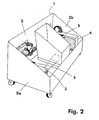
- the arrangement according to the invention substantially comprises a measuring unit 1 and an image and signal-processing unit 7.
- the measuring unit 1 is formed by a casing 2 which is adapted to the shape of a body part and in whose one side 2a is disposed a radiation source 3 for radiation at two energy levels and in whose other side 2b a radiation detector matrix 4 is disposed for detecting the radiation emitted from the radiation source 3.
- the radiation source 3 is preferably formed by an X-ray tube which can emit photons at two separate energy levels, for example 30 kV and 75 kV. These energy levels are used to determine the bone mineral content of the object to be measured 6 and it is therefore important that the energy levels are clearly separated and clearly defined.
- the different energy levels can, for example, be brought about by driving the X-ray tube 3 with a generator which can vary between energy levels.
- Another way of producing X-radiation at two energy levels is to filter the radiation obtained from an X-ray source 3 at one energy level.
- the radiation detector matrix 4 for detecting radiation is disposed in an opposite position relative to the radiation source 3.
- the detector matrix 4 comprises a number of elements which are arranged in matrix form and which can detect and quantify the radiation which impinges on each point at a given incidence or within a given time.
- the X-ray tube 3 and the detector matrix 4 can either be stationary or describe a linear movement over the object to be measured 6. In both cases a collimator is disposed connected to the X-ray tube 3, whereby the divergence of the X-rays can be delimited to cover the range of vision of the detector matrix 4.
- a specially arranged collimator is mounted in front of the detector matrix 4.
- the collimator is constructed such that it is perforated by apertures whose number equals that of the individual elements in the radiation detector matrix lying therebehind.
- the orientation on the apertures is such that they diverge from the focus of the radiation source and each aperture is oriented towards each of its points on the detector matrix.
- the purpose of the collimator is to filter out scattered secondary radiation which can cause interference, to operate such that the beams which pass through the apertures remain parallel, and to direct the transmitted radiation towards respective points on the detector matrix.
- the collimator can be made of material which has such high attenuation that only the beams which pass through the apertures are detected by the detector matrix 4 lying therebehind.
- the X-ray tube 3 is made to carry out a linear movement over the object to be measured 6
- the X-ray tube 3 is mounted on a mechanical arm. This arm moves in relation to the body part 6 to be measured such that the sections of the body part which are essential to the measurement are scanned
- the detector matrix 4 can comprise a single detector element.
- the measurement of the bone mineral content is carried out in a heel bone.
- the X-ray tube 3 is disposed so as to scan an area of approximately 10.0 x 15. 0 cm, i.e. equivalent to the total size of the heel bone.
- the X-ray tube 3 is directed towards the one side of the foot, towards or in the region of the heel part of the foot.
- the size of the region which the X-ray tube 3 scans obviously depends on the size of the body part 6 to be measured.
- the measuring unit further comprises a computer/amplifier 4a in order to quantify the radiation towards the detector matrix 4.
- the computer 4a is arranged such that it can identify at which point on the detector matrix 4 the radiation impinges and the photon energy level in the radiation. Since two "measuring windows" are used in the case of the energy levels characteristic of the two voltages generated, a more reliable result is obtained.
- the unit bearing reference sign 6 symbolizes the body part to be measured, such as a heel bone or a forearm, for example.
- the device is arranged for measuring the heel part of a foot.
- a third measuring parameter is required. This is obtained in that the distance measuring devices 5 are arranged on each side of the body part 6 to be measured and the distance from each side of the X-rayed object 6 can be determined by means of these devices 5. The thickness of the object can thus be calculated. These devices 5 are preferably made of laser measuring rings. In order that the position of the foot in the casing does not lead to unreliable measuring results, the distance-measuring devices 5 are arranged on each side of the foot.
- the method and arrangement according to the invention are based on the fact that, by means of the above-described X-radiation and measuring of the thickness of the object, three measurements can be provided which are different from one another and by means of which the proportion of bone mineral in a body part can be established.
- the object or body part to be measured substantially consists of three components: bone mineral (in the form of hydroxyapatite Ca 10 (PO 4 ) 6 (OH) 2 ), fat and water.
- bone mineral in the form of hydroxyapatite Ca 10 (PO 4 ) 6 (OH) 2
- fat in the form of hydroxyapatite Ca 10 (PO 4 ) 6 (OH) 2
- b hydroxyapatite Ca 10 (PO 4 ) 6 (OH) 2
- b hydroxyapatite Ca 10
- f hydroxyapatite Ca 10
- N 1 N 01 exp(- ⁇ b1 t b ⁇ b - ⁇ s1 t s ⁇ s - ⁇ f1 t f ⁇ f )
- N 2 N 02 exp(- ⁇ b2 t b ⁇ b - u s2 t s ⁇ s - u f2 t f ⁇ f )
- N i is the measured computing speed (i.e. the intensity) after passing through the object at energy level i; N 0i is the measured computing speed (ie the intensity) before passing through the object at energy level i; ⁇ xi is the mass attenuation coefficient (cm 2 /g) for the respective component; t x is the thickness (in cm) of the respective component and ⁇ x is the density of the respective component.
- the total thickness of the object is determined by means of distance-measuring devices on both sides of the object.
- T t b + t s + t f in which T represents the total thickness of the object and t b , t s and t f , respectively, represent the thickness of each component.
- the mass attenuation coefficients, the densities and thicknesses (t bk , t sk ) are known quantities.
- the thicknesses of the different components of the body part can therefore be calculated from the different equations for each element of the detector matrix.
- a representation of the bone mineral content of the body part to be measured can be produced from the result from each of these elements.
- an image and signal-processing unit 7 preferably a personal computer, is used.
- the measured quantitative values of the radiation at both photon energy levels are used to calculate the algorithms essential for assessing the result.
- the device also has access to databases containing standard values calculated from measured values from a large number of different specimens. The value measured by the measurement is compared with the value stored in the database in order to determine whether decalcification of the skeleton exists.
- the computer is equipped with software adapted to the object, whereby the combinations of information from the detector matrix and information from the distance-measuring devices are used such that all the components of the foot, fat, water and bone mineral, can be determined with a high degree of accuracy.
- a keyboard is used to communicate with the computer unit so that the operator can control the various possible operations.
- a screen on which images of the measured object can be displayed is preferably used for displaying the result.
- a printer can also be used to produce print-outs of the result obtained.
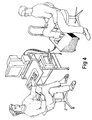
- Figures 2 and 3 show the most preferable embodiment of the arrangement according to the invention, which is an apparatus adapted for measuring a heel bone.
- the measuring apparatus can be constructed such that it is relatively small and simple so that the apparatus can be easily be moved for measuring different patients in different environments.
Landscapes
- Health & Medical Sciences (AREA)
- Life Sciences & Earth Sciences (AREA)
- Medical Informatics (AREA)
- Engineering & Computer Science (AREA)
- Heart & Thoracic Surgery (AREA)
- Animal Behavior & Ethology (AREA)
- Biophysics (AREA)
- Nuclear Medicine, Radiotherapy & Molecular Imaging (AREA)
- Optics & Photonics (AREA)
- Pathology (AREA)
- Radiology & Medical Imaging (AREA)
- Biomedical Technology (AREA)
- Physics & Mathematics (AREA)
- Molecular Biology (AREA)
- Surgery (AREA)
- High Energy & Nuclear Physics (AREA)
- General Health & Medical Sciences (AREA)
- Public Health (AREA)
- Veterinary Medicine (AREA)
- Orthopedic Medicine & Surgery (AREA)
- Dentistry (AREA)
- Oral & Maxillofacial Surgery (AREA)
- Apparatus For Radiation Diagnosis (AREA)
- Measurement Of The Respiration, Hearing Ability, Form, And Blood Characteristics Of Living Organisms (AREA)
- Analysing Materials By The Use Of Radiation (AREA)
Applications Claiming Priority (3)
| Application Number | Priority Date | Filing Date | Title |
|---|---|---|---|
| SE9500089 | 1995-01-12 | ||
| SE9500089A SE504929C2 (sv) | 1995-01-12 | 1995-01-12 | Metod och anordning för att mäta benmineralhalten i skelettet |
| PCT/SE1996/000008 WO1996021856A1 (en) | 1995-01-12 | 1996-01-10 | Method and device for measuring the content of bone mineral in the skeleton |
Publications (2)
| Publication Number | Publication Date |
|---|---|
| EP0803059A1 EP0803059A1 (en) | 1997-10-29 |
| EP0803059B1 true EP0803059B1 (en) | 2002-04-24 |
Family
ID=20396799
Family Applications (1)
| Application Number | Title | Priority Date | Filing Date |
|---|---|---|---|
| EP96900751A Expired - Lifetime EP0803059B1 (en) | 1995-01-12 | 1996-01-10 | Method and device for measuring the content of bone mineral in the skeleton |
Country Status (12)
| Country | Link |
|---|---|
| US (1) | US5809104A (zh) |
| EP (1) | EP0803059B1 (zh) |
| JP (1) | JP3787661B2 (zh) |
| KR (1) | KR100420582B1 (zh) |
| CN (1) | CN1102240C (zh) |
| AU (1) | AU693987B2 (zh) |
| CA (1) | CA2210250A1 (zh) |
| DE (1) | DE69620869T2 (zh) |
| DK (1) | DK0803059T3 (zh) |
| HK (1) | HK1005383A1 (zh) |
| SE (1) | SE504929C2 (zh) |
| WO (1) | WO1996021856A1 (zh) |
Families Citing this family (6)
| Publication number | Priority date | Publication date | Assignee | Title |
|---|---|---|---|---|
| US5748704A (en) * | 1997-03-10 | 1998-05-05 | Lunar Corporation | Peripheral bone densitometer |
| EP1459102A1 (en) * | 2001-12-05 | 2004-09-22 | Koninklijke Philips Electronics N.V. | Method to measure the entrance dose of a radiology apparatus |
| DE102004033989B4 (de) * | 2004-07-14 | 2015-08-13 | Siemens Aktiengesellschaft | Verfahren zur Messung der dreidimensionalen Dichteverteilung in Knochen |
| PL2343536T3 (pl) * | 2009-12-29 | 2019-01-31 | Mantex IP AB | Wykrywanie anomalii w materiale biologicznym |
| EP2372350B1 (en) * | 2010-01-28 | 2014-01-08 | Mantex AB | Method and apparatus for estimating the ash content of a biological material |
| DE102012217555A1 (de) * | 2012-09-27 | 2014-03-27 | Siemens Aktiengesellschaft | Verfahren und Computertomographie-System zur Ermittlung von Knochenmineraldichtewerten |
Family Cites Families (11)
| Publication number | Priority date | Publication date | Assignee | Title |
|---|---|---|---|---|
| DE2551584A1 (de) * | 1975-11-17 | 1977-05-26 | Siemens Ag | Roentgen-schichtgeraet zur herstellung von transversal-schichtbildern |
| US4768214A (en) * | 1985-01-16 | 1988-08-30 | American Science And Engineering, Inc. | Imaging |
| US4829549A (en) * | 1985-06-19 | 1989-05-09 | Vogel John M | Densitometer for scanning os calcis for predicting osteoporosis |
| WO1986007531A1 (en) * | 1985-06-19 | 1986-12-31 | Osteon Incorporated | Densitometer for scanning os calcis for predicting osteoporosis |
| US4663772A (en) * | 1985-09-30 | 1987-05-05 | Picker International, Inc. | Bone mineral analysis phantom |
| US4811373A (en) * | 1986-07-14 | 1989-03-07 | Hologic, Inc. | Bone densitometer |
| EP0432730B1 (en) * | 1989-12-14 | 1999-08-04 | Aloka Co. Ltd. | Bone mineral content measuring apparatus |
| JPH04332537A (ja) * | 1991-05-03 | 1992-11-19 | Horiba Ltd | 骨塩測定方法 |
| US5247559A (en) * | 1991-10-04 | 1993-09-21 | Matsushita Electric Industrial Co., Ltd. | Substance quantitative analysis method |
| EP0570936B1 (en) * | 1992-05-20 | 2000-08-09 | Aloka Co. Ltd. | Bone assessment apparatus |
| US5712892A (en) * | 1995-12-28 | 1998-01-27 | Eastman Kodak Company | Apparatus for measuring the bone mineral content of an extremity |
-
1995
- 1995-01-12 SE SE9500089A patent/SE504929C2/sv not_active IP Right Cessation
-
1996
- 1996-01-10 CN CN96191401A patent/CN1102240C/zh not_active Expired - Lifetime
- 1996-01-10 US US08/875,136 patent/US5809104A/en not_active Expired - Lifetime
- 1996-01-10 AU AU44615/96A patent/AU693987B2/en not_active Ceased
- 1996-01-10 DE DE69620869T patent/DE69620869T2/de not_active Expired - Lifetime
- 1996-01-10 EP EP96900751A patent/EP0803059B1/en not_active Expired - Lifetime
- 1996-01-10 JP JP52159896A patent/JP3787661B2/ja not_active Expired - Lifetime
- 1996-01-10 CA CA002210250A patent/CA2210250A1/en not_active Abandoned
- 1996-01-10 KR KR1019970704403A patent/KR100420582B1/ko not_active IP Right Cessation
- 1996-01-10 DK DK96900751T patent/DK0803059T3/da active
- 1996-01-10 WO PCT/SE1996/000008 patent/WO1996021856A1/en active IP Right Grant
-
1998
- 1998-05-27 HK HK98104565A patent/HK1005383A1/xx not_active IP Right Cessation
Also Published As
| Publication number | Publication date |
|---|---|
| SE9500089D0 (sv) | 1995-01-12 |
| CN1168174A (zh) | 1997-12-17 |
| KR100420582B1 (ko) | 2004-06-16 |
| WO1996021856A1 (en) | 1996-07-18 |
| EP0803059A1 (en) | 1997-10-29 |
| CN1102240C (zh) | 2003-02-26 |
| JP3787661B2 (ja) | 2006-06-21 |
| DE69620869T2 (de) | 2003-06-05 |
| CA2210250A1 (en) | 1996-07-18 |
| AU693987B2 (en) | 1998-07-09 |
| SE9500089L (sv) | 1996-07-13 |
| AU4461596A (en) | 1996-07-31 |
| HK1005383A1 (en) | 1999-01-08 |
| JPH10511882A (ja) | 1998-11-17 |
| SE504929C2 (sv) | 1997-05-26 |
| DK0803059T3 (da) | 2002-08-05 |
| US5809104A (en) | 1998-09-15 |
| DE69620869D1 (de) | 2002-05-29 |
Similar Documents
| Publication | Publication Date | Title |
|---|---|---|
| US6320931B1 (en) | Automated x-ray bone densitometer | |
| US4229651A (en) | Radiation scanning method and apparatus | |
| US4751722A (en) | X-ray apparatus | |
| EP2002287B1 (en) | Dynamic optimization of the signal-to-noise ratio of dual-energy attenuation data for reconstructing images | |
| US5841833A (en) | Dual-energy x-ray detector providing spatial and temporal interpolation | |
| US5841832A (en) | Dual-energy x-ray detector providing spatial and temporal interpolation | |
| US7697657B2 (en) | System and method of density and effective atomic number imaging | |
| US5987095A (en) | Method for detecting an image of an object | |
| EP2002397B1 (en) | Noise reduction in dual-energy x-ray imaging | |
| US20090080597A1 (en) | System and method for performing material decomposition using an overdetermined system of equations | |
| Towe et al. | X-ray backscatter imaging | |
| EP0123276B1 (en) | X-ray diagnostic apparatus | |
| WO2000015112A1 (en) | Reduced-angle mammography device and variants | |
| JPH0233975B2 (zh) | ||
| RU2711250C1 (ru) | Система кт-визуализации и способ для системы кт-визуализации | |
| EP0803059B1 (en) | Method and device for measuring the content of bone mineral in the skeleton | |
| Hounsfield | The EMI scanner | |
| CA2083064C (en) | X-ray backscatter detection system | |
| CA1164580A (en) | Compton scatter diagnostic apparatus for determining structures in a body | |
| US20020006181A1 (en) | Method and device for estimating bone mineral content of the calcaneus | |
| EP0041084A1 (en) | Radiation scanning method and apparatus | |
| WO2000021441A1 (en) | Method and device for measuring the bone mineral content of the skeleton | |
| McCULLOUGH et al. | Physical and dosimetric aspects of diagnostic geometrical and computer-assisted tomographic procedures | |
| JPH02500884A (ja) | 有機体における細胞変化を検査するための方法および装置 | |
| RU2173087C2 (ru) | Устройство для малоугловой маммографии (варианты) |
Legal Events
| Date | Code | Title | Description |
|---|---|---|---|
| PUAI | Public reference made under article 153(3) epc to a published international application that has entered the european phase |
Free format text: ORIGINAL CODE: 0009012 |
|
| 17P | Request for examination filed |
Effective date: 19970708 |
|
| AK | Designated contracting states |
Kind code of ref document: A1 Designated state(s): DE DK FR GB IT SE |
|
| RAP1 | Party data changed (applicant data changed or rights of an application transferred) |
Owner name: DEMETECH AB |
|
| RIN1 | Information on inventor provided before grant (corrected) |
Inventor name: KULLENBERG, RAGNAR Inventor name: ULLBERG, ANDERS |
|
| 17Q | First examination report despatched |
Effective date: 20000919 |
|
| GRAG | Despatch of communication of intention to grant |
Free format text: ORIGINAL CODE: EPIDOS AGRA |
|
| GRAG | Despatch of communication of intention to grant |
Free format text: ORIGINAL CODE: EPIDOS AGRA |
|
| GRAH | Despatch of communication of intention to grant a patent |
Free format text: ORIGINAL CODE: EPIDOS IGRA |
|
| GRAH | Despatch of communication of intention to grant a patent |
Free format text: ORIGINAL CODE: EPIDOS IGRA |
|
| REG | Reference to a national code |
Ref country code: GB Ref legal event code: IF02 |
|
| GRAA | (expected) grant |
Free format text: ORIGINAL CODE: 0009210 |
|
| AK | Designated contracting states |
Kind code of ref document: B1 Designated state(s): DE DK FR GB IT SE |
|
| REG | Reference to a national code |
Ref country code: GB Ref legal event code: FG4D |
|
| REF | Corresponds to: |
Ref document number: 69620869 Country of ref document: DE Date of ref document: 20020529 |
|
| REG | Reference to a national code |
Ref country code: DK Ref legal event code: T3 |
|
| ET | Fr: translation filed | ||
| PLBE | No opposition filed within time limit |
Free format text: ORIGINAL CODE: 0009261 |
|
| STAA | Information on the status of an ep patent application or granted ep patent |
Free format text: STATUS: NO OPPOSITION FILED WITHIN TIME LIMIT |
|
| 26N | No opposition filed |
Effective date: 20030127 |
|
| PGFP | Annual fee paid to national office [announced via postgrant information from national office to epo] |
Ref country code: DK Payment date: 20130121 Year of fee payment: 18 |
|
| REG | Reference to a national code |
Ref country code: DK Ref legal event code: EBP Effective date: 20140131 |
|
| PG25 | Lapsed in a contracting state [announced via postgrant information from national office to epo] |
Ref country code: DK Free format text: LAPSE BECAUSE OF NON-PAYMENT OF DUE FEES Effective date: 20140131 |
|
| REG | Reference to a national code |
Ref country code: FR Ref legal event code: PLFP Year of fee payment: 20 |
|
| PGFP | Annual fee paid to national office [announced via postgrant information from national office to epo] |
Ref country code: DE Payment date: 20150202 Year of fee payment: 20 Ref country code: IT Payment date: 20150130 Year of fee payment: 20 |
|
| PGFP | Annual fee paid to national office [announced via postgrant information from national office to epo] |
Ref country code: GB Payment date: 20150130 Year of fee payment: 20 Ref country code: FR Payment date: 20150202 Year of fee payment: 20 Ref country code: SE Payment date: 20150123 Year of fee payment: 20 |
|
| REG | Reference to a national code |
Ref country code: DE Ref legal event code: R071 Ref document number: 69620869 Country of ref document: DE |
|
| REG | Reference to a national code |
Ref country code: GB Ref legal event code: PE20 Expiry date: 20160109 |
|
| REG | Reference to a national code |
Ref country code: SE Ref legal event code: EUG |
|
| PG25 | Lapsed in a contracting state [announced via postgrant information from national office to epo] |
Ref country code: GB Free format text: LAPSE BECAUSE OF EXPIRATION OF PROTECTION Effective date: 20160109 |