EP0802774B1 - Third molar eruption predictor - Google Patents
Third molar eruption predictor Download PDFInfo
- Publication number
- EP0802774B1 EP0802774B1 EP96900614A EP96900614A EP0802774B1 EP 0802774 B1 EP0802774 B1 EP 0802774B1 EP 96900614 A EP96900614 A EP 96900614A EP 96900614 A EP96900614 A EP 96900614A EP 0802774 B1 EP0802774 B1 EP 0802774B1
- Authority
- EP
- European Patent Office
- Prior art keywords
- line
- intersection
- eruption
- point
- molar
- Prior art date
- Legal status (The legal status is an assumption and is not a legal conclusion. Google has not performed a legal analysis and makes no representation as to the accuracy of the status listed.)
- Expired - Lifetime
Links
- 210000004357 third molar Anatomy 0.000 title claims description 31
- 230000001174 ascending effect Effects 0.000 claims abstract description 23
- 210000004373 mandible Anatomy 0.000 claims abstract description 16
- 238000000034 method Methods 0.000 claims abstract description 15
- 239000000463 material Substances 0.000 abstract description 8
- 238000005259 measurement Methods 0.000 abstract description 7
- 238000010586 diagram Methods 0.000 description 4
- 238000000605 extraction Methods 0.000 description 2
- 239000007787 solid Substances 0.000 description 2
- 238000001356 surgical procedure Methods 0.000 description 2
- 238000012360 testing method Methods 0.000 description 2
- 208000003941 Impacted Tooth Diseases 0.000 description 1
- 238000000692 Student's t-test Methods 0.000 description 1
- 210000000988 bone and bone Anatomy 0.000 description 1
- 230000035945 sensitivity Effects 0.000 description 1
- 238000012353 t test Methods 0.000 description 1
- 238000005303 weighing Methods 0.000 description 1
Images


Classifications
-
- A—HUMAN NECESSITIES
- A61—MEDICAL OR VETERINARY SCIENCE; HYGIENE
- A61C—DENTISTRY; APPARATUS OR METHODS FOR ORAL OR DENTAL HYGIENE
- A61C19/00—Dental auxiliary appliances
- A61C19/04—Measuring instruments specially adapted for dentistry
Definitions
- the present invention relates to the field of dentistry and specifically to materials and methods for the prediction of eruption or impaction of molars.
- the present invention provides a safe, reliable means for predicting the course of development of the lower third molar. Methods and materials according to the invention also eliminate the need for elaborate cephalographic measurements.
- the present invention provides materials and methods for predicting the developmental course of teeth.
- materials and methods according to the invention allow one to predict whether a lower third molar (wisdom tooth) will erupt or remain impacted.
- methods comprising the steps of obtaining an X-ray, and preferably a panoramic tomogram, of a patient's mandibular region; superimposing over said X-ray or panoramic tomogram a sheet, which may be transparent, having a first line and a second line perpendicular to said first line and positioned with respect to the X-ray or tomogram such that said first line is coincident along a superior aspect of an occlusal surface of the first and/or second molars and said second line is tangential to a distal surface of said second molar; and determining a point of intersection of said first line and an anterior border of the ascending ramus of the mandible of said patient.
- the distance between the intersection of the first line with the anterior border of the ascending ramus of the mandible and the intersection of the first line with the second line provides a basis for predicting whether the third molar will remain impacted or will erupt. If that distance is 9.5 mm or less, there is an approximately 100% probability that the tooth will remain impacted. If the distance is 16.5 mm or greater, there is an approximately 100% probability that the tooth will erupt.
- the sheet may contain reference points which demarcate critical points (9.5 mm and 16.5 mm) against which intersection of the anterior aspect of the ascending ramus of the mandible with the first line is measured.
- the practioner may visually determine the position of intersection of the ramus with the first line in comparison to the reference points in order to diagnose whether impaction or eruption will take place. For example, if the intersection of the ascending ramus of the mandible and the first line on the sheet is at or mesial to the intersection of a first reference point spaced about 9.5 mm from the intersection of the first and second lines, then it is predicted that the tooth will remain impacted.
- a reference line or point may be drawn at approximately 16.5 mm from the intersection of the first and second lines and eruption may be predicted based upon intersection of the anterior aspect of the ascending ramus of the mandible with the first line at a point at or distal to the 16.5 mm reference point.
- the reference points are positioned along the first line and may intersect the first line, but it is not necessary that they do so, as the reference points may be lines which terminate above the first line. In the latter case, the reference line may be visually extended to the first line for demarcation of critical areas.
- Materials according to the invention comprise a sheet having a first line and a second line perpendicular to a point on the first line.
- the sheet comprises at least one and may optionally include two or three reference points positioned such that a first reference point is spaced about 9.5 mm from the intersection of the first and second lines.
- a second reference point is positioned approximately 14.5 mm from the intersection of the first and second lines, and a third reference point is positioned at approximately 16.5 mm from the intersection of the first and second lines.
- the present invention provides materials and methods for use in predicting whether a patient's third molar will eventually erupt or remain impacted. Consideration of the methods described herein reveals that such methods may be adapted to the prediction of eruption/impaction of other teeth by simply altering the critical distances on the transparent sheet described herein.
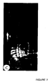
- a device is shown in Figure 3 superimposed over a schematic diagram of a mandible.
- the device is a sheet having thereon a first line and a second line which is perpendicular to the first line, and optionally three reference points.
- the first reference point shown as line A in Figure 3 (long dashes) is positioned along the first line at approximately 9.5 mm from the intersection of the first and second lines.
- the second reference point shown as line B in Figure 3 (short dashes), intersects the first line at a point approximately 16.5 mm from the intersection of the first and second lines.
- a third reference point, shown as line C in Figure 3 solid line between the two broken lines) represents the cut-off point for predicting eruption/impaction.
- FIG. 4 represents a device according to the invention superimposed upon a tomogram showing an ascending ramus of the mandible.
- Figure 5 shows a diagram of a device according to the invention with reference points at 9.5 mm, 14.5 mm, and 16.5 mm. The only critical position is the point of intersection with the first line of the device.
- the device shown in Figures 3, 4, and 5 is superimposed over a panoramic tomogram of the mandibular region, including the region of the molars.
- the device is placed on the tomogram such that the first line coincides with the superior (occlusal) surface of the first and second molars and the second, perpendicular line coincides with the distal surface of the second molar.
- Figure 4 shows proper placement of the device over a tomogram or X-ray.
- the clinician may either measure the distance from the point of intersection of the first and second lines to the anterior aspect of the ascending ramus or the aforementioned reference points may be used to predict the developmental fate of the lower third molar.
- Intersection of the first line with the anterior aspect of the ascending ramus mesial to line A in Figure 3 constitutes an approximately 100% probability that the third molar will remain impacted.
- Intersection distal to line B in Figure 3 results in an approximately 100% probability of eruption of the third molar.
- Intersection between lines A and C in Figure 3 results in a high probability of continued impaction and intersection between lines C and B indicates a high probability of eruption as discussed below.
- Figures 6 and 7 are panoramic tomograms which show lower third molars predicted to erupt and to be impacted, respectively, according to the invention.
- the result of the invention is that the practitioner may advise patients whether to seek removal of the third molar at an age where such surgery is relatively less risky as compared to performing the surgery at a later age. Accordingly, use of claimed materials and methods on individuals in their late teens or early twenties is preferred.
- a priori probabilities for eruption and impaction of lower third molars are 30% and 70%, respectively. Because impaction is more common than eruption, the cutoff for predicting impaction or eruption may be more distal from the distal surface of the second molar than would be predicted by straightforward probability analysis. Accordingly, a weighted decision point may be obtained, as shown in Figure 2, by weighing the values in Figure 1 by their respective a priori probabilities (30% and 70%). When this is done, a new cutoff point is generated 14.5 mm from the point of intersection of the first and second lines based upon the fact that the sum of false negatives and false positives in the weighted histogram of Figure 2 is lowest at a point 14.5 mm from the distal surface of the second molar as shown below in Table 1.
- the device shown in Figure 3 was applied to each tomogram as a transparent sheet superimposed upon the tomogram, wherein the cutoff point (line C in Figure 3) for predicting eruption/impaction was 14.5 mm. If the first line intersects the anterior aspect of the ascending ramus of the mandible at or mesial to a distance of 9.5 mm (line A in Figure 3) there was a 100% probability that the tooth would remain impacted. If the intersection of the first line and the anterior aspect of the ascending ramus was distal to 16.5 mm from the second line there was a 100% probability of eruption.
- the mean values of the distance from the intersection of the first and second (perpendicular) lines to the anterior aspect of the ascending ramus were 11.1 mm (s.d. 2.7) for impacted third molars and 13.6 mm (s.d. 2.0) for erupted third molars.
- use of the device shown in Figure 3 resulted in 97% predictability in the longitudinal study referred to above. Only one exceptionally small tooth in a male patient in the study failed to meet the predicted outcome (the tooth erupted when use of the device predicted impaction).
Landscapes
- Health & Medical Sciences (AREA)
- Life Sciences & Earth Sciences (AREA)
- Animal Behavior & Ethology (AREA)
- General Health & Medical Sciences (AREA)
- Biophysics (AREA)
- Oral & Maxillofacial Surgery (AREA)
- Dentistry (AREA)
- Epidemiology (AREA)
- Engineering & Computer Science (AREA)
- Biomedical Technology (AREA)
- Public Health (AREA)
- Veterinary Medicine (AREA)
- Eye Examination Apparatus (AREA)
- Dental Tools And Instruments Or Auxiliary Dental Instruments (AREA)
- Measuring And Recording Apparatus For Diagnosis (AREA)
- Steroid Compounds (AREA)
- Steering Control In Accordance With Driving Conditions (AREA)
Abstract
Description
| Variables calculated from weighted histograms (in percent). | |||
| 13.5 mm | 14.5 mm | 15.5 mm | |
| False negatives + false positives | 31 | 25 | 26 |
| Sensitivity | 80 | 95 | 95 |
| Specificity | 45 | 30 | 25 |
| Probability of eruption | 49 | 72 | 68 |
| Probability of impaction | 77 | 76 | 75 |
Claims (6)
- A device for predicting eruption of third molar teeth, comprising a sheet having affixed thereon a first line, a second line perpendicular to said first line, and a first reference point positioned along said first line and spaced about 14.5 mm from said second line.
- The device according to claim 1, further comprising a second reference point positioned along said first line and spaced about 9.5 mm from said second line and a third reference point along said first line spaced about 16.5 mm from said second line.
- The device according to claim 1, wherein said sheet is transparent.
- A method for predicting eruption of lower third molar teeth in a patient, comprising the steps of:obtaining a panoramic tomogram of said patient's mandibular region, including the region of the second, and third molars;superimposing over said panoramic tomogram a sheet having affixed thereon a first line, a second line perpendicular to said first line and a first reference point positioned along said first line and spaced about 14.5 mm from said second line such that said first line is coincident along a superior aspect of an occlusal surface of said first and second molars and said second line is tangential to a distal surface of said second molar;determining a point of intersection of said first line and an anterior border of the ascending ramus of the mandible of said patient; andmeasuring a distance from said point of intersection of said first line and an anterior border of the ascending ramus of the mandible of said patient to the point of intersection of said first and second lines on said sheet, wherein said measuring step comprises the step of comparing the intersection of the anterior aspect of the ascending ramus of the mandible with said first line with said reference point on said sheet.
- The method according to claim 4, wherein said sheet is transparent.
- The method according to claim 4, wherein second and third reference points are positioned at approximately 9.5 mm and 16.5 mm, respectively from a point of intersection between said first line and said second line.
Applications Claiming Priority (3)
| Application Number | Priority Date | Filing Date | Title |
|---|---|---|---|
| US08/372,041 US5816814A (en) | 1995-01-12 | 1995-01-12 | Third molar eruption predictor and method of use |
| US372041 | 1995-01-12 | ||
| PCT/FI1996/000022 WO1996021402A1 (en) | 1995-01-12 | 1996-01-10 | Third molar eruption predictor |
Publications (2)
| Publication Number | Publication Date |
|---|---|
| EP0802774A1 EP0802774A1 (en) | 1997-10-29 |
| EP0802774B1 true EP0802774B1 (en) | 1999-04-07 |
Family
ID=23466456
Family Applications (1)
| Application Number | Title | Priority Date | Filing Date |
|---|---|---|---|
| EP96900614A Expired - Lifetime EP0802774B1 (en) | 1995-01-12 | 1996-01-10 | Third molar eruption predictor |
Country Status (7)
| Country | Link |
|---|---|
| US (1) | US5816814A (en) |
| EP (1) | EP0802774B1 (en) |
| AT (1) | ATE178474T1 (en) |
| AU (1) | AU4439596A (en) |
| CA (1) | CA2209668A1 (en) |
| DE (1) | DE69602006D1 (en) |
| WO (1) | WO1996021402A1 (en) |
Families Citing this family (10)
| Publication number | Priority date | Publication date | Assignee | Title |
|---|---|---|---|---|
| US6312458B1 (en) | 2000-01-19 | 2001-11-06 | Scimed Life Systems, Inc. | Tubular structure/stent/stent securement member |
| DE10044736C2 (en) * | 2000-09-09 | 2002-10-10 | Marcus Oliver Ahlers | Length measuring instrument for assessing clinical functional findings of the chewing organ |
| US10022202B2 (en) | 2013-03-15 | 2018-07-17 | Triagenics, Llc | Therapeutic tooth bud ablation |
| AU2010247874B2 (en) * | 2009-05-11 | 2015-05-14 | TriAgenics, Inc. | Therapeutic tooth bud ablation |
| US12514679B2 (en) | 2009-05-11 | 2026-01-06 | TriAgenics, Inc. | Therapeutic tooth bud ablation |
| WO2014143014A1 (en) * | 2013-03-15 | 2014-09-18 | Triagenics, Llc | Therapeutic tooth bud ablation |
| US9438264B1 (en) | 2015-09-10 | 2016-09-06 | Realtek Semiconductor Corp. | High-speed capacitive digital-to-analog converter and method thereof |
| AU2020287387B2 (en) | 2019-06-06 | 2024-02-01 | TriAgenics, Inc. | Ablation probe systems |
| EP4470491A3 (en) | 2020-10-26 | 2025-01-22 | TriAgenics, Inc. | Ablation probe systems |
| EP4646169A2 (en) * | 2023-01-04 | 2025-11-12 | Align Technology, Inc. | Methods and apparatuses including tooth eruption prediction |
Family Cites Families (11)
| Publication number | Priority date | Publication date | Assignee | Title |
|---|---|---|---|---|
| US1790572A (en) * | 1931-01-27 | Lens in | ||
| US2693035A (en) * | 1952-06-17 | 1954-11-02 | Hope G Beck | Template adapted for the use of typists |
| US3299557A (en) * | 1965-01-06 | 1967-01-24 | Nat Blank Book Co | Projection transparencies |
| US3878611A (en) * | 1973-11-08 | 1975-04-22 | Benjamin C Seaman | Denture measurement means |
| US4131998A (en) * | 1977-03-09 | 1979-01-02 | Spears Colin P | Tumor growth measurement device |
| US4738619A (en) * | 1986-11-25 | 1988-04-19 | Ross Systems Corporation | Methods and apparatus for selecting a dental anchor |
| US4884345A (en) * | 1988-05-12 | 1989-12-05 | Siemens-Pacesetter, Inc. | Adjustable template for pacemaker ECG analysis and method of use |
| US4986005A (en) * | 1989-08-07 | 1991-01-22 | Grippi Christopher P | Pleat pattern layout assembly and method |
| CN1045464A (en) * | 1990-02-17 | 1990-09-19 | 平顶山市专利技术开发部 | Multifunctional pocket search card of cardioelectric and cardiac function data |
| US5318441A (en) * | 1992-09-17 | 1994-06-07 | Keller Duane C | Method of cephalometric evaluation of dental radiographs |
| CN1076603A (en) * | 1993-02-17 | 1993-09-29 | 黄宗之 | Examination ruler for physique development of children |
-
1995
- 1995-01-12 US US08/372,041 patent/US5816814A/en not_active Expired - Fee Related
-
1996
- 1996-01-10 DE DE69602006T patent/DE69602006D1/en not_active Expired - Lifetime
- 1996-01-10 WO PCT/FI1996/000022 patent/WO1996021402A1/en not_active Ceased
- 1996-01-10 AT AT96900614T patent/ATE178474T1/en active
- 1996-01-10 EP EP96900614A patent/EP0802774B1/en not_active Expired - Lifetime
- 1996-01-10 CA CA002209668A patent/CA2209668A1/en not_active Abandoned
- 1996-01-10 AU AU44395/96A patent/AU4439596A/en not_active Abandoned
Also Published As
| Publication number | Publication date |
|---|---|
| WO1996021402A1 (en) | 1996-07-18 |
| AU4439596A (en) | 1996-07-31 |
| CA2209668A1 (en) | 1996-07-18 |
| EP0802774A1 (en) | 1997-10-29 |
| DE69602006D1 (en) | 1999-05-12 |
| ATE178474T1 (en) | 1999-04-15 |
| US5816814A (en) | 1998-10-06 |
Similar Documents
| Publication | Publication Date | Title |
|---|---|---|
| Benn | A review of the reliability of radiographic measurements in estimating alveolar bone changes | |
| Canullo et al. | Distinguishing predictive profiles for patient‐based risk assessment and diagnostics of plaque induced, surgically and prosthetically triggered peri‐implantitis | |
| Güler et al. | The evaluation of vertical heights of maxillary and mandibular bones and the location of anatomic landmarks in panoramic radiographs of edentulous patients for implant dentistry | |
| Bell et al. | The accuracy of dental panoramic tomographs in determining the root morphology of mandibular third molar teeth before surgery | |
| Low et al. | Comparison of periapical radiography and limited cone-beam tomography in posterior maxillary teeth referred for apical surgery | |
| Verstraete et al. | Diagnostic value of full-mouth radiography in dogs | |
| Kim et al. | When is cone‐beam computed tomography imaging appropriate for diagnostic inquiry in the management of inflammatory periodontitis? An American Academy of Periodontology best evidence review | |
| Jeffcoat et al. | Digital subtraction radiography for longitudinal assessment of peri-implant bone change: method and validation | |
| Bondemark et al. | Incidental findings of pathology and abnormality in pretreatment orthodontic panoramic radiographs | |
| Miloro et al. | Radiographic proximity of the mandibular third molar to the inferior alveolar canal | |
| Olive et al. | Reliability and validity of lower third molar space-assessment techniques | |
| Ventä et al. | A device to predict lower third molar eruption | |
| Ventä | Predictive model for impaction of lower third molars | |
| Zaki et al. | Is radiologic assessment of alveolar crest height useful to monitor periodontal disease activity? | |
| Chow et al. | Bone stability around implants in elderly patients with reduced bone mineral density–a prospective study on mandibular overdentures | |
| Firestone et al. | The effect of a knowledge-based, image analysis and clinical decision support system on observer performance in the diagnosis of approximal caries from radiographic images | |
| Mohan et al. | Diagnostic accuracy of CBCT for aggressive periodontitis | |
| Mohammed et al. | Localization of impacted canines-a comparative study of computed tomography and orthopantomography | |
| EP0802774B1 (en) | Third molar eruption predictor | |
| El et al. | Strategies for managing the risk of mucogingival changes during impacted maxillary canine treatment | |
| Battagel | Discriminant analysis: a model for the prediction of relapse in Class III children treated orthodontically by a non-extraction technique | |
| Rauf et al. | Pattern of mandibular third molar impaction: a radiographic study | |
| Luciani et al. | DIAGNOSIS AND TREATMENT PLANNING IN ORAL SURGERY USING CONE BEAM COMPUTED TOMOGRAPHY (CBCT): A NARRATIVE REVIEW. | |
| Dwivedi et al. | Correlation between Radiomorphometric indices and edentulous mandibular arches to diagnose osteoporosis using orthopantomogram in West Bengal state in India | |
| Al-Rasheed | Assessing peculiarity of molar root trunk dimensions in a sample of Saudi population–A radiographic analysis |
Legal Events
| Date | Code | Title | Description |
|---|---|---|---|
| PUAI | Public reference made under article 153(3) epc to a published international application that has entered the european phase |
Free format text: ORIGINAL CODE: 0009012 |
|
| 17P | Request for examination filed |
Effective date: 19970718 |
|
| AK | Designated contracting states |
Kind code of ref document: A1 Designated state(s): AT BE CH DE DK FR GB IE LI NL SE |
|
| 17Q | First examination report despatched |
Effective date: 19971023 |
|
| GRAG | Despatch of communication of intention to grant |
Free format text: ORIGINAL CODE: EPIDOS AGRA |
|
| GRAG | Despatch of communication of intention to grant |
Free format text: ORIGINAL CODE: EPIDOS AGRA |
|
| GRAG | Despatch of communication of intention to grant |
Free format text: ORIGINAL CODE: EPIDOS AGRA |
|
| GRAH | Despatch of communication of intention to grant a patent |
Free format text: ORIGINAL CODE: EPIDOS IGRA |
|
| GRAH | Despatch of communication of intention to grant a patent |
Free format text: ORIGINAL CODE: EPIDOS IGRA |
|
| GRAA | (expected) grant |
Free format text: ORIGINAL CODE: 0009210 |
|
| AK | Designated contracting states |
Kind code of ref document: B1 Designated state(s): AT BE CH DE DK FR GB IE LI NL SE |
|
| PG25 | Lapsed in a contracting state [announced via postgrant information from national office to epo] |
Ref country code: SE Free format text: THE PATENT HAS BEEN ANNULLED BY A DECISION OF A NATIONAL AUTHORITY Effective date: 19990407 Ref country code: NL Free format text: LAPSE BECAUSE OF FAILURE TO SUBMIT A TRANSLATION OF THE DESCRIPTION OR TO PAY THE FEE WITHIN THE PRESCRIBED TIME-LIMIT Effective date: 19990407 Ref country code: LI Free format text: LAPSE BECAUSE OF FAILURE TO SUBMIT A TRANSLATION OF THE DESCRIPTION OR TO PAY THE FEE WITHIN THE PRESCRIBED TIME-LIMIT Effective date: 19990407 Ref country code: FR Free format text: LAPSE BECAUSE OF FAILURE TO SUBMIT A TRANSLATION OF THE DESCRIPTION OR TO PAY THE FEE WITHIN THE PRESCRIBED TIME-LIMIT Effective date: 19990407 Ref country code: CH Free format text: LAPSE BECAUSE OF FAILURE TO SUBMIT A TRANSLATION OF THE DESCRIPTION OR TO PAY THE FEE WITHIN THE PRESCRIBED TIME-LIMIT Effective date: 19990407 Ref country code: BE Free format text: LAPSE BECAUSE OF FAILURE TO SUBMIT A TRANSLATION OF THE DESCRIPTION OR TO PAY THE FEE WITHIN THE PRESCRIBED TIME-LIMIT Effective date: 19990407 Ref country code: AT Free format text: LAPSE BECAUSE OF FAILURE TO SUBMIT A TRANSLATION OF THE DESCRIPTION OR TO PAY THE FEE WITHIN THE PRESCRIBED TIME-LIMIT Effective date: 19990407 |
|
| REF | Corresponds to: |
Ref document number: 178474 Country of ref document: AT Date of ref document: 19990415 Kind code of ref document: T |
|
| REG | Reference to a national code |
Ref country code: CH Ref legal event code: EP |
|
| REG | Reference to a national code |
Ref country code: IE Ref legal event code: FG4D |
|
| REF | Corresponds to: |
Ref document number: 69602006 Country of ref document: DE Date of ref document: 19990512 |
|
| PG25 | Lapsed in a contracting state [announced via postgrant information from national office to epo] |
Ref country code: DK Free format text: LAPSE BECAUSE OF FAILURE TO SUBMIT A TRANSLATION OF THE DESCRIPTION OR TO PAY THE FEE WITHIN THE PRESCRIBED TIME-LIMIT Effective date: 19990707 |
|
| PG25 | Lapsed in a contracting state [announced via postgrant information from national office to epo] |
Ref country code: DE Free format text: LAPSE BECAUSE OF FAILURE TO SUBMIT A TRANSLATION OF THE DESCRIPTION OR TO PAY THE FEE WITHIN THE PRESCRIBED TIME-LIMIT Effective date: 19990708 |
|
| NLV1 | Nl: lapsed or annulled due to failure to fulfill the requirements of art. 29p and 29m of the patents act | ||
| EN | Fr: translation not filed | ||
| REG | Reference to a national code |
Ref country code: CH Ref legal event code: PL |
|
| PG25 | Lapsed in a contracting state [announced via postgrant information from national office to epo] |
Ref country code: IE Free format text: LAPSE BECAUSE OF NON-PAYMENT OF DUE FEES Effective date: 20000110 Ref country code: GB Free format text: LAPSE BECAUSE OF NON-PAYMENT OF DUE FEES Effective date: 20000110 |
|
| PLBE | No opposition filed within time limit |
Free format text: ORIGINAL CODE: 0009261 |
|
| STAA | Information on the status of an ep patent application or granted ep patent |
Free format text: STATUS: NO OPPOSITION FILED WITHIN TIME LIMIT |
|
| 26N | No opposition filed | ||
| GBPC | Gb: european patent ceased through non-payment of renewal fee |
Effective date: 20000110 |
|
| REG | Reference to a national code |
Ref country code: IE Ref legal event code: MM4A |