EP0802736B1 - Machine for cutting away undesired tissue from e.g. fish fillets - Google Patents
Machine for cutting away undesired tissue from e.g. fish fillets Download PDFInfo
- Publication number
- EP0802736B1 EP0802736B1 EP95939432A EP95939432A EP0802736B1 EP 0802736 B1 EP0802736 B1 EP 0802736B1 EP 95939432 A EP95939432 A EP 95939432A EP 95939432 A EP95939432 A EP 95939432A EP 0802736 B1 EP0802736 B1 EP 0802736B1
- Authority
- EP
- European Patent Office
- Prior art keywords
- machine
- drum
- freezing
- fillets
- fillet
- Prior art date
- Legal status (The legal status is an assumption and is not a legal conclusion. Google has not performed a legal analysis and makes no representation as to the accuracy of the status listed.)
- Expired - Lifetime
Links
Images


Classifications
-
- A—HUMAN NECESSITIES
- A22—BUTCHERING; MEAT TREATMENT; PROCESSING POULTRY OR FISH
- A22C—PROCESSING MEAT, POULTRY, OR FISH
- A22C25/00—Processing fish ; Curing of fish; Stunning of fish by electric current; Investigating fish by optical means
- A22C25/16—Removing fish-bones; Filleting fish
Definitions
- the present invention relates to a machine for cutting away undesired tissue, e.g. fat tissue, fatty tissue, tissue exhibiting an undesired colour and, generally, any undesired tissue from fillets/pieces of meat, e.g. fish fillets.
- undesired tissue e.g. fat tissue, fatty tissue, tissue exhibiting an undesired colour and, generally, any undesired tissue from fillets/pieces of meat, e.g. fish fillets.
- the invention relates to cutting away fat and dark meat in the form of fat tissue from fish fillets, where such fat tissue, in addition to just beneath the skin, extends in the longitudinal direction of the fillets approximately in the middle of each fillet/fish side piece, exhibiting an approximately triangular cross-section.
- the object of the invention is to provide an efficient machine for cutting away undesired tissue, e.g. fat tissue, fatty tissue, tissue having an undesired colour and, generally, any kind of undesired tissue from fillets/pieces of meat, e.g. fish fillets.
- undesired tissue e.g. fat tissue, fatty tissue, tissue having an undesired colour and, generally, any kind of undesired tissue from fillets/pieces of meat, e.g. fish fillets.
- the fillets with the skins on are supplied to the freezing drum lying on a conveyor, the tensioning thereof within the fillet delivery area adjacent the freezing drum being adjusted according to problemfree delivery of the fillets, the longitudinal direction thereof extending in the circumferential and rotational direction of the freezing drum.
- the removal of said dark fat tissue portions of fish fillets and fillets of animal meat shall be implemented by means of such a freezing drum known per se as well as a supply conveyor assigned thereto.
- a freezing drum known per se as well as a supply conveyor assigned thereto.
- the fillets may also be divided as known per se along one or more planes parallel to the two opposite main faces of the fillets.
- a machine for cutting away undesired fat tissue portions is adapted to treat fillets where undesired fat tissue portion substantially extends in one main direction (in the longitudinal direction of fish), so that the undesired fat tissue portion upon the freezing of the fillet on the rotary drum will extend substantially in the circumferential direction thereof.
- a machine for cutting away undesired fat tissue portion comprises i.a. a rotary freezing drum, a supply conveyor for fillets being assigned thereto, the freezing drum being formed with at least one circumferential groove adapted to accommodate a fat tissue portion pressed into the same.
- the undesired longitudinal fat tissue portion of the fillet When a fillet is fed towards the rotary freezing drum, the undesired longitudinal fat tissue portion of the fillet will land in the outer opening portion of the circumferential groove and be pressed into the latter. Within the groove, the fat tissue portion freezes so that it is anchored thereto (and so does the skin resting against the drum face if a skinning of fish fillets is performed simultaneously).
- the rotary band knife cuts loose and separates the skinned (skinfree), fat tissue-free fillet, fat tissue and skin frozen firmly to the freezing drum being removed from the drum through a scraping operation as known per se by means of scraper means.
- the supply conveyor preferably consisting of parallel single threads, has a controllable tensioning in order to be adjusted to the desired degree of pressing-in (of the tissue into said groove) and the pressing force which, in other respects, acts on the fillet.
- a groove cross-section formed into the freezing drum may be adjusted to receive mutually differing fat tissue portion sizes.
- the conveyor positioned below the drum pressing the entire fat tissue portion into the groove, filling the latter only partly, a larger fillet having a more comprehensive fat tissue portion needing an increase in the upwardly directed pressure from the conveyor against the fillet on the freezing drum, so that all of the larger fat tissue portion is pressed into the groove, more or less filling the same.
- the freezing drum may be assigned rotary scraper means known per se, e.g. one means scraping the drum mantle face free of skin and one means scraping within said groove to clean it.
- one or more scraper means may be shaped and designed for scraping both along the drum mantle face and within said groove.
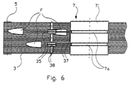
- reference numeral 1 denotes the machine frame, at one end thereof is mounted a supply chute 2 for supplying fish fillets F to an endless conveyor 3 extending in the longitudinal direction 4 of the machine, corresponding to the feed direction for the filets, the conveyor 3 passing around a turning roller 5 at the upstream end of the machine and a combined turning and drive roller 6 at the downstream and outlet end of the machine (feed-out end for treated fillets FS).
- the conveyor 3 may be built up and supported in various ways.
- One suitable conveyor structure consists in accordance with figures 2 and 4 of single threads, cords or strings 3a which, easier than a coherent band or tape, can adapt itself to the shape of the fillet F, the skin and fat tissue portion VP of which one desires to remove.
- the fat tissue portion may have varying cross-sectional shape, but in fat fish of all kinds said portion has a substantially triangular cross-section, where one of the sides of the triangle extends adjacent the inner side av the skin S .
- the mantle face of the freezing drum 7 is denoted at 7' and the freezing aggregate thereof at 8.
- a gear motor 9 mounted on the machine frame 1, serves to drive both the freezing drum 7 and the conveyor 3.
- a first chain 10 has been passed around a chain wheel 11 on the outgoing shaft of the gear motor 9 and around a chain wheel 12 on a drive grommet on the freezing drum 7, while a second chain 13 has been passed partly around a chain wheel 14 on the turning and driving roller 6 for the conveyor 3, partly around a freely rotatably supported chain wheel 15 driven by the first chain 10.
- Reference numeral 16 denotes a tensioning chain wheel.
- the rotational direction 17 of the freezing drum 7 is anti-clockwise.
- the fish fillets F to be treated within the machine are supplied on the conveyor 3, skin side facing upwards.
- the freezing drum 7 works according to a principle known per se in fish treatment generally, namely that a moist fillet F at the skin side is frozen to the mantle face 7' of the freezing drum 7, where the fillet is hold firmly through the ice formed while it is moved towards and past a cutting tool, e.g. in the form of a driven, endless band knife 18 of a design known per se.
- Two rotatable scraper means are denoted at 19, 20. They serve to scrape off fish skin and fat tissue frozen to the drum 7.
- the conveyor 3 has, partly due to its design, shape and inherent material properties, partly due to the way it is supported, a certain elastic resilience,
- the upper part of the conveyor passes through a longitudinal deflection distance.
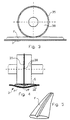
- Support rollers 21, 22, 22' and 23 define the deflection portion 3' of the upper part of the conveyor 3.
- the support rollers 22, 22' may be constituted by three independent rollers or by a graduated roller having a central portion 22 having the largest diameter and two outer portions 22' having a smaller diameter.
- the fat tissue portion VP of this fillet F is supported by means of the conveyor cords 3a which are supported by the roller portion 22 having the largest diameter.
- the central portion of the fillet, including the fat tissue portion VP is supported by the conveyor cords 3a positioned at a higher level than the conveyor cords 3a supporting the outer fillet portions.
- one of these support rollers namely the graduated roller 22,22' and/or the roller 23; possibly two side rollers 22', one central roller 22 and/or the roller 23 can be controllable at least in the vertical direction.
- a displaceable press roller 24 has been-disposed in the examplary embodiment in lieu of the previously mentioned support roller 22, figure 2.
- the press roller 24 is mounted on one end of a spring-loaded (25) angular rod 26 adapted to rotate about the same shaft on which the support roller 21 is mounted.
- the invention aims at providing a machine for simple and efficient cutting away said longitudinal fat tissue portion VP from fillets.
- This is realized by providing the freezing drum 7 with at least one circumferential groove 7a, into which the fat tissue portion VP is pressed by the pressing effect exerted from below/upwardly on the fillet by the conveyor 3 due to shape, design, material properties, support and tensioning of the latter, possibly by further help from a press roller 24, causing the fat tissue portion VP to be pressed into the circumferential groove prior to the cutting process proper taking place.
- the fat tissue portion VP within the freezing drum groove 7a is frozen firmly to the groove-defining wall faces within the groove, thus being fixed and retained prior to the following cutting operation, which is performed by the cutting edge of the band knife 18, cutting the fillet F free, separating it from skin and fat tissue portion, skin S and fat tissue VP still being frozen to the freezing drum until these waste products are removed by means of the scraper means 19, 20.
- Cutting away said fat tissue in combination with skinning may possibly be carried out in connection with cutting fillet pieces parallel to the two opposite main faces of the fillet.
- a bracket 28 has been mounted on the machine frame 1, the frame 27 of the band knife 18 being pivotally disposed in the bracket 28 by means of a horizontal rotational shaft 29.
- An arm 30 of the band knife frame 27 is in engagement with a drive device 31 for turning the frame 27 and the cutting edge of the band knife 18 in relation to the freezing drum 7.
- This drive device 31 can be operated from a steering wheel 32 for manual skin thickness-adjustment, possibly fish piece thickness-adjustment, or it can be controlled electronically.
- Reference numeral 33 denotes an outlet chute for scraped-off waste 34, figure 1, in the form of fat tissue and skin scraped off from the drum mantle face 7' and the circumferential groove 7a by means of the scraper means 19, 20.
- a rotary circle knife 35 In front of the freezing drum 7, above the conveyor 3, a rotary circle knife 35 has been disposed, the knife 35 being driven by a motor 36 and adapted to cut a longitudinal scratching through the skin S, centrally above the fat tissue portion VP of the fillet F when the latter passes the knife 35, lying on the conveyor 3, skin side facing upwardly.
- a guide strip 37 is disposed, the strip being adapted to carry the fillet F further in correct position towards the circumferential groove 7a of the drum 7, the guide strip 37 engaging into the above-mentioned scratching through the skin S of the fillet when the latter is transported towards the drum 7.
- the longitudinal scratching through the skin also causes the fillet to be more compliant when the fat tissue portion thereof is pressed into the circumferential groove 7a of the drum 7.
- the circle knife 35 is equipped with a circular plate 38 having a slightly smaller diameter than the circle knife, thus determining the depth of said scratching.
Landscapes
- Life Sciences & Earth Sciences (AREA)
- Engineering & Computer Science (AREA)
- Wood Science & Technology (AREA)
- Zoology (AREA)
- Food Science & Technology (AREA)
- Processing Of Meat And Fish (AREA)
Description
Claims (10)
- A machine for cutting away undesired tissue (VP) from fillets/pieces of meat, e.g. fish fillets (F), said undesired tissue (VP) extending substantially in one main direction, e.g. in the longitudinal direction of a fish fillet, comprising a rotary freezing drum (7) for freezing of fillets (F) thereto, in order to retain the fillets, the longitudinal direction of the undesired tissue portion orientated in the circumferential direction of the freezing drum (7), while a knife (18), e.g. in the form of a driven endless band knife, cuts a fish meat slice (FS) loose from the freezing drum (7), a conveyer (3) being adapted to supply fillets (F) to the freezing drum (7), characterized in that the freezing drum (7) is formed with at least one circumferential groove (7a) receiving said fat tissue portion (VP), the underlying conveyor (3; 3a), through the shape, design and suspension thereof, being adapted to press said fat tissue portion (VP) into said groove (7a), the faces defining said groove (7a) constituting portions of the circumferential face of the freezing drum (7), exhibiting the same low temperature and freezing capability thereof, the cutting edge of the knife (18) being positioned in close proximity to said circumferential freezing face.
- A machine as set forth in claim 1,
characterized in that the conveyor (3) comprises parallel, elastic cords (3a) extending in the longitudinal direction of the conveyor, coinciding with the feeding direction for the fillets (F) towards the freezing drum (7). - A machine as set forth in claim 2,
characterized in that the tensioning degree of the elastic cords (3a) is controllable, in order to be capable of varying the upwardly directed force which the elastic cords (3a) can exert on the fillet (F) from below. - A machine as set forth in claim 3,
characterized in that the elastic cords (3a) upstream relative to the freezing drum (7) are supported on partly a central roller/roller section (22) having a larger diameter than coaxial outer rollers/roller sections (22'). - A machine as set forth in claim 4,
characterized in that the central roller (22) and/or the outer rollers (22') are vertically controllable. - A machine as set forth in claim 4,
characterized in that the central roller/roller section (22) is replaced by a displaceable press roller (24). - A machine as set forth in claim 6,
characterized in that the press roller (24) is suspended at one end of a spring-loaded ("25"), turnable rod (26). - A machine as set forth in one or more of the preceding claims, characterized in that a cutting means (35) has been disposed in front of the freezing drum (7), above the conveyor (3), said cutting means (35) being adapted to cut a longitudinal scratch/slit through the skin (S), centrally above the fat tissue portion (VP) when the fillet is carried past said cutting means.
- A machine as set forth in claim 8,
characterized in that a guide strip (37) is disposed behind the cutting means (35), said guide strip (37) being adapted to conduct the fillet (F) further on in correct position towards the circumferntial groove (7a) of the drum (7), the guide strip (37) engaging into the above-mentioned longitudinal slit extending through the skin (S) on the fillet (F) when the latter is transported towards the drum (7). - A machine as set forth in claim 8,
characterized in that the cutting means (35) is a circle disc knife, and that it, on both sides thereof, is equipped with a circular plate (38) having a slightly smaller diameter than the circle knife (35), thus determining the slit depth.
Applications Claiming Priority (3)
| Application Number | Priority Date | Filing Date | Title |
|---|---|---|---|
| NO944563A NO180702C (en) | 1994-11-29 | 1994-11-29 | Machine for cutting unwanted tissue from fish fillets, for example |
| NO944563 | 1994-11-29 | ||
| PCT/NO1995/000217 WO1996016554A1 (en) | 1994-11-29 | 1995-11-24 | Machine for cutting away undesired tissue from e.g. fish fillets |
Publications (2)
| Publication Number | Publication Date |
|---|---|
| EP0802736A1 EP0802736A1 (en) | 1997-10-29 |
| EP0802736B1 true EP0802736B1 (en) | 2001-06-13 |
Family
ID=19897687
Family Applications (1)
| Application Number | Title | Priority Date | Filing Date |
|---|---|---|---|
| EP95939432A Expired - Lifetime EP0802736B1 (en) | 1994-11-29 | 1995-11-24 | Machine for cutting away undesired tissue from e.g. fish fillets |
Country Status (9)
| Country | Link |
|---|---|
| US (1) | US5810652A (en) |
| EP (1) | EP0802736B1 (en) |
| JP (1) | JPH10512441A (en) |
| AU (1) | AU4124896A (en) |
| CA (1) | CA2206314A1 (en) |
| DE (1) | DE69521343T2 (en) |
| ES (1) | ES2160721T3 (en) |
| NO (1) | NO180702C (en) |
| WO (1) | WO1996016554A1 (en) |
Families Citing this family (5)
| Publication number | Priority date | Publication date | Assignee | Title |
|---|---|---|---|---|
| NO303372B1 (en) * | 1996-08-05 | 1998-07-06 | Trio Ind As | Method and machine for removing boned bones from fish fillet |
| DK174906B1 (en) * | 2001-02-07 | 2004-02-16 | Joergin Bech | Fish scavenging apparatus and method. |
| EP1812212A1 (en) * | 2004-11-16 | 2007-08-01 | Scanvaegt International A/S | A cutting apparatus |
| DE102007038365B4 (en) * | 2007-08-11 | 2009-06-10 | Nordischer Maschinenbau Rud. Baader Gmbh + Co Kg | Device and method for skinning fish fillets |
| NO331963B1 (en) | 2010-07-20 | 2012-05-14 | Trio Food Proc Machinery As | Device by fishing process machine |
Family Cites Families (15)
| Publication number | Priority date | Publication date | Assignee | Title |
|---|---|---|---|---|
| US1993899A (en) * | 1930-04-30 | 1935-03-12 | Otto G Rieske | Skinning machine |
| US1936688A (en) * | 1930-09-29 | 1933-11-28 | Otto G Rieske | Skinning machine |
| US2380755A (en) * | 1943-10-05 | 1945-07-31 | Columbia River Packers Ass Inc | Rotary fish skinner |
| US2568489A (en) * | 1946-12-28 | 1951-09-18 | David S Blank | Machine for skinning fish fillets |
| US3460193A (en) * | 1966-09-14 | 1969-08-12 | Shigeru Yoshida | Cutter for removing dark meat in fish meat |
| DE1753121C3 (en) * | 1968-02-24 | 1978-03-16 | Fiskeridirektoratets Kjemisk-Tekniske Forskningsinstitutt, Bergen (Norwegen) | Machine for processing fish fillets |
| US3840939A (en) * | 1971-05-11 | 1974-10-15 | Toyo Seikan Kaisha Ltd | Method and apparatus for cutting and removing red meat of fish bodies |
| US4378613A (en) * | 1981-10-21 | 1983-04-05 | Joseph Crouch | Fish skinning apparatus |
| SE434906B (en) * | 1983-10-05 | 1984-08-27 | Nordischer Maschinenbau | DEVICE FOR DRAINING DOUBLE FILES ON FISHERS |
| US4577371A (en) * | 1984-12-19 | 1986-03-25 | Gilbert Simon | Machine for peeling, skimming, skinning and/or slicing joints of meat, fishes and the like |
| NO163351C (en) * | 1987-08-12 | 1990-05-16 | Jan Bergh Eriksen | PROCEDURE FOR REMOVING THE BOOK OF FISH FILLETS. |
| ES2019914B3 (en) * | 1987-09-10 | 1991-07-16 | Nordischer Maschb Rud Baader Gmbh + Co Kg | DEVICE TO REMOVE SKIN FROM DOUBLE FISH FILLETS |
| IS1526B (en) * | 1988-05-19 | 1993-02-16 | Matthías Sigurthsson irni | Sundmagavél |
| NL9001435A (en) * | 1990-06-22 | 1991-04-02 | Maarten Fieret | DEVICE FOR CLEARING DOUBLE FILLETS OF FISH. |
| NO175032B (en) * | 1992-05-14 | 1994-05-16 | Trio Ind As | Method and machine for cutting longitudinal slices from fish fillets |
-
1994
- 1994-11-29 NO NO944563A patent/NO180702C/en not_active IP Right Cessation
-
1995
- 1995-11-24 WO PCT/NO1995/000217 patent/WO1996016554A1/en not_active Ceased
- 1995-11-24 ES ES95939432T patent/ES2160721T3/en not_active Expired - Lifetime
- 1995-11-24 CA CA002206314A patent/CA2206314A1/en not_active Abandoned
- 1995-11-24 AU AU41248/96A patent/AU4124896A/en not_active Abandoned
- 1995-11-24 DE DE69521343T patent/DE69521343T2/en not_active Expired - Fee Related
- 1995-11-24 US US08/849,153 patent/US5810652A/en not_active Expired - Lifetime
- 1995-11-24 JP JP8518631A patent/JPH10512441A/en active Pending
- 1995-11-24 EP EP95939432A patent/EP0802736B1/en not_active Expired - Lifetime
Also Published As
| Publication number | Publication date |
|---|---|
| AU4124896A (en) | 1996-06-19 |
| US5810652A (en) | 1998-09-22 |
| DE69521343D1 (en) | 2001-07-19 |
| NO944563L (en) | 1996-07-16 |
| NO180702B (en) | 1997-02-24 |
| ES2160721T3 (en) | 2001-11-16 |
| EP0802736A1 (en) | 1997-10-29 |
| NO944563D0 (en) | 1994-11-29 |
| WO1996016554A1 (en) | 1996-06-06 |
| NO180702C (en) | 1997-06-11 |
| CA2206314A1 (en) | 1996-06-06 |
| JPH10512441A (en) | 1998-12-02 |
| DE69521343T2 (en) | 2002-02-28 |
Similar Documents
| Publication | Publication Date | Title |
|---|---|---|
| EP0118963B1 (en) | Device for removing, in pieces, the meat from breast of slaughtered poultry | |
| US4563793A (en) | Fresh salmon-cleaning machine | |
| KR100773051B1 (en) | Fish treating method and apparatus therefor | |
| US4222150A (en) | Sausage peeling apparatus | |
| EP0647100B1 (en) | Method and apparatus for cutting slices from fish fillets with the skin still on | |
| EP0802736B1 (en) | Machine for cutting away undesired tissue from e.g. fish fillets | |
| EP0771149B1 (en) | A method and a machine for cutting fish-cutlets | |
| US3129456A (en) | Method of eviscerating scallops | |
| US4484375A (en) | Apparatus for filleting fish | |
| EP0959686B1 (en) | Method and machine for removing pin bones from fish fillet | |
| US3177522A (en) | Apparatus for eviscerating scallops | |
| US20040087265A1 (en) | Fish filleting machine | |
| US3356119A (en) | Fishbone separator | |
| US4577371A (en) | Machine for peeling, skimming, skinning and/or slicing joints of meat, fishes and the like | |
| KR102625283B1 (en) | fish fillet device | |
| US4542559A (en) | Method for filleting fish | |
| US4811460A (en) | Improvement in gutting machines for fish | |
| EP1526776B1 (en) | A fish filletting machine | |
| US3390422A (en) | Sausage skinning machine | |
| CA2157136C (en) | Meat skinning machine and blade therefor | |
| US5468180A (en) | Apparatus for removing the skin from the bodies of slaughtered poultry | |
| FI87300C (en) | SAETT ATT OPENING HUDEN PAO DOUBLE FILM FOR ORIGINAL GENERATION OF SAETTET | |
| CN111567605A (en) | A kind of pre-processing equipment for eel slices before baking | |
| CA1117263A (en) | Apparatus for skinning double fillets | |
| CA2172418A1 (en) | Method and device for deboning fish fillets |
Legal Events
| Date | Code | Title | Description |
|---|---|---|---|
| PUAI | Public reference made under article 153(3) epc to a published international application that has entered the european phase |
Free format text: ORIGINAL CODE: 0009012 |
|
| 17P | Request for examination filed |
Effective date: 19970619 |
|
| AK | Designated contracting states |
Kind code of ref document: A1 Designated state(s): BE DE DK ES FR GB SE |
|
| 17Q | First examination report despatched |
Effective date: 19991011 |
|
| GRAG | Despatch of communication of intention to grant |
Free format text: ORIGINAL CODE: EPIDOS AGRA |
|
| GRAG | Despatch of communication of intention to grant |
Free format text: ORIGINAL CODE: EPIDOS AGRA |
|
| GRAH | Despatch of communication of intention to grant a patent |
Free format text: ORIGINAL CODE: EPIDOS IGRA |
|
| GRAH | Despatch of communication of intention to grant a patent |
Free format text: ORIGINAL CODE: EPIDOS IGRA |
|
| GRAA | (expected) grant |
Free format text: ORIGINAL CODE: 0009210 |
|
| AK | Designated contracting states |
Kind code of ref document: B1 Designated state(s): BE DE DK ES FR GB SE |
|
| PG25 | Lapsed in a contracting state [announced via postgrant information from national office to epo] |
Ref country code: BE Free format text: LAPSE BECAUSE OF FAILURE TO SUBMIT A TRANSLATION OF THE DESCRIPTION OR TO PAY THE FEE WITHIN THE PRESCRIBED TIME-LIMIT Effective date: 20010613 |
|
| REF | Corresponds to: |
Ref document number: 69521343 Country of ref document: DE Date of ref document: 20010719 |
|
| PG25 | Lapsed in a contracting state [announced via postgrant information from national office to epo] |
Ref country code: SE Free format text: LAPSE BECAUSE OF FAILURE TO SUBMIT A TRANSLATION OF THE DESCRIPTION OR TO PAY THE FEE WITHIN THE PRESCRIBED TIME-LIMIT Effective date: 20010913 Ref country code: DK Free format text: LAPSE BECAUSE OF FAILURE TO SUBMIT A TRANSLATION OF THE DESCRIPTION OR TO PAY THE FEE WITHIN THE PRESCRIBED TIME-LIMIT Effective date: 20010913 |
|
| PGFP | Annual fee paid to national office [announced via postgrant information from national office to epo] |
Ref country code: FR Payment date: 20010928 Year of fee payment: 7 |
|
| PGFP | Annual fee paid to national office [announced via postgrant information from national office to epo] |
Ref country code: DE Payment date: 20011030 Year of fee payment: 7 |
|
| REG | Reference to a national code |
Ref country code: ES Ref legal event code: FG2A Ref document number: 2160721 Country of ref document: ES Kind code of ref document: T3 |
|
| PG25 | Lapsed in a contracting state [announced via postgrant information from national office to epo] |
Ref country code: GB Free format text: LAPSE BECAUSE OF NON-PAYMENT OF DUE FEES Effective date: 20011124 |
|
| ET | Fr: translation filed | ||
| REG | Reference to a national code |
Ref country code: GB Ref legal event code: IF02 |
|
| PLBE | No opposition filed within time limit |
Free format text: ORIGINAL CODE: 0009261 |
|
| STAA | Information on the status of an ep patent application or granted ep patent |
Free format text: STATUS: NO OPPOSITION FILED WITHIN TIME LIMIT |
|
| 26N | No opposition filed | ||
| GBPC | Gb: european patent ceased through non-payment of renewal fee |
Effective date: 20011124 |
|
| PGFP | Annual fee paid to national office [announced via postgrant information from national office to epo] |
Ref country code: ES Payment date: 20021112 Year of fee payment: 8 |
|
| PG25 | Lapsed in a contracting state [announced via postgrant information from national office to epo] |
Ref country code: DE Free format text: LAPSE BECAUSE OF NON-PAYMENT OF DUE FEES Effective date: 20030603 |
|
| PG25 | Lapsed in a contracting state [announced via postgrant information from national office to epo] |
Ref country code: FR Free format text: LAPSE BECAUSE OF NON-PAYMENT OF DUE FEES Effective date: 20030731 |
|
| REG | Reference to a national code |
Ref country code: FR Ref legal event code: ST |
|
| PG25 | Lapsed in a contracting state [announced via postgrant information from national office to epo] |
Ref country code: ES Free format text: LAPSE BECAUSE OF NON-PAYMENT OF DUE FEES Effective date: 20031125 |
|
| REG | Reference to a national code |
Ref country code: ES Ref legal event code: FD2A Effective date: 20031125 |