EP0802714B1 - Rotormäher mit automatischer motorabstellung - Google Patents
Rotormäher mit automatischer motorabstellung Download PDFInfo
- Publication number
- EP0802714B1 EP0802714B1 EP95928116A EP95928116A EP0802714B1 EP 0802714 B1 EP0802714 B1 EP 0802714B1 EP 95928116 A EP95928116 A EP 95928116A EP 95928116 A EP95928116 A EP 95928116A EP 0802714 B1 EP0802714 B1 EP 0802714B1
- Authority
- EP
- European Patent Office
- Prior art keywords
- housing
- attachment unit
- rotary mower
- ground surface
- tool attachment
- Prior art date
- Legal status (The legal status is an assumption and is not a legal conclusion. Google has not performed a legal analysis and makes no representation as to the accuracy of the status listed.)
- Expired - Lifetime
Links
Images


Classifications
-
- A—HUMAN NECESSITIES
- A01—AGRICULTURE; FORESTRY; ANIMAL HUSBANDRY; HUNTING; TRAPPING; FISHING
- A01D—HARVESTING; MOWING
- A01D34/00—Mowers; Mowing apparatus of harvesters
- A01D34/01—Mowers; Mowing apparatus of harvesters characterised by features relating to the type of cutting apparatus
- A01D34/412—Mowers; Mowing apparatus of harvesters characterised by features relating to the type of cutting apparatus having rotating cutters
- A01D34/63—Mowers; Mowing apparatus of harvesters characterised by features relating to the type of cutting apparatus having rotating cutters having cutters rotating about a vertical axis
- A01D34/67—Mowers; Mowing apparatus of harvesters characterised by features relating to the type of cutting apparatus having rotating cutters having cutters rotating about a vertical axis hand-guided by a walking operator
- A01D34/68—Mowers; Mowing apparatus of harvesters characterised by features relating to the type of cutting apparatus having rotating cutters having cutters rotating about a vertical axis hand-guided by a walking operator with motor driven cutters or wheels
- A01D34/6806—Driving mechanisms
-
- A—HUMAN NECESSITIES
- A01—AGRICULTURE; FORESTRY; ANIMAL HUSBANDRY; HUNTING; TRAPPING; FISHING
- A01D—HARVESTING; MOWING
- A01D34/00—Mowers; Mowing apparatus of harvesters
- A01D34/01—Mowers; Mowing apparatus of harvesters characterised by features relating to the type of cutting apparatus
- A01D34/02—Mowers; Mowing apparatus of harvesters characterised by features relating to the type of cutting apparatus having reciprocating cutters
- A01D34/24—Lifting devices for the cutter-bar
- A01D34/27—Devices for disengaging the knife-driving mechanisms during the lifting of the cutter-bar
-
- A—HUMAN NECESSITIES
- A01—AGRICULTURE; FORESTRY; ANIMAL HUSBANDRY; HUNTING; TRAPPING; FISHING
- A01D—HARVESTING; MOWING
- A01D34/00—Mowers; Mowing apparatus of harvesters
- A01D34/01—Mowers; Mowing apparatus of harvesters characterised by features relating to the type of cutting apparatus
- A01D34/412—Mowers; Mowing apparatus of harvesters characterised by features relating to the type of cutting apparatus having rotating cutters
- A01D34/63—Mowers; Mowing apparatus of harvesters characterised by features relating to the type of cutting apparatus having rotating cutters having cutters rotating about a vertical axis
- A01D34/64—Mowers; Mowing apparatus of harvesters characterised by features relating to the type of cutting apparatus having rotating cutters having cutters rotating about a vertical axis mounted on a vehicle, e.g. a tractor, or drawn by an animal or a vehicle
- A01D2034/645—Lifting means for the cutter of the lawnmower mounted at the front of the vehicle for inspection and maintenance
-
- A—HUMAN NECESSITIES
- A01—AGRICULTURE; FORESTRY; ANIMAL HUSBANDRY; HUNTING; TRAPPING; FISHING
- A01D—HARVESTING; MOWING
- A01D2101/00—Lawn-mowers
Definitions
- Free standing rotary mowers are independent units which include a mower deck, a cutting blade contained within the mower deck, either an electric or a gas engine for driving the cutting blade, and a frame structure including a wheel base allowing the mower deck to be over a ground surface.
- Rotary mower attachment units are for use with skid steer loaders or other self-powered vehicles. These rotary mower attachment units include a mower deck, a cutting blade contained within the mower deck, a motor for driving the cutting blade, and a mounting plate for mounting the rotary mower attachment to the loader or other vehicle.
- the motor of the rotary mower attachment units is powered by the energy produced by the self-powered vehicle to which the unit is attached.
- rotary mower attachment units for skid steer loaders often include hydraulic motors which are connected to the hydraulic system of the loader.
- Document US-A-4,538,400 relates to a three section mower having one or more wing frames which are hingedly connected to a main frame. When the wing frames are pivoted at an angle, shut off mechanisms for the wing frames will turn off the power by disabling the power take off connection.
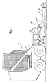
- the rotary mower attachment unit 10 includes a mower deck or housing 12, a cutting blade 14 rotatable within the mower deck 12, a motor 16 for driving the blade 14, and a blade cut off mechanism 20 for disabling rotation of the blade 14 when an end of the mower deck 12 is raised a predetermined distance from a ground surface 22. As soon as the end of the mower deck 12 returns below the predetermined distance from the ground surface 22 the blade 14 is again enabled for cutting.
- a mounting plate 25 attaches the rotary mower attachment unit 10 to a boom arm 13 of the skid steer loader 11.
- the rotary mower attachment unit 10 may be displaced with respect to the ground surface by operation of a boom arm hydraulic piston and cylinder 15 or a bucket-tip hydraulic piston and cylinder 17.
- the mower deck 12, the cutting blade 14, and the motor 16 are conventional components well known in the art of rotary mowers and so are only explained briefly herein.
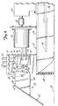
- the hinge section 64 of the mounting plate includes a hinge plates 68 at each end of the mating section 62 for engaging the towers 42 in the mower deck 12, a pair hinge pins 70 for hingedly engaging the hinge plate 68 to towers 42, and a pair of stop mechanisms 90 for limiting the pivotal range of the mower deck 12.
- One of the hinge returns 64 supports a portion of the blade cut off mechanism 20 as further explained below.
- Each hinge pin 70 is mounted in a free swivel arrangement allowing the mower deck 12 to pivot upward and downward in relation to the fixed mounting plate 25.
- the stop pin 92 engages a lower edge of the slot 93 thereby allowing the entire mower deck 12 to be raised off the ground surface 22 to transport the rotary mower attachment unit 10 or to move the mower deck 12 if it becomes stuck in mud or the like or in the event of an unmowable obstacle on the ground surface.
Landscapes
- Life Sciences & Earth Sciences (AREA)
- Environmental Sciences (AREA)
- Harvester Elements (AREA)
Claims (10)
- Rotormähereinheit oder Werkzeugbefestigungseinheit (10) für einen Vielwerkzeughalter, wie zum Beispiel einen Kompaktlader (11), mit einem Gehäuse (12), einem im Gehäuse (12) zur Drehung angebrachten Messer (14), einem mit dem Gehäuse (12) verbundenen Motor (16) zum Antreiben des Messers (14), wobei das Gehäuse (12) derart gestaltet ist, dass es durch den Vielwerkzeughalter vom Boden abgehoben und auf diesen abgesenkt werden kann; gekennzeichnet durch einen Betätigungsmechanismus (20) zum Abstellen der Drehung des Messers in Abhängigkeit des Anhebens des Gehäuses (12) um einen vorbestimmten Abstand von der Bodenfläche durch den Vielwerkzeughalter.
- Rotormäher- oder Werkzeugbefestigungseinheit (10) nach Anspruch 1, ferner dadurch gekennzeichnet, dass der Betätigungsmechanismus (20) eine Drehung des Messers (14) in Abhängigkeit des Absenkens des Gehäuses (12) von oberhalb des vorbestimmten Abstands von der Bodenfläche bis unterhalb des vorbestimmten Abstands von der Bodenfläche ermöglicht.
- Rotormäher- oder Werkzeugbefestigungseinheit (10) nach Anspruch 1 oder 2, ferner gekennzeichnet durch eine Montageeinrichtung zum Befestigen des Gehäuses (12) an einem extern betriebenen Fahrzeug.
- Rotormäher- oder Werkzeugbefestigungseinheit (10) nach Anspruch 3, dadurch gekennzeichnet, dass die Montageeinrichtung eine Montageplatte (25) mit einem ersten Abschnitt (62), der an dem extern betriebenen Fahrzeug angebracht ist, und einem zweiten Abschnitt (64) umfasst, der derart schwenkbar an dem Gehäuse (12) angebracht ist, dass das Gehäuse (12) in Bezug auf die Montageplatte (25) schwenkbar ist.
- Rotormäher- oder Werkzeugbefestigungseinheit (10) nach Anspruch 4, dadurch gekennzeichnet, dass der Betätigungsmechanismus (20) eine Einrichtung zum Erfassen des Schwenkens des Gehäuses (12) in Bezug auf die Montageplatte (25) umfasst.
- Rotormäher- oder Werkzeugbefestigungseinheit (10) nach Anspruch 3, ferner gekennzeichnet durch eine Anschlageinrichtung (90), die an der Montageplatte (25) angebracht und mit dem Gehäuse (12) betreibbar ist, um die Schwenkbewegung des Gehäuses (12) in Bezug auf die Montageplatte (25) zu begrenzen.
- Rotormäher- oder Werkzeugbefestigungseinheit (10) nach Anspruch 3, dadurch gekennzeichnet, dass der Motor (16) ein Hydromotor ist, dass Hydraulikschläuche (50, 51, 52, 53) dem Hydromotor (16) Hydraulikflüssigkeit von einem extern betriebenen Fahrzeug zuführen und dass der Betätigungsmechanismus (20) ein Umlenkventil (74) umfasst, das an den Hydraulikschläuchen (50, 51, 52, 53) angebracht ist und derart mit dem Hydromotor (16) betrieben werden kann, dass die Hydraulikflüssigkeit von dem Hydromotor (16) umgelenkt wird, wenn das Gehäuse (12) um den vorbestimmten Abstand von der Bodenfläche (22) verschoben wird.
- Rotormäher- oder Werkzeugbefestigungseinheit (10) nach Anspruch 7, dadurch gekennzeichnet, dass der Betätigungsmechanismus (20) einen Betätigungsknopf (76), der mit dem Umlenkventil (74) betreibbar ist, und eine Nockenfläche (80) umfasst, die derart mit dem Betätigungsknopf (76) betreibbar ist, dass, wenn sich das Gehäuse (12) außer Kontakt mit der Bodenfläche (22) bewegt, sich der Betätigungsknopf (76) entlang der Nockenfläche (80) bewegt, bis der Betätigungsknopf (76) die vorbestimmte Position erreicht, in der das Umlenkventil (74) aktiviert wird.
- Rotormäher- oder Werkzeugbefestigungseinheit (10) nach Anspruch 8, dadurch gekennzeichnet, dass die Betätigungseinrichtung ferner ein Dämpfungsventil (74) umfasst.
- Rotormäher- oder Werkzeugbefestigungseinheit (10) nach Anspruch 3, dadurch gekennzeichnet, dass der Betätigungsmechanismus (20) Strom von dem Motor (16) umlenkt, wenn das Gehäuse (12) nicht parallel mit der Bodenfläche (22) ist, so dass die Drehung des Messers (14) gestoppt wird.
Applications Claiming Priority (3)
| Application Number | Priority Date | Filing Date | Title |
|---|---|---|---|
| US08/310,855 US5435117A (en) | 1994-09-22 | 1994-09-22 | Rotary mower with automatic engine cut off |
| US310855 | 1994-09-22 | ||
| PCT/US1995/009295 WO1996008954A1 (en) | 1994-09-22 | 1995-07-24 | Rotary mower with automatic engine cut off |
Publications (3)
| Publication Number | Publication Date |
|---|---|
| EP0802714A1 EP0802714A1 (de) | 1997-10-29 |
| EP0802714A4 EP0802714A4 (de) | 2000-03-01 |
| EP0802714B1 true EP0802714B1 (de) | 2003-09-24 |
Family
ID=23204387
Family Applications (1)
| Application Number | Title | Priority Date | Filing Date |
|---|---|---|---|
| EP95928116A Expired - Lifetime EP0802714B1 (de) | 1994-09-22 | 1995-07-24 | Rotormäher mit automatischer motorabstellung |
Country Status (6)
| Country | Link |
|---|---|
| US (1) | US5435117A (de) |
| EP (1) | EP0802714B1 (de) |
| AU (1) | AU696589B2 (de) |
| CA (1) | CA2199931C (de) |
| DE (1) | DE69531840T2 (de) |
| WO (1) | WO1996008954A1 (de) |
Families Citing this family (34)
| Publication number | Priority date | Publication date | Assignee | Title |
|---|---|---|---|---|
| US5666794A (en) * | 1995-11-21 | 1997-09-16 | Palm Sales, Inc. | Flail mower attachment for a skid steer vehicle |
| US5706638A (en) * | 1996-01-22 | 1998-01-13 | Alitec Corporation | Mower with automatic power cut-off |
| US6116007A (en) * | 1998-03-02 | 2000-09-12 | Clark Equipment Company | Four bar linkage mounting for mowers |
| US6138444A (en) | 1998-04-01 | 2000-10-31 | Torras, Sr.; Robert M. | Ground clearing brush cutter and mulcher with a rigid height adjustment mechanism |
| US6438931B1 (en) * | 1999-10-05 | 2002-08-27 | Wright Manufacturing, Inc. | Power lawn mower including shortened control arms for use in deck lift system |
| US6357993B1 (en) * | 2000-02-17 | 2002-03-19 | Farmers' Factory Company | Construction equipment implement and method |
| US7340877B2 (en) * | 2001-09-19 | 2008-03-11 | Crosstech Manufacturing, Inc. | Cutter unit support roller |
| US6832466B2 (en) | 2001-09-19 | 2004-12-21 | Cross Tech Manufacturing, Inc. | Brush cutter emergency stop system |
| US20050193702A1 (en) * | 2001-09-19 | 2005-09-08 | Anderson Steve K. | Brush cutter emergency stop system |
| US20040128969A1 (en) * | 2002-12-12 | 2004-07-08 | Robert Meurer | Mower accessory for attachment to a front end of a skid-steer loader |
| US7096900B2 (en) * | 2003-06-04 | 2006-08-29 | Loftness Specialized Equipment, Inc. | Tree cutting attachment for work vehicle |
| US6871485B2 (en) | 2003-06-04 | 2005-03-29 | Loftness Specialized Equipment, Inc. | Tree cutting attachment for skid loader |
| CA2439514A1 (en) * | 2003-09-04 | 2005-03-04 | Allan D. Rookes | Tractor mountable brush cutting device |
| US20050060975A1 (en) * | 2003-09-19 | 2005-03-24 | Mcclymonds Dean L. | Remotely controlled mowing device |
| US7056079B2 (en) * | 2003-11-10 | 2006-06-06 | Caterpillar Inc. | Linkage assembly restraint |
| US6983583B2 (en) * | 2003-11-21 | 2006-01-10 | Ariens Company | Lawnmower tilt sensor apparatus and method |
| US20060053761A1 (en) * | 2004-09-10 | 2006-03-16 | Clark Equipment Company | Floating attachment linkage |
| USD581956S1 (en) * | 2006-10-31 | 2008-12-02 | Sas Dairon | Machine for shredding plants or vegetables |
| USD633112S1 (en) * | 2008-12-03 | 2011-02-22 | Sas Dairon | Machine for grinding vegetation |
| US8272197B2 (en) * | 2010-06-15 | 2012-09-25 | Man-Young Jung | Handheld lawn mower |
| US9554514B2 (en) | 2013-03-14 | 2017-01-31 | Clark Equipment Company | Rotary cutter implement with ball joint connection to a power machine |
| US9648806B2 (en) * | 2015-04-28 | 2017-05-16 | Crosstech Manufacturing, Inc. | Hydraulic brush cutter |
| US9948048B2 (en) * | 2015-05-15 | 2018-04-17 | Yazaki North America, Inc. | Splitter terminal and connector |
| US10375891B2 (en) * | 2016-07-05 | 2019-08-13 | Charles H. Martin | Agricultural device |
| US20180338421A1 (en) * | 2017-11-10 | 2018-11-29 | Larry Wayne Christian | Articulating and Variable Height Vegetation Cutter |
| US10470364B1 (en) * | 2018-01-30 | 2019-11-12 | Travis William Odom | Removably attachable adjustable cutting apparatus and method |
| US11382263B2 (en) * | 2018-02-19 | 2022-07-12 | Exmark Manufacturing Company, Incorporated | Articulating cutting deck |
| US11564356B2 (en) * | 2018-03-21 | 2023-01-31 | Johnny E. Grice | Tree branch and brush cutting attachment |
| US10533300B1 (en) * | 2018-08-04 | 2020-01-14 | David Armas | Automatic grader stabilizer |
| US11937543B2 (en) * | 2020-01-16 | 2024-03-26 | The Modern Group, Ltd. | Brush cutter |
| USD990524S1 (en) * | 2021-01-28 | 2023-06-27 | Adds Up Engineering Pty Ltd | Foldable slasher |
| USD984487S1 (en) * | 2021-09-03 | 2023-04-25 | Lane Shark Usa, Llc | Maneuverable vegetation cutting apparatus |
| USD1018600S1 (en) * | 2022-08-10 | 2024-03-19 | Blue Diamond Attachments, Llc | Brush cutter |
| USD1026044S1 (en) * | 2022-09-06 | 2024-05-07 | Greenworks (Jiangsu) Co. Ltd. | Mower deck |
Family Cites Families (13)
| Publication number | Priority date | Publication date | Assignee | Title |
|---|---|---|---|---|
| US2523014A (en) * | 1947-07-15 | 1950-09-19 | Herbert L Gooch | Hydraulic mower |
| DE1507434B1 (de) * | 1966-12-06 | 1970-04-02 | Elmar Wolf | Rutschkupplung fuer waagerecht umlaufendes,motorisch angetriebenes Messer eines Rasenmaehers |
| US3633699A (en) * | 1970-03-02 | 1972-01-11 | Deere & Co | Control means for tractor-mounted driven implement |
| US3773156A (en) * | 1972-07-24 | 1973-11-20 | Warner Electric Brake & Clutch | Clutch-brake and motor circuit for engine-driven implements |
| US3874149A (en) * | 1972-09-15 | 1975-04-01 | Lester H Seifert | Self-propelled lawn mower |
| US4126989A (en) * | 1974-05-31 | 1978-11-28 | Multinorm B.V. | Mowing implement |
| US4206580A (en) * | 1977-12-01 | 1980-06-10 | Traux Clarence E | Mower device |
| US4183195A (en) * | 1978-08-22 | 1980-01-15 | Terrain King Corporation | Mounting apparatus for offset mower |
| US4570425A (en) * | 1983-06-09 | 1986-02-18 | Roseman Mower Corporation | Hydraulically operated gang mower trailer |
| US4538400A (en) * | 1984-06-11 | 1985-09-03 | Allied Products Corporation | Rotary mower having ground supported frames |
| US4697404A (en) * | 1985-10-01 | 1987-10-06 | Brockmeier Sod Farms | Tractor mower system |
| US5005344A (en) * | 1990-01-08 | 1991-04-09 | Mccracken Doc J | Light brush and grass hydraulic mower |
| US5123234A (en) * | 1990-10-02 | 1992-06-23 | Kubota Corporation | Working vehicle having a mower unit vertically movable relative to a vehicle body |
-
1994
- 1994-09-22 US US08/310,855 patent/US5435117A/en not_active Expired - Lifetime
-
1995
- 1995-07-24 CA CA002199931A patent/CA2199931C/en not_active Expired - Lifetime
- 1995-07-24 WO PCT/US1995/009295 patent/WO1996008954A1/en not_active Ceased
- 1995-07-24 EP EP95928116A patent/EP0802714B1/de not_active Expired - Lifetime
- 1995-07-24 AU AU31990/95A patent/AU696589B2/en not_active Ceased
- 1995-07-24 DE DE69531840T patent/DE69531840T2/de not_active Expired - Fee Related
Also Published As
| Publication number | Publication date |
|---|---|
| US5435117A (en) | 1995-07-25 |
| CA2199931C (en) | 2004-12-14 |
| AU696589B2 (en) | 1998-09-17 |
| WO1996008954A1 (en) | 1996-03-28 |
| EP0802714A1 (de) | 1997-10-29 |
| CA2199931A1 (en) | 1996-03-28 |
| AU3199095A (en) | 1996-04-09 |
| DE69531840T2 (de) | 2004-05-06 |
| DE69531840D1 (de) | 2003-10-30 |
| EP0802714A4 (de) | 2000-03-01 |
Similar Documents
| Publication | Publication Date | Title |
|---|---|---|
| EP0802714B1 (de) | Rotormäher mit automatischer motorabstellung | |
| US7340875B2 (en) | Power tool emergency stop system | |
| EP2134905B1 (de) | Hydraulikkraftverwaltungssystem | |
| AU717010B2 (en) | Auxiliary interlock control system for power machine | |
| CA2092668C (en) | Hinged-blade roadside mower | |
| US6354081B1 (en) | Attachment for skid steer loader or other commercial work vehicle having wireless hydraulic sequencing block | |
| EP1364572B1 (de) | Buschmäherfahrzeug | |
| US4459767A (en) | Ditcher head assembly for cleaning ditches | |
| US5822960A (en) | Reel mower | |
| WO2006014337A2 (en) | Forestry machine with hydraulic system and method for rotor braking | |
| US20050120693A1 (en) | Brush cutting breakaway system | |
| EP2248408B1 (de) | Hebemechanismus | |
| US5733059A (en) | Apparatus for coupling a cutting tool to a vehicle | |
| US7340877B2 (en) | Cutter unit support roller | |
| US9648806B2 (en) | Hydraulic brush cutter | |
| CN114457866A (zh) | 切割装置和救援车辆 | |
| US20050193702A1 (en) | Brush cutter emergency stop system | |
| AU2015257510A1 (en) | Agricultural machine comprising an improved device for controlling a shield | |
| US12467230B2 (en) | Working machine | |
| CA1318508C (en) | Single lever control for selectively effecting lifting of multiple cutting units of a mower | |
| MXPA98009086A (en) | Appliance to couple a cutting tool to a vehic | |
| GB2115669A (en) | Mowers | |
| JPS61139311A (ja) | コンバインにおける刈取部保護装置 |
Legal Events
| Date | Code | Title | Description |
|---|---|---|---|
| PUAI | Public reference made under article 153(3) epc to a published international application that has entered the european phase |
Free format text: ORIGINAL CODE: 0009012 |
|
| 17P | Request for examination filed |
Effective date: 19970410 |
|
| AK | Designated contracting states |
Kind code of ref document: A1 Designated state(s): BE DE FR GB IT |
|
| A4 | Supplementary search report drawn up and despatched |
Effective date: 20000113 |
|
| AK | Designated contracting states |
Kind code of ref document: A4 Designated state(s): BE DE FR GB IT |
|
| 17Q | First examination report despatched |
Effective date: 20010913 |
|
| GRAH | Despatch of communication of intention to grant a patent |
Free format text: ORIGINAL CODE: EPIDOS IGRA |
|
| GRAH | Despatch of communication of intention to grant a patent |
Free format text: ORIGINAL CODE: EPIDOS IGRA |
|
| GRAA | (expected) grant |
Free format text: ORIGINAL CODE: 0009210 |
|
| AK | Designated contracting states |
Kind code of ref document: B1 Designated state(s): BE DE FR GB IT |
|
| PG25 | Lapsed in a contracting state [announced via postgrant information from national office to epo] |
Ref country code: BE Free format text: LAPSE BECAUSE OF FAILURE TO SUBMIT A TRANSLATION OF THE DESCRIPTION OR TO PAY THE FEE WITHIN THE PRESCRIBED TIME-LIMIT Effective date: 20030924 |
|
| REG | Reference to a national code |
Ref country code: GB Ref legal event code: FG4D |
|
| REF | Corresponds to: |
Ref document number: 69531840 Country of ref document: DE Date of ref document: 20031030 Kind code of ref document: P |
|
| ET | Fr: translation filed | ||
| PLBE | No opposition filed within time limit |
Free format text: ORIGINAL CODE: 0009261 |
|
| STAA | Information on the status of an ep patent application or granted ep patent |
Free format text: STATUS: NO OPPOSITION FILED WITHIN TIME LIMIT |
|
| 26N | No opposition filed |
Effective date: 20040625 |
|
| PGFP | Annual fee paid to national office [announced via postgrant information from national office to epo] |
Ref country code: DE Payment date: 20080829 Year of fee payment: 14 |
|
| PGFP | Annual fee paid to national office [announced via postgrant information from national office to epo] |
Ref country code: IT Payment date: 20080726 Year of fee payment: 14 Ref country code: FR Payment date: 20080729 Year of fee payment: 14 |
|
| PGFP | Annual fee paid to national office [announced via postgrant information from national office to epo] |
Ref country code: GB Payment date: 20080729 Year of fee payment: 14 |
|
| GBPC | Gb: european patent ceased through non-payment of renewal fee |
Effective date: 20090724 |
|
| REG | Reference to a national code |
Ref country code: FR Ref legal event code: ST Effective date: 20100331 |
|
| PG25 | Lapsed in a contracting state [announced via postgrant information from national office to epo] |
Ref country code: FR Free format text: LAPSE BECAUSE OF NON-PAYMENT OF DUE FEES Effective date: 20090731 |
|
| PG25 | Lapsed in a contracting state [announced via postgrant information from national office to epo] |
Ref country code: GB Free format text: LAPSE BECAUSE OF NON-PAYMENT OF DUE FEES Effective date: 20090724 |
|
| PG25 | Lapsed in a contracting state [announced via postgrant information from national office to epo] |
Ref country code: DE Free format text: LAPSE BECAUSE OF NON-PAYMENT OF DUE FEES Effective date: 20100202 |
|
| PG25 | Lapsed in a contracting state [announced via postgrant information from national office to epo] |
Ref country code: IT Free format text: LAPSE BECAUSE OF NON-PAYMENT OF DUE FEES Effective date: 20090724 |