EP0802714B1 - Rotary mower with automatic engine cut off - Google Patents
Rotary mower with automatic engine cut off Download PDFInfo
- Publication number
- EP0802714B1 EP0802714B1 EP95928116A EP95928116A EP0802714B1 EP 0802714 B1 EP0802714 B1 EP 0802714B1 EP 95928116 A EP95928116 A EP 95928116A EP 95928116 A EP95928116 A EP 95928116A EP 0802714 B1 EP0802714 B1 EP 0802714B1
- Authority
- EP
- European Patent Office
- Prior art keywords
- housing
- attachment unit
- rotary mower
- ground surface
- tool attachment
- Prior art date
- Legal status (The legal status is an assumption and is not a legal conclusion. Google has not performed a legal analysis and makes no representation as to the accuracy of the status listed.)
- Expired - Lifetime
Links
Images


Classifications
-
- A—HUMAN NECESSITIES
- A01—AGRICULTURE; FORESTRY; ANIMAL HUSBANDRY; HUNTING; TRAPPING; FISHING
- A01D—HARVESTING; MOWING
- A01D34/00—Mowers; Mowing apparatus of harvesters
- A01D34/01—Mowers; Mowing apparatus of harvesters characterised by features relating to the type of cutting apparatus
- A01D34/412—Mowers; Mowing apparatus of harvesters characterised by features relating to the type of cutting apparatus having rotating cutters
- A01D34/63—Mowers; Mowing apparatus of harvesters characterised by features relating to the type of cutting apparatus having rotating cutters having cutters rotating about a vertical axis
- A01D34/67—Mowers; Mowing apparatus of harvesters characterised by features relating to the type of cutting apparatus having rotating cutters having cutters rotating about a vertical axis hand-guided by a walking operator
- A01D34/68—Mowers; Mowing apparatus of harvesters characterised by features relating to the type of cutting apparatus having rotating cutters having cutters rotating about a vertical axis hand-guided by a walking operator with motor driven cutters or wheels
- A01D34/6806—Driving mechanisms
-
- A—HUMAN NECESSITIES
- A01—AGRICULTURE; FORESTRY; ANIMAL HUSBANDRY; HUNTING; TRAPPING; FISHING
- A01D—HARVESTING; MOWING
- A01D34/00—Mowers; Mowing apparatus of harvesters
- A01D34/01—Mowers; Mowing apparatus of harvesters characterised by features relating to the type of cutting apparatus
- A01D34/02—Mowers; Mowing apparatus of harvesters characterised by features relating to the type of cutting apparatus having reciprocating cutters
- A01D34/24—Lifting devices for the cutter-bar
- A01D34/27—Devices for disengaging the knife-driving mechanisms during the lifting of the cutter-bar
-
- A—HUMAN NECESSITIES
- A01—AGRICULTURE; FORESTRY; ANIMAL HUSBANDRY; HUNTING; TRAPPING; FISHING
- A01D—HARVESTING; MOWING
- A01D34/00—Mowers; Mowing apparatus of harvesters
- A01D34/01—Mowers; Mowing apparatus of harvesters characterised by features relating to the type of cutting apparatus
- A01D34/412—Mowers; Mowing apparatus of harvesters characterised by features relating to the type of cutting apparatus having rotating cutters
- A01D34/63—Mowers; Mowing apparatus of harvesters characterised by features relating to the type of cutting apparatus having rotating cutters having cutters rotating about a vertical axis
- A01D34/64—Mowers; Mowing apparatus of harvesters characterised by features relating to the type of cutting apparatus having rotating cutters having cutters rotating about a vertical axis mounted on a vehicle, e.g. a tractor, or drawn by an animal or a vehicle
-
- A—HUMAN NECESSITIES
- A01—AGRICULTURE; FORESTRY; ANIMAL HUSBANDRY; HUNTING; TRAPPING; FISHING
- A01D—HARVESTING; MOWING
- A01D34/00—Mowers; Mowing apparatus of harvesters
- A01D34/01—Mowers; Mowing apparatus of harvesters characterised by features relating to the type of cutting apparatus
- A01D34/412—Mowers; Mowing apparatus of harvesters characterised by features relating to the type of cutting apparatus having rotating cutters
- A01D34/63—Mowers; Mowing apparatus of harvesters characterised by features relating to the type of cutting apparatus having rotating cutters having cutters rotating about a vertical axis
- A01D34/64—Mowers; Mowing apparatus of harvesters characterised by features relating to the type of cutting apparatus having rotating cutters having cutters rotating about a vertical axis mounted on a vehicle, e.g. a tractor, or drawn by an animal or a vehicle
- A01D2034/645—Lifting means for the cutter of the lawnmower mounted at the front of the vehicle for inspection and maintenance
-
- A—HUMAN NECESSITIES
- A01—AGRICULTURE; FORESTRY; ANIMAL HUSBANDRY; HUNTING; TRAPPING; FISHING
- A01D—HARVESTING; MOWING
- A01D2101/00—Lawn-mowers
Definitions
- Free standing rotary mowers are independent units which include a mower deck, a cutting blade contained within the mower deck, either an electric or a gas engine for driving the cutting blade, and a frame structure including a wheel base allowing the mower deck to be over a ground surface.
- Rotary mower attachment units are for use with skid steer loaders or other self-powered vehicles. These rotary mower attachment units include a mower deck, a cutting blade contained within the mower deck, a motor for driving the cutting blade, and a mounting plate for mounting the rotary mower attachment to the loader or other vehicle.
- the motor of the rotary mower attachment units is powered by the energy produced by the self-powered vehicle to which the unit is attached.
- rotary mower attachment units for skid steer loaders often include hydraulic motors which are connected to the hydraulic system of the loader.
- Document US-A-4,538,400 relates to a three section mower having one or more wing frames which are hingedly connected to a main frame. When the wing frames are pivoted at an angle, shut off mechanisms for the wing frames will turn off the power by disabling the power take off connection.
- the rotary mower attachment unit 10 includes a mower deck or housing 12, a cutting blade 14 rotatable within the mower deck 12, a motor 16 for driving the blade 14, and a blade cut off mechanism 20 for disabling rotation of the blade 14 when an end of the mower deck 12 is raised a predetermined distance from a ground surface 22. As soon as the end of the mower deck 12 returns below the predetermined distance from the ground surface 22 the blade 14 is again enabled for cutting.
- a mounting plate 25 attaches the rotary mower attachment unit 10 to a boom arm 13 of the skid steer loader 11.
- the rotary mower attachment unit 10 may be displaced with respect to the ground surface by operation of a boom arm hydraulic piston and cylinder 15 or a bucket-tip hydraulic piston and cylinder 17.
- the mower deck 12, the cutting blade 14, and the motor 16 are conventional components well known in the art of rotary mowers and so are only explained briefly herein.
- the hinge section 64 of the mounting plate includes a hinge plates 68 at each end of the mating section 62 for engaging the towers 42 in the mower deck 12, a pair hinge pins 70 for hingedly engaging the hinge plate 68 to towers 42, and a pair of stop mechanisms 90 for limiting the pivotal range of the mower deck 12.
- One of the hinge returns 64 supports a portion of the blade cut off mechanism 20 as further explained below.
- Each hinge pin 70 is mounted in a free swivel arrangement allowing the mower deck 12 to pivot upward and downward in relation to the fixed mounting plate 25.
- the stop pin 92 engages a lower edge of the slot 93 thereby allowing the entire mower deck 12 to be raised off the ground surface 22 to transport the rotary mower attachment unit 10 or to move the mower deck 12 if it becomes stuck in mud or the like or in the event of an unmowable obstacle on the ground surface.
Landscapes
- Life Sciences & Earth Sciences (AREA)
- Environmental Sciences (AREA)
- Harvester Elements (AREA)
Abstract
Description
- The present invention relates to rotary mowers and brush cutters (hereinafter collectively referred to as rotary mowers), which run over a ground surface and which have a cutting blade for cutting grass, weeds, brush and the like, and more particularly, to a motorized rotary mower having an automatic engine cut off or blade control. The present invention also has application to any tool attachment unit which includes a rotating cutting blade or the like, and which is attachable to a multi-tool carrier such as a skid steer loader.
- There are two basic types of rotary mowers: free standing rotary mowers and rotary mower attachment units. Free standing rotary mowers are independent units which include a mower deck, a cutting blade contained within the mower deck, either an electric or a gas engine for driving the cutting blade, and a frame structure including a wheel base allowing the mower deck to be over a ground surface. Rotary mower attachment units are for use with skid steer loaders or other self-powered vehicles. These rotary mower attachment units include a mower deck, a cutting blade contained within the mower deck, a motor for driving the cutting blade, and a mounting plate for mounting the rotary mower attachment to the loader or other vehicle. The motor of the rotary mower attachment units is powered by the energy produced by the self-powered vehicle to which the unit is attached. For example, rotary mower attachment units for skid steer loaders often include hydraulic motors which are connected to the hydraulic system of the loader.
- One of the problems common to all mowers and in particular to rotary mower attachment units is that the cutting blade continues to rotate regardless of the positioning of the mower deck. Some mowers include hand-operated blade cut-off switches which deactivate the entire mower when the operator releases the switch. However, a dangerous and unsafe situation persists with all rotary mowers in that when the mower deck is pivoted or raised off the ground surface for transport or for avoiding objects on the ground surface, the blade is exposed and continues to rotate.
- Document US-A-4,538,400 relates to a three section mower having one or more wing frames which are hingedly connected to a main frame. When the wing frames are pivoted at an angle, shut off mechanisms for the wing frames will turn off the power by disabling the power take off connection.
- Document US-A-5,123,234 discloses a working vehicle having a grass cutting unit which is vertically movable relative to a vehicle body, a lift mechanism for raising and lowering the grass cutting unit, a clutch for making and breaking transmission of a blade driving power to the grass cutting unit and a device for controlling the lift mechanism.
- The present invention relates a rotary mower or tool attachment unit which is attachable to a multi-tool carrier such as a skid steer loader according to claim 1. The actuator mechanism thus reduces or eliminates the unsafe situation where the rotating blade is exposed when the housing is raised.
- If the present invention is embodied on a rotary mower attachment unit, a mounting plate is provided for mounting the housing to an externally driven vehicle such as a skid steer loader. The ends of the mounting plate are hingedly attached to the housing such that the housing pivots with respect to the mounting plate thereby triggering the actuator mechanism. If a hydraulic motor is employed, the actuator mechanism includes a diverter valve, an actuator button and a cam surface. The diverter valve diverts hydraulic fluid from the hydraulic motor when the end of the housing is a predetermined distance from the ground surface. The actuator button operates with the diverter valve and the cam surface such that as the end of the housing moves out of contact with the ground surface the actuator button moves along the cam surface until the actuator button reaches a predetermined position wherein the diverter valve is activated.
- It is to be understood that the present invention may be embodied in any type of mower, regardless of the type of motor employed for driving the cutting blade. It is also to be understood that the present invention may be embodied in any type of tool attachment unit for a multi-tool carrier unit such as a skid steer loader, including trenchers, sweepers, angle brooms, hydraulic snowblowers, stump grinders, planers, wheel saws, augers, tillers, or the like.
-
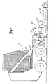
- Figure 1 is a side elevation of a skid steer loader with a rotary mower attachment unit according to the present invention, the rotary mower attachment unit being shown in a first position;
- Figure 2 is a side elevation of a skid steer loader and rotary mower attachment unit with the rotary mower attachment unit shown in a second position;
- Figure 3 is a top plan view of the rotary mower attachment unit; and
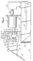
- Figure 4 is an enlarged side elevation of a portion of the rotary mower attachment unit.
-
- It is to be understood that the present invention has application to any type of rotary mower regardless of whether the mower is an attachment unit or a free standing unit. In addition, it is to be understood that the principles of the present invention have application to any tool attachment unit for multi-tool carrier unit such as a skid steer loader with a rotating blade or the like. In addition, the present invention has application to any rotary mower regardless of the type of motor used to rotate the blade and may be used with, for example, gas powered, electric or hydraulic motors. Thus, while the present invention is described with reference to a hydraulically operated rotary
mower attachment unit 10 for askid steer loader 11, additional applications will be apparent. - As shown in Figures 1 and 2, the rotary
mower attachment unit 10 includes a mower deck orhousing 12, acutting blade 14 rotatable within themower deck 12, amotor 16 for driving theblade 14, and a blade cut offmechanism 20 for disabling rotation of theblade 14 when an end of themower deck 12 is raised a predetermined distance from aground surface 22. As soon as the end of themower deck 12 returns below the predetermined distance from theground surface 22 theblade 14 is again enabled for cutting. Amounting plate 25 attaches the rotarymower attachment unit 10 to aboom arm 13 of theskid steer loader 11. The rotarymower attachment unit 10 may be displaced with respect to the ground surface by operation of a boom arm hydraulic piston andcylinder 15 or a bucket-tip hydraulic piston andcylinder 17. - The
mower deck 12, thecutting blade 14, and themotor 16 are conventional components well known in the art of rotary mowers and so are only explained briefly herein. - As shown in Figure 3 the
mower deck 12 is of a generally square, metallic construction and includes atop surface 32, afirst side surface 34, a second side surface 36 a front end 38. arear end 40, and a pair oftowers 42 in each of the corners at therear end 40 of themower deck 12. Eachtower 42 is rectangular and has dimensions of approximately 6" in width, 10" in length, and 12" in height. Eachtower 42 is constructed of steel and is welded to the corners of therear end 40 of themower deck 12. Eachtower 42 provides a mounting location for the mounting plate, and one of the towers is a housing for the blade cut offmechanism 20 as further described below. Thefirst side surface 34 andsecond side surface 36 extend between a front end 38 and arear end 40 of themower deck 12 and run generally in contact with theground surface 22 to be mowed. The front end 38 and therear end 40 of themower deck 12 are open to allow the surface to be mowed to enter themower deck 12 and be exposed to thecutting blade 14. A safety chain 44 (see Figures 1 and 2) attached across the front andrear ends 38 and 40 of themower deck 12 prevents flying debris from exiting themower deck 12 at high velocities. - The
cutting blade 14 includes a center mounting plate and a pair of mower blades attached to the mounting plate 180° apart from each other. The cutting surfaces of thecutting blade 14 are positioned so as to cut in only one direction. - As shown in detail in Figures 3 and 4, the
motor 16 is mounted to thetop surface 32 of themower deck 12. Themotor 16 is a hydraulic motor connected to and powered by the hydraulic system (not shown) of theskid steer loader 11 throughsupply hoses return hoses skid steer loader 11 to themotor 16. Thereturn hoses motor 16 to theskid steer loader 11. Acoupling 56 transfers the output of thehydraulic motor 16 to anangle drive 60 which redirects the output of thehydraulic motor 16 to thecutting blade 14. - The
mounting plate 25 includes amating section 62 fixedly attached to theboom arm 13 of theskid steer load 11 for securing the rotarymower attachment unit 10 to theloader 11, and ahinge section 64 pivotally attaching themower deck 12 to themating section 62. There are a variety of well known constructions available for themating section 62 of themounting plate 25 depending on the particular type and manufacturer of the loader to which the rotarymower attachment unit 10 is mounted. On the other hand, thehinge section 64 of the mounting plate includes ahinge plates 68 at each end of themating section 62 for engaging thetowers 42 in themower deck 12, apair hinge pins 70 for hingedly engaging thehinge plate 68 totowers 42, and a pair ofstop mechanisms 90 for limiting the pivotal range of themower deck 12. One of the hinge returns 64 supports a portion of the blade cut offmechanism 20 as further explained below. Eachhinge pin 70 is mounted in a free swivel arrangement allowing themower deck 12 to pivot upward and downward in relation to the fixedmounting plate 25. - The blade cut off
mechanism 20 includes adiverter switch 74 for diverting the hydraulic fluid from passing through thehydraulic motor 16, and aplunger actuator 76 operable withdiverter switch 74 for triggering thediverter switch 74, and acam surface 80 andcam follower 82 which control theplunger actuator 76. The blade cut offmechanism 20 is mounted in one of the towers on the top surface 37 of themower deck 12. Thediverter switch 74 is a diverter/cushion valve having ansupply input 75 for receiving hydraulic fluid from theloader 11 fromsupply line 50, asupply output 76 for outputting hydraulic fluid to thehydraulic motor 16 alongline 51, areturn input 77 for receiving hydraulic fluid from thehydraulic motor 16 alongline 52, and areturn output 78 for returning hydraulic fluid to theloader 11 alongline 53. The diverter/cushion valve is a combination of a diverter valve which diverts the hydraulic fluid away from thehydraulic motor 16 and a cushion valve which provides a controlled cut off of the hydraulic fluid to avoid breakage or jamming of thehydraulic motor 16 coupling orangle drive 60. A bias spring (not shown) operates theplunger actuator 76 for triggering the diverter/cushion valve. In a normal position (see Figure 1) theplunger actuator 76 is compressed and the diverter/cushion valve is in a position permitting hydraulic fluid to flow to thehydraulic motor 16, while in the cut-off position (see Figure 2) theplunger actuator 76 is extended and the diverter/cushion valve is in a position redirecting the hydraulic fluid away from thehydraulic motor 16 and back to theloader 11. The combination diverter/cushion valve andplunger actuator 76 is available as Part No. RC6030R from J.N. Fauver Company, 10286 W. 70th Street, Eden Prairie, Minnesota. - The
stop mechanism 90 limits the pivotal range of themower deck 12 and includes apin 92 mounted to thetower 42 and operable with aslot 93 on the hinge plate. Thestop pin 92 moves within theslot 93 thereby allowing themower deck 12 to pivot in a range determined by the length of theslot 93. The longer theslot 93 the more angle is achieved between themower deck 12 and the mountingplate 25 and this varies depending on the application. When theboom arm piston 15 or bucket-tip piston 17 is activated the rear end of themower deck 12 is raised upward. At a predetermined distance above from the ground surface thestop pin 92 engages a lower edge of theslot 93 thereby allowing theentire mower deck 12 to be raised off theground surface 22 to transport the rotarymower attachment unit 10 or to move themower deck 12 if it becomes stuck in mud or the like or in the event of an unmowable obstacle on the ground surface. - The
cam surface 80 is located on the end of thehinge plate 68. Thecam surface 20 includes acenter ridge 85 and recessed portions on either side of theridge 85. In the run position thecam follower 82 is positioned on theridge 85 such that hydraulic fluid flows through the diverter/cushion valve into thehydraulic motor 16. In the run position both ends of themower deck 12 are in contact with and parallel to the ground surface. If theboom 13 is raised or lowered so that an end of themower deck 12 is displaced with respect to the ground surface, thecam follower 82 rolls off theridge 85 and theplunger actuator 76 thereby activates the diverter/cushion valve to redirect the hydraulic fluid flowing outsupply output 76 back through thereturn outlet 78 such that no hydraulic fluid passes alonglines hydraulic motor 16. - The length of the
ridge 85 determines the distance above theground surface 22 which an end of themower deck 12 must be raised in order to deactivate thecutting blade 14. The longer theridge 85 the greater the pivot angle between themower deck 12 and the mountingplate 25 needed in order for theplunger actuator 76 to activate the diverter/cushion valve and cut off hydraulic fluid to thehydraulic motor 16. In other words, the shorter theridge 85 the lower the displacement of an end of themower deck 12 with respect to theground surface 22 needed and the larger theridge 85 the greater the displacement of an end of themower deck 12 needed in order to stop cuttingblade 14. - It is to be understood that the
plunger actuator 76,cam follower 82 andcam surface 80 may be arranged such that the cam surface includes actuator 76 a central recess surrounded by ridges when themower deck 12 is in full contact with theground surface 22 and that upon movement of the mountingplate 25 with respect to themower deck 12 theplunger actuator 76 is depressed thereby activating the diverter/cushion valve. The former arrangement is preferred in that it provides a fail/safe "off' position in the event of a malfunction in the blade cut offmechanism 20 wherein thecutting blade 14 in not engaged. - In operation, the rotary
mower attachment unit 10 is mounted on theboom arm 13 of the skid steer loader by engagement of the mountingplate 25 to a corresponding section or the bucket tip. The bucket tiphydraulic cylinder 17 is adjusted to maintain themower deck 12 in full contact with ground surface and such that theactuator plunger 76 is centered on theridge 85 of thecam surface 80. In this position hydraulic fluid from the hydraulic system of theloader 11 flows through the hydraulic hoses 50-53 and diverter/cushion valve into thehydraulic motor 16 for rotating thecutting blade 14. As themower deck 12 skids along theground surface 22 themower deck 12 pivots about of thehinge pin 70 with respect to the mountingplate 25. The length of theridge 85 of thecam surface 80 is selected such that the general movement of themower deck 12 along theground surface 22 does not actuate the diverter/cushion valve. However, when either thehydraulic cylinder 17 for the bucket tip or thehydraulic cylinder 15 for theboom arm 11 is moved such that themower deck 12 is displaced from theground surface 22 for avoiding unmowable objects on the ground surface or for transport or the like, the angle between themower deck 12 and thehinge plate 25 changes. The angle changes to the point where thecam follower 82 rolls off theridge 85 into the recess such that theplunger actuator 76 thereby triggers the diverter/cushion valve to cut off the flow of hydraulic fluid to thehydraulic motor 16. More particularly, hydraulic fluid entering thesupply inlet 75 of the diverter/cushion valve along thesupply line 50 is redirected to thereturn outlet 78 of the diverter/cushion valve back to theloader 11 alongreturn line 53. Thus, with no hydraulic fluid flowing through thehydraulic motor 16 thecutting blade 14 does not rotate. As themower deck 12 continues to be raised off the ground surface thepin 92 engages theslot 93 of thetower 42 to fix the angle of themower deck 12 with respect to the mountingplate 25 for transport of the rotarymower attachment unit 10. The length of the slot is selected with respect to the length of theridge 85 of thecam surface 85 such that thehydraulic motor 16 is always cut off before thepin 92 engages an end of theslot 93. Upon placement of themower deck 12 back in contact with theground surface 22 thecam follower 82 again is moved onto theridge 85 thereby resetting the diverter/cushion valve to its original position where the hydraulic fluid flows through thesupply outlet 76 alongsupply line 51 into thehydraulic motor 16 and back through thereturn line 52 intoreturn inlet 77 such that thecutting blade 14 is again rotated. - Although the present invention has been described with reference to preferred embodiments, workers skilled in the art will recognize that changes may be made in form and detail within the scope of the claims.
Claims (10)
- A rotary mower unit or tool attachment unit (10) for a multi-tool carrier such as a skid steer loader (11), having a housing (12); a blade (14) mounted within the housing (12) for rotation; a motor (16) connected to the housing (12) or driving the blade (14) the housing (12) adapted to be raised and lowered to the ground by the multi-tool carrier, and; characterized by an actuator mechanism (20) for disabling rotation of the blade in response to the raising the housing (12) a predetermined distance from the ground surface by the multi-tool carrier.
- A rotary mower, or tool attachment unit (10) of claim 1, further characterized by the actuator mechanism (20) enabling rotation of the blade (14) in response to lowering the housing (12) from above the predetermined distance from the ground surface to below the predetermined distance from the ground surface.
- The rotary mower or tool attachment unit (10) of claims 1 or 2. further characterized by mounting means for mounting the housing (12) to an external powered vehicle.
- The rotary mower or tool attachment unit (10) of claim 3, characterized in that the mounting means includes a mounting plate (25) having a first portion (62) which mounts to the external powered vehicle and a second portion (64) hingedly attached to the housing (12) such that the housing (12) pivots with respect to the mounting plate (25).
- The rotary mower or tool attachment unit (10) of claim 4, characterized in that the actuator mechanism (20) includes means for sensing the pivoting of the housing (12) with respect to the mounting plate (25).
- The rotary mower or tool attachment unit (10) of claim 3, further characterized by stop means (90) mounted to the mounting plate (25) and operable with the housing (12) for limiting the pivotal movement of the housing (12) with respect to the mounting plate (25).
- The rotary mower or tool attachment unit (10) of claim 3, characterized in that the motor (16) is a hydraulic motor, in that hydraulic hoses (50, 51, 52, 53) feed hydraulic fluid from an externally powered vehicle to the hydraulic motor (16) and in that the actuator mechanism (20) includes a diverter valve (74) mounted to the hydraulic hoses (50, 51, 52, 53) and operable with the hydraulic motor (16) such that the hydraulic fluid is diverted from the hydraulic motor (16) when the housing (12) is displaced the predetermined distance from the ground surface (22).
- The rotary mower or tool attachment unit (10) of claim 7, characterized in that the actuator mechanism (20) includes an actuator button (76) operable with the diverter valve (74) and a cam surface (20) operable with the actuator button (76) such that as the housing (12) moves out of contact with the ground surface (22) the actuator button (76) moves along the cam surface (80) until the actuator button (76) reaches the predetermined position wherein the diverter valves (74) is activated.
- The rotary mower or tool attachment unit (10) of claim 8, characterized in that the actuator means further includes a cushion valve (74).
- The rotary mower or tool attachment unit (10) of claim 3, characterized in that the actuator mechanism (20) diverts power from the motor (16) when the housing (12) is not parallel with the ground surface (22) such that the rotation of the blade (14) is stopped.
Applications Claiming Priority (3)
| Application Number | Priority Date | Filing Date | Title |
|---|---|---|---|
| US08/310,855 US5435117A (en) | 1994-09-22 | 1994-09-22 | Rotary mower with automatic engine cut off |
| PCT/US1995/009295 WO1996008954A1 (en) | 1994-09-22 | 1995-07-24 | Rotary mower with automatic engine cut off |
| US310855 | 2002-12-06 |
Publications (3)
| Publication Number | Publication Date |
|---|---|
| EP0802714A1 EP0802714A1 (en) | 1997-10-29 |
| EP0802714A4 EP0802714A4 (en) | 2000-03-01 |
| EP0802714B1 true EP0802714B1 (en) | 2003-09-24 |
Family
ID=23204387
Family Applications (1)
| Application Number | Title | Priority Date | Filing Date |
|---|---|---|---|
| EP95928116A Expired - Lifetime EP0802714B1 (en) | 1994-09-22 | 1995-07-24 | Rotary mower with automatic engine cut off |
Country Status (6)
| Country | Link |
|---|---|
| US (1) | US5435117A (en) |
| EP (1) | EP0802714B1 (en) |
| AU (1) | AU696589B2 (en) |
| CA (1) | CA2199931C (en) |
| DE (1) | DE69531840T2 (en) |
| WO (1) | WO1996008954A1 (en) |
Families Citing this family (34)
| Publication number | Priority date | Publication date | Assignee | Title |
|---|---|---|---|---|
| US5666794A (en) * | 1995-11-21 | 1997-09-16 | Palm Sales, Inc. | Flail mower attachment for a skid steer vehicle |
| US5706638A (en) * | 1996-01-22 | 1998-01-13 | Alitec Corporation | Mower with automatic power cut-off |
| US6116007A (en) * | 1998-03-02 | 2000-09-12 | Clark Equipment Company | Four bar linkage mounting for mowers |
| US6138444A (en) | 1998-04-01 | 2000-10-31 | Torras, Sr.; Robert M. | Ground clearing brush cutter and mulcher with a rigid height adjustment mechanism |
| US6438931B1 (en) * | 1999-10-05 | 2002-08-27 | Wright Manufacturing, Inc. | Power lawn mower including shortened control arms for use in deck lift system |
| US6357993B1 (en) | 2000-02-17 | 2002-03-19 | Farmers' Factory Company | Construction equipment implement and method |
| US6832466B2 (en) * | 2001-09-19 | 2004-12-21 | Cross Tech Manufacturing, Inc. | Brush cutter emergency stop system |
| US7340877B2 (en) * | 2001-09-19 | 2008-03-11 | Crosstech Manufacturing, Inc. | Cutter unit support roller |
| US20050193702A1 (en) * | 2001-09-19 | 2005-09-08 | Anderson Steve K. | Brush cutter emergency stop system |
| US20040128969A1 (en) * | 2002-12-12 | 2004-07-08 | Robert Meurer | Mower accessory for attachment to a front end of a skid-steer loader |
| US7096900B2 (en) * | 2003-06-04 | 2006-08-29 | Loftness Specialized Equipment, Inc. | Tree cutting attachment for work vehicle |
| US6871485B2 (en) | 2003-06-04 | 2005-03-29 | Loftness Specialized Equipment, Inc. | Tree cutting attachment for skid loader |
| CA2439514A1 (en) * | 2003-09-04 | 2005-03-04 | Allan D. Rookes | Tractor mountable brush cutting device |
| US20050060975A1 (en) * | 2003-09-19 | 2005-03-24 | Mcclymonds Dean L. | Remotely controlled mowing device |
| US7056079B2 (en) * | 2003-11-10 | 2006-06-06 | Caterpillar Inc. | Linkage assembly restraint |
| US6983583B2 (en) * | 2003-11-21 | 2006-01-10 | Ariens Company | Lawnmower tilt sensor apparatus and method |
| US20060053761A1 (en) * | 2004-09-10 | 2006-03-16 | Clark Equipment Company | Floating attachment linkage |
| USD581956S1 (en) * | 2006-10-31 | 2008-12-02 | Sas Dairon | Machine for shredding plants or vegetables |
| USD633112S1 (en) * | 2008-12-03 | 2011-02-22 | Sas Dairon | Machine for grinding vegetation |
| US8272197B2 (en) * | 2010-06-15 | 2012-09-25 | Man-Young Jung | Handheld lawn mower |
| US9554514B2 (en) | 2013-03-14 | 2017-01-31 | Clark Equipment Company | Rotary cutter implement with ball joint connection to a power machine |
| US9648806B2 (en) * | 2015-04-28 | 2017-05-16 | Crosstech Manufacturing, Inc. | Hydraulic brush cutter |
| US9948048B2 (en) * | 2015-05-15 | 2018-04-17 | Yazaki North America, Inc. | Splitter terminal and connector |
| US10375891B2 (en) * | 2016-07-05 | 2019-08-13 | Charles H. Martin | Agricultural device |
| US20180338421A1 (en) * | 2017-11-10 | 2018-11-29 | Larry Wayne Christian | Articulating and Variable Height Vegetation Cutter |
| US10470364B1 (en) | 2018-01-30 | 2019-11-12 | Travis William Odom | Removably attachable adjustable cutting apparatus and method |
| US11382263B2 (en) * | 2018-02-19 | 2022-07-12 | Exmark Manufacturing Company, Incorporated | Articulating cutting deck |
| US11564356B2 (en) * | 2018-03-21 | 2023-01-31 | Johnny E. Grice | Tree branch and brush cutting attachment |
| US10533300B1 (en) * | 2018-08-04 | 2020-01-14 | David Armas | Automatic grader stabilizer |
| US11937543B2 (en) * | 2020-01-16 | 2024-03-26 | The Modern Group, Ltd. | Brush cutter |
| USD990524S1 (en) * | 2021-01-28 | 2023-06-27 | Adds Up Engineering Pty Ltd | Foldable slasher |
| USD984487S1 (en) * | 2021-09-03 | 2023-04-25 | Lane Shark Usa, Llc | Maneuverable vegetation cutting apparatus |
| USD1018600S1 (en) * | 2022-08-10 | 2024-03-19 | Blue Diamond Attachments, Llc | Brush cutter |
| USD1026044S1 (en) * | 2022-09-06 | 2024-05-07 | Greenworks (Jiangsu) Co. Ltd. | Mower deck |
Family Cites Families (13)
| Publication number | Priority date | Publication date | Assignee | Title |
|---|---|---|---|---|
| US2523014A (en) * | 1947-07-15 | 1950-09-19 | Herbert L Gooch | Hydraulic mower |
| DE1507434B1 (en) * | 1966-12-06 | 1970-04-02 | Elmar Wolf | Slipping clutch for horizontally rotating, motor-driven blades of a lawn mower |
| US3633699A (en) * | 1970-03-02 | 1972-01-11 | Deere & Co | Control means for tractor-mounted driven implement |
| US3773156A (en) * | 1972-07-24 | 1973-11-20 | Warner Electric Brake & Clutch | Clutch-brake and motor circuit for engine-driven implements |
| US3874149A (en) * | 1972-09-15 | 1975-04-01 | Lester H Seifert | Self-propelled lawn mower |
| US4126989A (en) * | 1974-05-31 | 1978-11-28 | Multinorm B.V. | Mowing implement |
| US4206580A (en) * | 1977-12-01 | 1980-06-10 | Traux Clarence E | Mower device |
| US4183195A (en) * | 1978-08-22 | 1980-01-15 | Terrain King Corporation | Mounting apparatus for offset mower |
| US4570425A (en) * | 1983-06-09 | 1986-02-18 | Roseman Mower Corporation | Hydraulically operated gang mower trailer |
| US4538400A (en) * | 1984-06-11 | 1985-09-03 | Allied Products Corporation | Rotary mower having ground supported frames |
| US4697404A (en) * | 1985-10-01 | 1987-10-06 | Brockmeier Sod Farms | Tractor mower system |
| US5005344A (en) * | 1990-01-08 | 1991-04-09 | Mccracken Doc J | Light brush and grass hydraulic mower |
| US5123234A (en) * | 1990-10-02 | 1992-06-23 | Kubota Corporation | Working vehicle having a mower unit vertically movable relative to a vehicle body |
-
1994
- 1994-09-22 US US08/310,855 patent/US5435117A/en not_active Expired - Lifetime
-
1995
- 1995-07-24 DE DE69531840T patent/DE69531840T2/en not_active Expired - Fee Related
- 1995-07-24 WO PCT/US1995/009295 patent/WO1996008954A1/en not_active Ceased
- 1995-07-24 EP EP95928116A patent/EP0802714B1/en not_active Expired - Lifetime
- 1995-07-24 CA CA002199931A patent/CA2199931C/en not_active Expired - Lifetime
- 1995-07-24 AU AU31990/95A patent/AU696589B2/en not_active Ceased
Also Published As
| Publication number | Publication date |
|---|---|
| DE69531840D1 (en) | 2003-10-30 |
| EP0802714A1 (en) | 1997-10-29 |
| WO1996008954A1 (en) | 1996-03-28 |
| DE69531840T2 (en) | 2004-05-06 |
| AU696589B2 (en) | 1998-09-17 |
| AU3199095A (en) | 1996-04-09 |
| CA2199931A1 (en) | 1996-03-28 |
| CA2199931C (en) | 2004-12-14 |
| US5435117A (en) | 1995-07-25 |
| EP0802714A4 (en) | 2000-03-01 |
Similar Documents
| Publication | Publication Date | Title |
|---|---|---|
| AU696589B2 (en) | Rotary mower with automatic engine cut off | |
| US7340875B2 (en) | Power tool emergency stop system | |
| EP2134905B1 (en) | Hydraulic power management system | |
| AU717010B2 (en) | Auxiliary interlock control system for power machine | |
| CA2092668C (en) | Hinged-blade roadside mower | |
| US6354081B1 (en) | Attachment for skid steer loader or other commercial work vehicle having wireless hydraulic sequencing block | |
| US4459767A (en) | Ditcher head assembly for cleaning ditches | |
| US5822960A (en) | Reel mower | |
| WO2006014337A2 (en) | Forestry machine with hydraulic system and method for rotor braking | |
| EP0941647A2 (en) | Four bar linkage mounting for mowers | |
| US20050120693A1 (en) | Brush cutting breakaway system | |
| US20190069468A1 (en) | Hydraulic Control System | |
| EP2248408B1 (en) | Lifting mechanism | |
| US5733059A (en) | Apparatus for coupling a cutting tool to a vehicle | |
| US7340877B2 (en) | Cutter unit support roller | |
| US9648806B2 (en) | Hydraulic brush cutter | |
| US12467230B2 (en) | Working machine | |
| CN114457866A (en) | Cutting device and rescue vehicle | |
| US20050193702A1 (en) | Brush cutter emergency stop system | |
| AU2015257510A1 (en) | Agricultural machine comprising an improved device for controlling a shield | |
| CA1318508C (en) | Single lever control for selectively effecting lifting of multiple cutting units of a mower | |
| MXPA98009086A (en) | Appliance to couple a cutting tool to a vehic | |
| JPS61139311A (en) | Reaping part protective apparatus in combine |
Legal Events
| Date | Code | Title | Description |
|---|---|---|---|
| PUAI | Public reference made under article 153(3) epc to a published international application that has entered the european phase |
Free format text: ORIGINAL CODE: 0009012 |
|
| 17P | Request for examination filed |
Effective date: 19970410 |
|
| AK | Designated contracting states |
Kind code of ref document: A1 Designated state(s): BE DE FR GB IT |
|
| A4 | Supplementary search report drawn up and despatched |
Effective date: 20000113 |
|
| AK | Designated contracting states |
Kind code of ref document: A4 Designated state(s): BE DE FR GB IT |
|
| 17Q | First examination report despatched |
Effective date: 20010913 |
|
| GRAH | Despatch of communication of intention to grant a patent |
Free format text: ORIGINAL CODE: EPIDOS IGRA |
|
| GRAH | Despatch of communication of intention to grant a patent |
Free format text: ORIGINAL CODE: EPIDOS IGRA |
|
| GRAA | (expected) grant |
Free format text: ORIGINAL CODE: 0009210 |
|
| AK | Designated contracting states |
Kind code of ref document: B1 Designated state(s): BE DE FR GB IT |
|
| PG25 | Lapsed in a contracting state [announced via postgrant information from national office to epo] |
Ref country code: BE Free format text: LAPSE BECAUSE OF FAILURE TO SUBMIT A TRANSLATION OF THE DESCRIPTION OR TO PAY THE FEE WITHIN THE PRESCRIBED TIME-LIMIT Effective date: 20030924 |
|
| REG | Reference to a national code |
Ref country code: GB Ref legal event code: FG4D |
|
| REF | Corresponds to: |
Ref document number: 69531840 Country of ref document: DE Date of ref document: 20031030 Kind code of ref document: P |
|
| ET | Fr: translation filed | ||
| PLBE | No opposition filed within time limit |
Free format text: ORIGINAL CODE: 0009261 |
|
| STAA | Information on the status of an ep patent application or granted ep patent |
Free format text: STATUS: NO OPPOSITION FILED WITHIN TIME LIMIT |
|
| 26N | No opposition filed |
Effective date: 20040625 |
|
| PGFP | Annual fee paid to national office [announced via postgrant information from national office to epo] |
Ref country code: DE Payment date: 20080829 Year of fee payment: 14 |
|
| PGFP | Annual fee paid to national office [announced via postgrant information from national office to epo] |
Ref country code: IT Payment date: 20080726 Year of fee payment: 14 Ref country code: FR Payment date: 20080729 Year of fee payment: 14 |
|
| PGFP | Annual fee paid to national office [announced via postgrant information from national office to epo] |
Ref country code: GB Payment date: 20080729 Year of fee payment: 14 |
|
| GBPC | Gb: european patent ceased through non-payment of renewal fee |
Effective date: 20090724 |
|
| REG | Reference to a national code |
Ref country code: FR Ref legal event code: ST Effective date: 20100331 |
|
| PG25 | Lapsed in a contracting state [announced via postgrant information from national office to epo] |
Ref country code: FR Free format text: LAPSE BECAUSE OF NON-PAYMENT OF DUE FEES Effective date: 20090731 |
|
| PG25 | Lapsed in a contracting state [announced via postgrant information from national office to epo] |
Ref country code: GB Free format text: LAPSE BECAUSE OF NON-PAYMENT OF DUE FEES Effective date: 20090724 |
|
| PG25 | Lapsed in a contracting state [announced via postgrant information from national office to epo] |
Ref country code: DE Free format text: LAPSE BECAUSE OF NON-PAYMENT OF DUE FEES Effective date: 20100202 |
|
| PG25 | Lapsed in a contracting state [announced via postgrant information from national office to epo] |
Ref country code: IT Free format text: LAPSE BECAUSE OF NON-PAYMENT OF DUE FEES Effective date: 20090724 |