EP0802515A1 - Vehicle identification system for electric toll collection system - Google Patents
Vehicle identification system for electric toll collection system Download PDFInfo
- Publication number
- EP0802515A1 EP0802515A1 EP97106105A EP97106105A EP0802515A1 EP 0802515 A1 EP0802515 A1 EP 0802515A1 EP 97106105 A EP97106105 A EP 97106105A EP 97106105 A EP97106105 A EP 97106105A EP 0802515 A1 EP0802515 A1 EP 0802515A1
- Authority
- EP
- European Patent Office
- Prior art keywords
- vehicle
- radio wave
- location
- antennas
- directional
- Prior art date
- Legal status (The legal status is an assumption and is not a legal conclusion. Google has not performed a legal analysis and makes no representation as to the accuracy of the status listed.)
- Granted
Links
- 238000005305 interferometry Methods 0.000 claims abstract description 26
- 238000001514 detection method Methods 0.000 claims description 12
- 230000000881 depressing effect Effects 0.000 claims 1
- 238000000034 method Methods 0.000 description 8
- 238000012545 processing Methods 0.000 description 7
- 238000005259 measurement Methods 0.000 description 6
- 238000004891 communication Methods 0.000 description 5
- 238000010586 diagram Methods 0.000 description 5
- 230000002411 adverse Effects 0.000 description 4
- 230000000903 blocking effect Effects 0.000 description 4
- 238000000691 measurement method Methods 0.000 description 4
- 230000002596 correlated effect Effects 0.000 description 2
- 230000000875 corresponding effect Effects 0.000 description 2
- 230000000694 effects Effects 0.000 description 2
- 208000001992 Autosomal Dominant Optic Atrophy Diseases 0.000 description 1
- 206010011906 Death Diseases 0.000 description 1
- 238000004458 analytical method Methods 0.000 description 1
- 238000013480 data collection Methods 0.000 description 1
- 230000004927 fusion Effects 0.000 description 1
- 238000009434 installation Methods 0.000 description 1
- 230000035945 sensitivity Effects 0.000 description 1
Images


Classifications
-
- G—PHYSICS
- G07—CHECKING-DEVICES
- G07B—TICKET-ISSUING APPARATUS; FARE-REGISTERING APPARATUS; FRANKING APPARATUS
- G07B15/00—Arrangements or apparatus for collecting fares, tolls or entrance fees at one or more control points
- G07B15/06—Arrangements for road pricing or congestion charging of vehicles or vehicle users, e.g. automatic toll systems
- G07B15/063—Arrangements for road pricing or congestion charging of vehicles or vehicle users, e.g. automatic toll systems using wireless information transmission between the vehicle and a fixed station
-
- G—PHYSICS
- G08—SIGNALLING
- G08G—TRAFFIC CONTROL SYSTEMS
- G08G1/00—Traffic control systems for road vehicles
- G08G1/01—Detecting movement of traffic to be counted or controlled
- G08G1/017—Detecting movement of traffic to be counted or controlled identifying vehicles
Definitions
- This invention relates to a vehicle identification system, and particularly relates to a vehicle identification system applicable to the electric toll collection (ETC) systems provided with a means for measuring the location of a vehicle by measuring direction of arrival (DOA) of radio wave transmitted from the vehicle.
- ETC electric toll collection
- DOA direction of arrival
- a conventional vehicle identification system to be applied to ETC systems for using on toll roads is disclosed in USP 5,440, 109.
- an infrared beacon which is a component of an infrared communication system (IRK)
- an infrared video camera which is a component of an infrared location measurement system
- RD traffic radar system
- NV usual video camera
- FIR vehicle identification-recording system
- the system for identifying a vehicle which comes in a prescribed area in accordance with the present invention is provided with a receiving means for receiving radio wave transmitted from the vehicle which comes in the prescribed area, an identification means for identifying the vehicle based on the ID signal included in said radio wave which is received by said receiving means, a directional finder for measuring the direction of arrival of the radio wave, and a location detection means for calculating the location of the vehicle based on the direction of arrival measured by the directional finder.
- the vehicle identification system in accordance with the present invention is provided with a means for measuring the direction of arrival of radio wave transmitted from the vehicle which comes in the prescribed area by way of two dimensional interferometry principle in terms of the directional angle and depression angle.
- the system for identifying the vehicle which comes in the toll collection area and for collecting a prescribed toll from the vehicle in accordance with the present invention is provided with a receiving means for receiving radio wave transmitted from a vehicle which comes in a toll collection area, an identification means for identifying the vehicle by analyzing the ID signal included in the received radio wave, a directional finder for measuring the direction of arrival of the radio wave, a location detection means for calculating the location of the vehicle based on the direction of arrival measured by the directional finder, a vehicle tracking means for calculating the locus of the vehicle based on the identification information of the vehicle outputted from the identification means and the location information of the vehicle outputted from the location detection means, a camera means for taking a picture of the vehicle and outputting a picture data, and a toll collection means for collecting a desired toll from the vehicle based on the locus data supplied from the vehicle tracking means and the picture data supplied from the camera means.
- the vehicle identification system of the embodiment identifies vehicles applying two-dimensional interferometry principle.
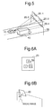
- a plurality of antennas 25 of a directional finder is deployed horizontally on a gantry 30, and the antennas 25 receive radio waves transmitted from vehicles.
- the antenna 25 is an array antenna comprising at least two antenna elements 50.
- directional lines 1 and 2 are drawn from the position of each antenna 25 based in the DOAs measured by way of the radio wave transmitted from a vehicle, and then the position of intersection of the two directional lines is determined as the location of the vehicle 10.
- a plurality of antenna elements 50 are used.
- the element numbers (natural numbers from 1 to n) are assigned to each antenna element 50.
- a signal outputted from each antenna element 50 is referred to as X1, X2, X3, ....,Xn wherein the numbers represent the element numbers respectively, and when antenna elements 50 are paired to form pairs, the phase difference ⁇ ij of each pair is represented by the following equation (1).
- ⁇ ij X i X j * ⁇
- the symbol i and j in the equation (1) represent the element numbers assigned to each antenna element 50.
- the theoretical value (or measured value) of signals received by each antenna element 50 is calculated (or measured) for all the directional angles ⁇ in the predetermined range, and the theoretical values (or measured values) are stored in a memory device.
- the theoretical values (or measured values) are represented as A1( ⁇ ), A2( ⁇ ), A3( ⁇ ), ..., An( ⁇ ) corresponding to the element numbers given to each antenna element 50.
- phase difference of each antenna element 50 pair is represented by the following equation (2).
- a ij ( ⁇ ) A i ( ⁇ ) A j * ( ⁇ ) ⁇
- the standard phase difference A ij ( ⁇ ) represented by the equation (2) is calculated previously for all the directional angles ⁇ .
- the directional angle ⁇ at which the phase difference ⁇ ij represented by the equation (1) becomes nearest the standard phase difference A ij ( ⁇ ) represented by the equation (2) is obtained, and the obtained directional angle is estimated to be the direction of arrival (DOA).
- DOA direction of arrival
- the least-square method is used for estimation of the DOA, and then the DOA ⁇ at which the following equation (3) becomes the minimum is determined.
- the DOA of the radio wave received by means of at least one pair of antennas 25 disposed horizontally on the gantry 30 as shown in Fig. 1 is determined by way of the above-mentioned one dimensional interferometry principle.
- Directional lines 1 and 2 are drawn from the position, where each antenna 25 is provided, based on the DOA of radio wave measured by means of each antenna 25 as shown in Fig. 3B.
- the intersection of the directional lines 1 and 2 drawn from each antenna 25 is detected as the location of the vehicle 10 which transmitted radio wave.
- the vehicle identification system by way of one dimensional interferometry principle tracks the locus of a vehicle by measuring one-dimensionally only the DOA of radio wave transmitted from the vehicle.
- a small vehicle 10 such as a passenger car moves side by side in parallel with a large vehicle 40 such as a trailer or a bus as shown in Fig. 4B
- radio wave from the vehicle 10 is blocked by the large vehicle 40 and does not arrive at the antenna 25 (this condition is referred to as shadowing). It is sometimes difficult to measure the location of a vehicle 10 in the case that the location is measured only by way of the DOA.
- a plurality of antennas 20 is deployed not only in horizontal direction but also in vertical direction as shown in Fig. 5.
- the directional angle and depression angle of arrival radio wave from the vehicle are measured two-dimensionally.
- the location of a vehicle is measured by way of two dimensional interferometry principle.
- At least two antennas 20 out of a plurality of antennas deployed in horizontal direction and vertical direction are selected as the antennas used for measurement of the directional angle and depression angle.
- the location of a vehicle in the vertical plane and horizontal plane is measured based on the information obtained from the selected antennas 20.
- An array antenna comprising at least three antenna elements 50 as shown in Fig. 6A is used as the antenna 20.
- the antenna 20 is installed with a depression angle of about 45 degrees toward the road to increase the radio wave sensitivity and range of measurement as shown in Fig. 6B.
- n antenna elements 50 to which the element numbers from 1 to n are given respectively are used.
- Signals outputted from each antenna element 50 are represented by X1, X2, X3, ..., Xn, wherein the numbers represent the element number respectively.
- Antenna elements 50 are paired to form pairs, and the phase difference ⁇ ij of each pair is represented by the above-mentioned equation (1).
- the theoretical value (or measured value) of a signal to be outputted from each antenna element 50 is determined previously for all the directional angle ⁇ and depression angle ⁇ , and these values are stored in a memory device.
- the theoretical value (or measured value) is represented by A1( ⁇ , ⁇ ), A2( ⁇ , ⁇ ), A3( ⁇ , ⁇ ), ..., An( ⁇ , ⁇ ) corresponding to the element number given to each antenna element 50.
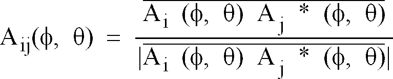
- phase difference of each pair is represented by the following equation (4).
- a ij ( ⁇ , ⁇ ) A i ( ⁇ , ⁇ ) A j * ( ⁇ , ⁇ ) ⁇
- the standard phase A ij ( ⁇ , ⁇ ) represented by the equation (4) is determined previously for all the directional angle ⁇ and depression angle ⁇ .
- the directional angle ⁇ and depression angle ⁇ at which the phase difference ⁇ ij represented by the equation (1) becomes nearest the standard phase difference A ij ( ⁇ , ⁇ ) represented by the equation (4) is determined.
- the determined directional angle ⁇ and depression angle ⁇ are estimated to be a DOA of radio wave from a vehicle.
- the least square method is used for estimation of the DOA. That is, the DOA ⁇ and ⁇ at which the equation (5) becomes the minimum are determined.
- the DOA ( ⁇ 1, ⁇ 1) and ( ⁇ 2 and ⁇ 2) of radio wave is determined.
- PA1 and PA2 are plane antennas
- ⁇ 1 and ⁇ 2 are directional angles of arriving radio wave
- ⁇ 1 and ⁇ 2 are depression angles of arriving radio wave
- b is a base line length namely a distance between PA1 and PA2
- d1 and d2 are horizontal distances from a vehicle 10 to each antenna 20
- h is a height from the vehicle 10 to the gantry 30
- H is the height of the gantry 30 to be installed.
- the installation height of the transceiver equipped with the vehicle from the ground is H-h.
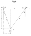
- the location on the horizontal plane of the vehicle 10 which is transmitting radio wave is represented by coordinates X and Y having the origin at the location of the antenna 20 as shown in Fig. 8.
- the location X and Y of the vehicle 10 on the horizontal plane is determined by way of the following equations (6) to (10) using the measured DOA (directional angle and depression angle) of radio wave and the known base line length.
- (6) d 1 bcos ⁇ 2 sin( ⁇ 1 + ⁇ 2 ) (7)
- d 2 bcos ⁇ 1 sin( ⁇ 1 + ⁇ 2 ) (8)
- X d 1 sin ⁇ 1 (10)
- Y d 1 cos ⁇ 1
- At least two antennas which are estimated to be positioned at the place where the antennas can receive radio wave from the vehicle without blocking of radio wave by a large vehicle 40 are selected out of a plurality of antennas deployed.
- the locus of the DOA of radio wave measured for each antenna are traced, and most suitable antennas 20 are selected, that is, antennas deviated significantly from the average locus are not selected,
- antennas 20 are measured by way of two dimensional interferometry principle, it is possible to deploy antennas 20 not only in horizontal direction but also in vertical direction.
- the optimal combination of antennas 20 which receive radio wave without blocking by a large vehicle is selected, and thus the adverse effect of shadowing is suppressed.
- combinations of antennas such as antenna 20-1 and antenna 20-2, and antenna 20-1 and antenna 20-3 corresponds such optimal combination.
- the location of a vehicle is calculated both for the horizontal plane and vertical plane based on the directional angle and depression angle of arriving radio wave from the vehicle, the location of the vehicle is measured therefore more accurately.
- a vehicle 10 is provided with an IC card decoder 60 for analyzing an IC card on which information for identifying the vehicle is recorded and a transceiver 70 for transmitting an ID code signal analyzed by the decoder 60 by way of radio wave.
- the information such as the vehicle number, name of owner of the vehicle, and specified bank account number is recorded previously.
- the vehicle identification system at least four antennas 20 disposed in horizontal and vertical direction namely two dimensionally as shown in Fig. 4A, each antenna has at least three antenna elements 50 as shown in Fig. 6A, and receives the ID code signal transmitted from the vehicle 10.
- the plurality of antennas 20 receives radio wave (ID code signal) including the ID code transmitted from the transceiver 70 of the vehicle 10.
- the location of the vehicle 10 which transmitted radio wave is measured using the radio wave received by two antennas 20 which are selected by an antenna selector 100.
- the antenna selector 100 selects at least two antennas which are estimated to receive sufficiently radio wave from the vehicle without blocking of radio wave by a large vehicle as described hereinbefore. Alternately, the antenna selector 100 traces the locus of the DOA of radio wave measured by each antenna 20, rejects antennas with significant deviation from the average locus, and selects at least two optimal antennas 20 (S101).
- the radio wave namely ID code signal received by two antennas 20 selected by the antenna selector 100 is analyzed by a signal analyzer 110, and the vehicle 10 which transmitted the ID code signal is specified based on the analysis result of the signal analyzer 110 (S102).
- the directional angle ⁇ and depression angle ⁇ namely the DOA of the radio wave received by the antennas 20 are determined by a direction detector (directional finder) 120 (S103).
- the antenna selector 100 selects the antennas 20-1 and 20-2 shown in Fig. 5
- the directional angle and depression angle of the arriving radio wave received by the antennas 20-1 and 20-2 namely ( ⁇ 1, ⁇ 1) and ( ⁇ 2, ⁇ 2) shown in Fig. 7, are determined as the DOA by the direction detector 120.
- a location detector 130 calculates the location of the vehicle 10 both on the horizontal plane and vertical plane based on the DOA measured by the direction detector 120 (S104).
- the processing performed by the direction detector 120 and location detector 130 is operated by way of two dimensional interferometry principle.
- the size of the vehicle 10 may be estimated based on the height information of the vehicle 10 calculated by the location detector 130.
- a vehicle tracking unit 140 stores correspondingly a locus data of the vehicle 10 obtained by tracking the location data of the vehicle 10 obtained by the location detector 130 and the ID data for identifying the vehicle 10 obtained by the signal analyzer 110 in a memory device not shown in the figure.
- the movement of the vehicle 10 is tracked by the vehicle tracking unit 140 (S105).
- the tracking processing by the vehicle tracking unit 140 is realized by storing successively location data in the memory device while location data of the vehicle 10 obtained every certain time interval from the location detector 130 are correlated for each location change by way of correlation processing.
- a video camera 150 that is a picture data collection means takes a picture of the toll collection area, and the picture data which includes the picture of the vehicle 10 which is coming in the area is collected.
- a data correlating unit 160 correlates the locus data of the vehicle 10 supplied from the vehicle tracking unit 140 with the picture data supplied from the video camera 150 (S106).
- the vehicle number that is the information for specifying the vehicle 10 included in the locus data is correlated with the vehicle number obtained from the picture taken by the video camera 150. The identification whether the vehicle 10 which had the IC card and transmitted the ID code signal is exactly the same as the vehicle 10 on the picture taken by the video camera 150 is judged.
- the data correlation unit 160 supplies the correlation result and locus data including the ID for specifying the vehicle 10 to a controller 170.
- the controller 170 collects automatically a prescribed toll from the vehicle 10 which comes in the toll collection area based on the data supplied from the data correlation unit 160.
- the toll is collected by automatic withdrawing of the prescribed amount for the toll from the specified bank account registered in the IC card.
- the controller 170 judges whether the vehicle 10 is a violator vehicle based on the locus data supplied from the data correlation unit 160 (S107). If the data correlation unit 160 finds an incomplete or unjust ID data, or conflict between the vehicle number included in the ID data and the vehicle number on the picture taken by the video camera 150, the controller 170 judges the vehicle 10 to be a violator vehicle.
- the controller 170 determines the vehicle 10 to be a violator vehicle
- the controller 170 sends the data of the vehicle 10 namely the locus data acquired by the vehicle tracking unit 140 and picture data acquired by the video camera 150 to the central controller 180 for registering (S108).
- the vehicle and owner of the vehicle are specified based on the locus and picture data, and a prescribed toll is collected later.
- the controller 170 controls the antenna selector 100, signal analyzer 110, direction detector 120, location detector 130, vehicle tracking unit 140, and data correlation unit 160 at desired timing.
- the DOA of radio wave transmitted from a vehicle is measured two-dimensionally based on the directional angle and depression angle, the vehicle location is measured both on the horizontal plane and vertical plane.
- the location of a vehicle which comes in the certain area is detected accurately.
- the adverse effect of shadowing can be suppressed, and therefore miss detection of a vehicle is prevented.
- antennas can be disposed not only in the horizontal direction but also in the vertical direction, and the optimal antennas can be selected so that the adverse blocking effect of radio wave by a large vehicle such as a trailer or a bus is eliminated.
- the size of a vehicle may be estimated based on the height information of the vehicle, and thus the vehicle is detected and identified easily.
Landscapes
- Physics & Mathematics (AREA)
- General Physics & Mathematics (AREA)
- Engineering & Computer Science (AREA)
- Computer Networks & Wireless Communication (AREA)
- Business, Economics & Management (AREA)
- Finance (AREA)
- Devices For Checking Fares Or Tickets At Control Points (AREA)
- Traffic Control Systems (AREA)
- Position Fixing By Use Of Radio Waves (AREA)
- Radar Systems Or Details Thereof (AREA)
- Optical Radar Systems And Details Thereof (AREA)
Abstract
Description
- This invention relates to a vehicle identification system, and particularly relates to a vehicle identification system applicable to the electric toll collection (ETC) systems provided with a means for measuring the location of a vehicle by measuring direction of arrival (DOA) of radio wave transmitted from the vehicle.
- A conventional vehicle identification system to be applied to ETC systems for using on toll roads is disclosed in USP 5,440, 109. In this conventional vehicle identification system, an infrared beacon (IRB) which is a component of an infrared communication system (IRK), an infrared video camera (IRV) which is a component of an infrared location measurement system, a traffic radar system (RD), and a usual video camera (NV) which is a component of a vehicle identification-recording system (FIR) are installed on a toll booth side. These systems are connected to a controller for performing a total data processing and correlative processing.
- By way of the data fusion of three types of information obtained from these systems, namely radar information, IR location information, and video information, the identification of a vehicle under the communication for toll collection is performed.
- However, in this conventional vehicle identification system, it is required to install an infrared communication system, and it results in high cost. The communication by way of infrared ray is not appropriate to a foggy environment, and therefore if this conventional vehicle identification system is used in a foggy place, it is apt to cause the erroneous detection of a vehicle and communication trouble between a toll booth and vehicles.
- It is an object of the present invention to provide a vehicle identification system which is excellent in reliability and can be manufactured at a low cost.
- It is another object of the present invention to provide a vehicle identification system which is capable of identifying individually a plurality of vehicles accurately regardless of overlapping of the plurality of vehicles disposed side by side in parallel.
- To achieve the above-mentioned objects, the system for identifying a vehicle which comes in a prescribed area in accordance with the present invention is provided with a receiving means for receiving radio wave transmitted from the vehicle which comes in the prescribed area, an identification means for identifying the vehicle based on the ID signal included in said radio wave which is received by said receiving means, a directional finder for measuring the direction of arrival of the radio wave, and a location detection means for calculating the location of the vehicle based on the direction of arrival measured by the directional finder.
- The vehicle identification system in accordance with the present invention is provided with a means for measuring the direction of arrival of radio wave transmitted from the vehicle which comes in the prescribed area by way of two dimensional interferometry principle in terms of the directional angle and depression angle.
- The system for identifying the vehicle which comes in the toll collection area and for collecting a prescribed toll from the vehicle in accordance with the present invention is provided with a receiving means for receiving radio wave transmitted from a vehicle which comes in a toll collection area, an identification means for identifying the vehicle by analyzing the ID signal included in the received radio wave, a directional finder for measuring the direction of arrival of the radio wave, a location detection means for calculating the location of the vehicle based on the direction of arrival measured by the directional finder, a vehicle tracking means for calculating the locus of the vehicle based on the identification information of the vehicle outputted from the identification means and the location information of the vehicle outputted from the location detection means, a camera means for taking a picture of the vehicle and outputting a picture data, and a toll collection means for collecting a desired toll from the vehicle based on the locus data supplied from the vehicle tracking means and the picture data supplied from the camera means.
- The above and other objects, features and advantages of the present invention will become more apparent from the following detailed description taken with the accompanying drawings in which:
- Fig. 1 is a perspective view for illustrating the structure of a vehicle identification system applying a one dimensional interferometry principle,
- Fig. 2 is a diagram for illustrating an antenna shown in Fig. 1,
- Fig. 3A is a perspective view for describing a method for detecting a vehicle applying the one dimensional interferometry principle,
- Fig. 3B is a plan view of Fig. 3A,
- Fig. 4A is a perspective view for illustrating the structure of a vehicle identification system applying a two dimensional interferometry principle in accordance with the present invention,
- Fig. 4B is a diagram for illustrating an example of inaccurate measurement of direction by means of a vehicle identification system applying the one dimensional interferometry principle,
- Fig. 5 is a perspective view for illustrating the structure of a vehicle identification system of an embodiment applying the two dimensional interferometry principle in accordance with the present invention,
- Fig. 6A is a diagram for illustrating the structure of a antenna shown in Fig. 5,
- Fig. 6B is a diagram for illustrating the set angle of the antenna shown in Fig. 5,
- Fig. 7 is a perspective view for describing the location measurement method of a vehicle applying the two dimensional interferometry principle in the embodiment in accordance with the present invention,
- Fig. 8 is a plan view for describing the on-plane location measurement method of a vehicle applying the two dimensional interferometry principle in the embodiment in accordance with the present invention,
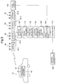
- Fig. 9 is a schematic diagram for illustrating the structure of a vehicle identification system of the embodiment in accordance with the present invention, and
- Fig. 10 is a flow chart for describing the processing sequence in the vehicle identification system shown in Fig. 9.
- One embodiment of a vehicle identification system in accordance with the present invention will be described in detail referring to the drawings.
- The vehicle identification system of the embodiment identifies vehicles applying two-dimensional interferometry principle.
- Firstly, before the vehicle identification system applying the two-dimensional interferometry principle is explained, the method of measuring the location of the vehicle applying one-dimensional interferometry principle will be described referring to the Fig.1 and 2.
- In Fig. 1, a plurality of
antennas 25 of a directional finder is deployed horizontally on agantry 30, and theantennas 25 receive radio waves transmitted from vehicles. Theantenna 25 is an array antenna comprising at least twoantenna elements 50. In the location measurement method by way of one dimensional interferometry principle, as shown in Figs. 3A and 3B,directional lines antenna 25 based in the DOAs measured by way of the radio wave transmitted from a vehicle, and then the position of intersection of the two directional lines is determined as the location of thevehicle 10. - The position measurement method by way of one dimensional interferometry principle is described herein under in detail.
- A plurality of
antenna elements 50, the number of which are n (n=1,2, ...), are used. The element numbers (natural numbers from 1 to n) are assigned to eachantenna element 50. A signal outputted from eachantenna element 50 is referred to as X1, X2, X3, ....,Xn wherein the numbers represent the element numbers respectively, and whenantenna elements 50 are paired to form pairs, the phase difference ψij of each pair is represented by the following equation (1).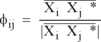
- Here, the symbol i and j in the equation (1) represent the element numbers assigned to each
antenna element 50. - Previously, the theoretical value (or measured value) of signals received by each
antenna element 50 is calculated (or measured) for all the directional angles φ in the predetermined range, and the theoretical values (or measured values) are stored in a memory device. The theoretical values (or measured values) are represented as A1(φ), A2(φ), A3(φ), ..., An(φ) corresponding to the element numbers given to eachantenna element 50. - Like the equation (1), the phase difference of each
antenna element 50 pair is represented by the following equation (2).
- The standard phase difference Aij(φ) represented by the equation (2) is calculated previously for all the directional angles φ. The directional angle φ at which the phase difference ψij represented by the equation (1) becomes nearest the standard phase difference Aij(φ) represented by the equation (2) is obtained, and the obtained directional angle is estimated to be the direction of arrival (DOA). The least-square method is used for estimation of the DOA, and then the DOA φ at which the following equation (3) becomes the minimum is determined.

- Next, a method for determining a vehicle location based on the DOA is described.
- The DOA of the radio wave received by means of at least one pair of
antennas 25 disposed horizontally on thegantry 30 as shown in Fig. 1 is determined by way of the above-mentioned one dimensional interferometry principle.Directional lines antenna 25 is provided, based on the DOA of radio wave measured by means of eachantenna 25 as shown in Fig. 3B. The intersection of thedirectional lines antenna 25 is detected as the location of thevehicle 10 which transmitted radio wave. - However, the vehicle identification system by way of one dimensional interferometry principle tracks the locus of a vehicle by measuring one-dimensionally only the DOA of radio wave transmitted from the vehicle. When a
small vehicle 10 such as a passenger car moves side by side in parallel with alarge vehicle 40 such as a trailer or a bus as shown in Fig. 4B, radio wave from thevehicle 10 is blocked by thelarge vehicle 40 and does not arrive at the antenna 25 (this condition is referred to as shadowing). It is sometimes difficult to measure the location of avehicle 10 in the case that the location is measured only by way of the DOA. - In this case, though the location of a vehicle is measured based on the intersection of a pair of directional lines from a pair of
antennas 25 as shown in Fig. 3A, in the one dimensional interferometry principle, the intersection of directional lines is not deviate from the true position because of insufficient information in vertical direction due to depression angle, this insufficient information adversely affects the location error. - Now, a vehicle identification system in accordance with the preferred embodiment of the present invention will be described as follows.
- In a vehicle identification system in accordance with the preferred embodiment of the present invention, a plurality of
antennas 20 is deployed not only in horizontal direction but also in vertical direction as shown in Fig. 5. The directional angle and depression angle of arrival radio wave from the vehicle are measured two-dimensionally. In other words, the location of a vehicle is measured by way of two dimensional interferometry principle. At least twoantennas 20 out of a plurality of antennas deployed in horizontal direction and vertical direction are selected as the antennas used for measurement of the directional angle and depression angle. The location of a vehicle in the vertical plane and horizontal plane is measured based on the information obtained from the selectedantennas 20. An array antenna comprising at least threeantenna elements 50 as shown in Fig. 6A is used as theantenna 20. Theantenna 20 is installed with a depression angle of about 45 degrees toward the road to increase the radio wave sensitivity and range of measurement as shown in Fig. 6B. - Next, a method for determining the directional angle and depression angle of arriving radio wave from a vehicle by way of two dimensional interferometry principle is described hereinafter.
- In the two dimensional interferometry principle like one dimensional interferometry principle,
n antenna elements 50 to which the element numbers from 1 to n are given respectively are used. Signals outputted from eachantenna element 50 are represented by X1, X2, X3, ..., Xn, wherein the numbers represent the element number respectively.Antenna elements 50 are paired to form pairs, and the phase difference ψij of each pair is represented by the above-mentioned equation (1). The theoretical value (or measured value) of a signal to be outputted from eachantenna element 50 is determined previously for all the directional angle θ and depression angle φ, and these values are stored in a memory device. The theoretical value (or measured value) is represented by A1(φ, θ), A2(φ, θ), A3(φ, θ), ..., An(φ, θ) corresponding to the element number given to eachantenna element 50. - Like the equation (1), the phase difference of each pair is represented by the following equation (4).
- The standard phase Aij(φ, θ) represented by the equation (4) is determined previously for all the directional angle φ and depression angle θ. The directional angle φ and depression angle θ at which the phase difference ψij represented by the equation (1) becomes nearest the standard phase difference Aij (φ, θ) represented by the equation (4) is determined. The determined directional angle φ and depression angle θ are estimated to be a DOA of radio wave from a vehicle. The least square method is used for estimation of the DOA. That is, the DOA φ and θ at which the equation (5) becomes the minimum are determined.

- Next, a method for determining the location of a vehicle based on the DOA of radio wave from the vehicle as described herein above is described hereinafter.
- In the case that two
antennas 20 are used for measuring the DOA of radio wave as shown in Fig. 7, the DOA (φ1, θ1) and (φ2 and θ2) of radio wave is determined. In Fig. 7, PA1 and PA2 are plane antennas, θ1 and θ2 are directional angles of arriving radio wave, φ1 and φ2 are depression angles of arriving radio wave, b is a base line length namely a distance between PA1 and PA2, d1 and d2 are horizontal distances from avehicle 10 to eachantenna 20, h is a height from thevehicle 10 to thegantry 30, and H is the height of thegantry 30 to be installed. The installation height of the transceiver equipped with the vehicle from the ground is H-h. - The location on the horizontal plane of the
vehicle 10 which is transmitting radio wave is represented by coordinates X and Y having the origin at the location of theantenna 20 as shown in Fig. 8. The location X and Y of thevehicle 10 on the horizontal plane is determined by way of the following equations (6) to (10) using the measured DOA (directional angle and depression angle) of radio wave and the known base line length.
- Further, for measurement of the location of the
vehicle 10, at least two antennas which are estimated to be positioned at the place where the antennas can receive radio wave from the vehicle without blocking of radio wave by alarge vehicle 40 are selected out of a plurality of antennas deployed. Alternately, the locus of the DOA of radio wave measured for each antenna are traced, and mostsuitable antennas 20 are selected, that is, antennas deviated significantly from the average locus are not selected, - In this embodiment, because the directional angle and depression angle of arriving radio wave are measured by way of two dimensional interferometry principle, it is possible to deploy
antennas 20 not only in horizontal direction but also in vertical direction. When the location of a vehicle which is transmitting radio wave is measured, the optimal combination ofantennas 20 which receive radio wave without blocking by a large vehicle is selected, and thus the adverse effect of shadowing is suppressed. In Fig. 5, combinations of antennas such as antenna 20-1 and antenna 20-2, and antenna 20-1 and antenna 20-3 corresponds such optimal combination. - The location of a vehicle is calculated both for the horizontal plane and vertical plane based on the directional angle and depression angle of arriving radio wave from the vehicle, the location of the vehicle is measured therefore more accurately.
- Next, a vehicle identification system of the embodiment of the present invention to which the above-mentioned method for measuring the location of a vehicle is applied is described referring to the drawings. In particular, an embodiment in which the vehicle identification system is applied to collect toll on a high way, for example, is described.
- In Fig. 9, a
vehicle 10 is provided with anIC card decoder 60 for analyzing an IC card on which information for identifying the vehicle is recorded and atransceiver 70 for transmitting an ID code signal analyzed by thedecoder 60 by way of radio wave. In the IC card, the information such as the vehicle number, name of owner of the vehicle, and specified bank account number is recorded previously. On the other hand, in the vehicle identification system, at least fourantennas 20 disposed in horizontal and vertical direction namely two dimensionally as shown in Fig. 4A, each antenna has at least threeantenna elements 50 as shown in Fig. 6A, and receives the ID code signal transmitted from thevehicle 10. In detail, when thevehicle 10 comes in the toll collection area of a toll road such as a high way, the plurality ofantennas 20 receives radio wave (ID code signal) including the ID code transmitted from thetransceiver 70 of thevehicle 10. - The location of the
vehicle 10 which transmitted radio wave is measured using the radio wave received by twoantennas 20 which are selected by anantenna selector 100. Theantenna selector 100 selects at least two antennas which are estimated to receive sufficiently radio wave from the vehicle without blocking of radio wave by a large vehicle as described hereinbefore. Alternately, theantenna selector 100 traces the locus of the DOA of radio wave measured by eachantenna 20, rejects antennas with significant deviation from the average locus, and selects at least two optimal antennas 20 (S101). - The radio wave namely ID code signal received by two
antennas 20 selected by theantenna selector 100 is analyzed by asignal analyzer 110, and thevehicle 10 which transmitted the ID code signal is specified based on the analysis result of the signal analyzer 110 (S102). - Next, the directional angle θ and depression angle φ namely the DOA of the radio wave received by the
antennas 20 are determined by a direction detector (directional finder) 120 (S103). Assuming that theantenna selector 100 selects the antennas 20-1 and 20-2 shown in Fig. 5, the directional angle and depression angle of the arriving radio wave received by the antennas 20-1 and 20-2, namely (φ1, θ1) and (φ2, θ 2) shown in Fig. 7, are determined as the DOA by thedirection detector 120. Alocation detector 130 calculates the location of thevehicle 10 both on the horizontal plane and vertical plane based on the DOA measured by the direction detector 120 (S104). The processing performed by thedirection detector 120 andlocation detector 130 is operated by way of two dimensional interferometry principle. The size of thevehicle 10 may be estimated based on the height information of thevehicle 10 calculated by thelocation detector 130. - A
vehicle tracking unit 140 stores correspondingly a locus data of thevehicle 10 obtained by tracking the location data of thevehicle 10 obtained by thelocation detector 130 and the ID data for identifying thevehicle 10 obtained by thesignal analyzer 110 in a memory device not shown in the figure. In other words, the movement of thevehicle 10 is tracked by the vehicle tracking unit 140 (S105). The tracking processing by thevehicle tracking unit 140 is realized by storing successively location data in the memory device while location data of thevehicle 10 obtained every certain time interval from thelocation detector 130 are correlated for each location change by way of correlation processing. - Simultaneously with the processing for acquiring the locus data of the
vehicle 10 described herein above, avideo camera 150 that is a picture data collection means takes a picture of the toll collection area, and the picture data which includes the picture of thevehicle 10 which is coming in the area is collected. Adata correlating unit 160 correlates the locus data of thevehicle 10 supplied from thevehicle tracking unit 140 with the picture data supplied from the video camera 150 (S106). In detail, the vehicle number that is the information for specifying thevehicle 10 included in the locus data is correlated with the vehicle number obtained from the picture taken by thevideo camera 150. The identification whether thevehicle 10 which had the IC card and transmitted the ID code signal is exactly the same as thevehicle 10 on the picture taken by thevideo camera 150 is judged. - The
data correlation unit 160 supplies the correlation result and locus data including the ID for specifying thevehicle 10 to acontroller 170. Thecontroller 170 collects automatically a prescribed toll from thevehicle 10 which comes in the toll collection area based on the data supplied from thedata correlation unit 160. The toll is collected by automatic withdrawing of the prescribed amount for the toll from the specified bank account registered in the IC card. At the same time, thecontroller 170 judges whether thevehicle 10 is a violator vehicle based on the locus data supplied from the data correlation unit 160 (S107). If thedata correlation unit 160 finds an incomplete or unjust ID data, or conflict between the vehicle number included in the ID data and the vehicle number on the picture taken by thevideo camera 150, thecontroller 170 judges thevehicle 10 to be a violator vehicle. - When the
controller 170 determines thevehicle 10 to be a violator vehicle, thecontroller 170 sends the data of thevehicle 10 namely the locus data acquired by thevehicle tracking unit 140 and picture data acquired by thevideo camera 150 to thecentral controller 180 for registering (S108). For thevehicle 10 registered as a violator vehicle in thecentral controller 180, the vehicle and owner of the vehicle are specified based on the locus and picture data, and a prescribed toll is collected later. - On the other hand, the data of the
vehicle 10 which is judged not to be a violator vehicle by thecontroller 170 and from which a prescribed toll is collected, namely the locus data and picture data, is erased (S109). - The
controller 170 controls theantenna selector 100,signal analyzer 110,direction detector 120,location detector 130,vehicle tracking unit 140, anddata correlation unit 160 at desired timing. - According to the present invention, since the DOA of radio wave transmitted from a vehicle is measured two-dimensionally based on the directional angle and depression angle, the vehicle location is measured both on the horizontal plane and vertical plane. The location of a vehicle which comes in the certain area is detected accurately. In particular, the adverse effect of shadowing can be suppressed, and therefore miss detection of a vehicle is prevented.
- In the location measurement by way of two dimensional interferometry principle, antennas can be disposed not only in the horizontal direction but also in the vertical direction, and the optimal antennas can be selected so that the adverse blocking effect of radio wave by a large vehicle such as a trailer or a bus is eliminated.
- Further, the size of a vehicle may be estimated based on the height information of the vehicle, and thus the vehicle is detected and identified easily.
- It is apparent that the present invention is not limited to the above embodiment but may be modified and changed without departing from the scope and spirit of the present invention.
Claims (20)
- A system for identifying a vehicle which comes in a prescribed area, characterized in that comprising;a receiving means (20) for receiving radio wave transmitted from a vehicle (10) which comes in a prescribed area,an identification means (110) for identifying said vehicle based on an ID signal included in said radio wave which is received by said receiving means,a directional finder (120) for measuring a direction of arrival of said radio wave, anda location detection means (130) for calculating a location of said vehicle based on the direction of arrival measured by said directional finder.
- The system as claimed in claim 1, wherein said receiving means is provided with a plurality of antennas (20-1, 20-2, 20-3 and 20-4), each antenna has at least three antenna elements (50), and said directional finder is provided with a means for measuring a directional angle and depression angle of said radio wave to each antenna based on phase difference of said radio wave received by said two antenna elements included in said respective antennas and previously registered standard phase difference.
- The system as claimed in claim 1 or 2, wherein said location detection means determines an intersection of direction lines formed from each antenna as the location of said vehicle in a horizontal direction, said direction lines formed in the direction of arrival of said radio wave received by said respective antennas from said respective antennas.
- The system as claimed in claim 2 or 3, wherein said plurality of antennas is disposed in the horizontal direction and vertical direction respectively.
- The system as claimed in claim 2 or 3, wherein said plurality of antennas comprises at least two antennas disposed in the horizontal direction and at least two antennas disposed in the vertical direction.
- The system as claimed in any of claims 2 to 5, further comprising:a selector (100) for selecting at least two antennas which are receiving normally radio wave transmitted from said vehicle; and
wherein said directional finder measures the direction of arrival of said radio wave received by at least two antennas selected by said selection means. - The system as claimed in any of claims 2 to 6, wherein said antenna is disposed with its radio wave receiving plane facing in the inclined depressing direction.
- The system as claimed in any of claims 1 to 7, further comprising:a vehicle tracking means (140) for determining the locus of said vehicle based on the location of said vehicle measured by said location detection means.
- The system as claimed in any of claims 1 to 8, further comprising:a camera means (150) for taking a picture of said vehicle which comes in said prescribed area.
- The system as claimed in claim 8, further comprising:a camera means (150) for taking a picture of said vehicle which comes in said prescribed area and outputting a picture data; anda means (160) for identifying said vehicle by correlating said picture data supplied from said camera means with the locus of said vehicle determined by said vehicle tracking means.
- The system as claimed in any of claims 1 to 10, wherein said directional finder measures the direction of arrival of radio wave transmitted from said vehicle by way of two dimensional interferometry principle in terms of a directional angle and depression angle.
- The system as claimed in claim 11, wherein said location detection means calculates the location of said vehicle on the horizontal plane and the height in the vertical direction based on the directional angle and depression angle of the directional of arrival of the radio wave measured by said directional finder.
- A system for identifying a vehicle which comes in a toll collection area and for collecting a prescribed toll from said vehicle, characterized in that comprising;a receiving means (20) for receiving radio wave transmitted from a vehicle (10) which comes in a toll collection area,an identification means (110) for identifying said vehicle by analyzing an ID signal included in said received radio wave,a directional finder (120) for measuring a direction of arrival of said radio wave,a location detection means (130) for calculating the location of said vehicle based on the direction of arrival measured by said directional finder,a vehicle tracking means (140) for calculating the locus of said vehicle based on an identification information of said vehicle outputted from said identification means and a location information of said vehicle outputted from said location detection means, and outputting locus data indicative of the locus of said vehicle,a camera means (150) for taking a picture of said vehicle and outputting a picture data, anda toll collection means (170) for collecting a desired toll from said vehicle based on the locus data outputted from said vehicle tracking means and the picture data outputted from said camera means.
- The system as claimed in claim 13, further comprising:a correlation means (160) for correlating said locus data with the said picture data; anda judging means (170) for judging whether said vehicle is a violator vehicle based on correlation result generated by said correlation means.
- The system as claimed in claim 13 or 14, further comprising:a means (170, 180) for registering the locus data and picture data of said vehicle when said vehicle is judged to be a violator vehicle.
- The system as claimed in any of claims 13 to 15, further comprising:a means (170) for erasing the locus data and picture data of said vehicle when said vehicle is judged not to be a violator vehicle.
- The system as claimed in any of claims 13 to 16, wherein said receiving means is provided with a plurality of antennas (20-1, 20-2, 20-3, 20-4) having at least three antenna elements (50), and said directional finder is provided with a means for measuring the direction of arrival of said radio wave to each antenna based on phase difference of said radio wave received by said two antenna elements included in said respective antennas and previously registered standard phase difference.
- The system as claimed in any of claims 13 to 17, wherein said directional finder measures the direction of arrival of radio wave transmitted from said vehicle by way of two dimensional interferometry principle in terms of the directional angle and depression angle.
- The system as claimed in any of claims 13 to 18, wherein said location detection means calculates the location of said vehicle on the horizontal plane and the height in the vertical direction based on the directional angle and depression angle of the direction of arrival of the radio wave measured by said directional finder.
- The system as claimed in any of claims 14 to 19, said correlation means is provided with a means for correlating vehicle number information of said vehicle included in said ID signal with vehicle number information on the picture taken by said camera means.
Applications Claiming Priority (3)
| Application Number | Priority Date | Filing Date | Title |
|---|---|---|---|
| JP9276596 | 1996-04-15 | ||
| JP92765/96 | 1996-04-15 | ||
| JP9276596A JP2918024B2 (en) | 1996-04-15 | 1996-04-15 | Vehicle trajectory tracking device |
Publications (2)
| Publication Number | Publication Date |
|---|---|
| EP0802515A1 true EP0802515A1 (en) | 1997-10-22 |
| EP0802515B1 EP0802515B1 (en) | 2001-10-24 |
Family
ID=14063529
Family Applications (1)
| Application Number | Title | Priority Date | Filing Date |
|---|---|---|---|
| EP19970106105 Expired - Lifetime EP0802515B1 (en) | 1996-04-15 | 1997-04-14 | Vehicle identification system for electric toll collection system |
Country Status (6)
| Country | Link |
|---|---|
| US (1) | US5969641A (en) |
| EP (1) | EP0802515B1 (en) |
| JP (1) | JP2918024B2 (en) |
| AU (1) | AU713387B2 (en) |
| CA (1) | CA2202575C (en) |
| DE (1) | DE69707548T2 (en) |
Cited By (6)
| Publication number | Priority date | Publication date | Assignee | Title |
|---|---|---|---|---|
| NL1012907C2 (en) * | 1999-08-25 | 2001-02-27 | Amb It Holding Bv | System for determining the position of a transponder. |
| WO2006101442A1 (en) | 2005-03-22 | 2006-09-28 | Kapsch Trafficom Ab | A system for use in stations for road tolls |
| WO2014200584A3 (en) * | 2013-03-15 | 2015-04-09 | Raytheon Company | Associating signal intelligence to objects via residual reduction |
| CN106304031A (en) * | 2015-05-30 | 2017-01-04 | 北京智谷睿拓技术服务有限公司 | Motion state of mobile terminal determines method and determines device |
| US10579887B2 (en) | 2017-12-01 | 2020-03-03 | At&T Intellectual Property I, L.P. | Identification using mobile device signatures and cameras |
| GB2537507B (en) * | 2013-10-23 | 2020-08-19 | Mitsubishi Heavy Ind Mach Systems Ltd | Vehicle detection device, lane control system, vehicle detection method, and program |
Families Citing this family (29)
| Publication number | Priority date | Publication date | Assignee | Title |
|---|---|---|---|---|
| SE511067C2 (en) * | 1996-10-03 | 1999-07-26 | Combitech Traffic Syst Ab | Method and apparatus for registration in a toll of the external characteristics of a vehicle |
| JPH11120396A (en) * | 1997-10-17 | 1999-04-30 | Nec Corp | Device and method for deciding communicating vehicle |
| JP3233088B2 (en) * | 1998-01-22 | 2001-11-26 | 松下電器産業株式会社 | Directivity control antenna device |
| JP3782242B2 (en) * | 1998-08-28 | 2006-06-07 | 株式会社東芝 | Toll collection system, in-vehicle device and toll collection method |
| JP2000315268A (en) * | 1999-04-30 | 2000-11-14 | Toshiba Corp | Toll collection device and toll collection method |
| JP2001036545A (en) * | 1999-05-17 | 2001-02-09 | Sony Corp | Information processing apparatus and method, information processing system, and medium |
| JP3641572B2 (en) * | 2000-03-31 | 2005-04-20 | 三菱電機株式会社 | Onboard equipment for ETC information communication control |
| US6339384B1 (en) | 2000-11-13 | 2002-01-15 | Robert Valdes-Rodriguez | Toll booth credit device |
| GB2372924A (en) * | 2001-02-22 | 2002-09-04 | Hewlett Packard Co | Networked electronic whiteboard |
| JP3666406B2 (en) * | 2001-04-04 | 2005-06-29 | 日本電気株式会社 | Non-stop fee billing method and system |
| JP4357137B2 (en) * | 2001-05-11 | 2009-11-04 | 富士通マイクロエレクトロニクス株式会社 | Mobile object tracking method and system |
| US20040083130A1 (en) * | 2002-10-03 | 2004-04-29 | Arthur Posner | Electronic toll collection system and method for rental and leased vehicles |
| US7080778B1 (en) | 2004-07-26 | 2006-07-25 | Advermotion, Inc. | Moveable object accountability system |
| JP4660300B2 (en) * | 2005-07-04 | 2011-03-30 | 株式会社東芝 | Radio wave emission source detection device |
| JP4907910B2 (en) * | 2005-07-04 | 2012-04-04 | 株式会社東芝 | Radio wave emission source detection device |
| US9076331B2 (en) * | 2007-07-16 | 2015-07-07 | Crucs Holdings, Llc | System and method to monitor vehicles on a roadway and to control driving restrictions of vehicle drivers |
| US8868220B2 (en) * | 2007-07-16 | 2014-10-21 | Crucs Holdings, Llc | Systems and methods for automatically changing operational states of appliances |
| US8432296B2 (en) * | 2009-08-14 | 2013-04-30 | Continental Automotive Systems, Inc. | System and method for deterring vehicle theft and managing vehicle parking |
| TWI464708B (en) * | 2009-09-07 | 2014-12-11 | Fci Inc | Electrical toll collection system with terminal limiting communication zone |
| WO2013080570A1 (en) * | 2011-12-02 | 2013-06-06 | パナソニック株式会社 | Radar device |
| CN102565758B (en) * | 2011-12-09 | 2013-11-27 | 北京握奇数据系统有限公司 | Positioning device and method for vehicle-mounted unit in ETC (Electronic Toll Collection) system |
| JP6149374B2 (en) * | 2012-10-11 | 2017-06-21 | 中国電力株式会社 | Location system and method for locating mobile terminal |
| JP6086203B2 (en) * | 2012-12-05 | 2017-03-01 | 中国電力株式会社 | System for providing position information to moving body and position information providing method |
| PL2804013T3 (en) * | 2013-05-13 | 2015-10-30 | Kapsch Trafficcom Ag | Device for measuring the position of a vehicle or a surface thereof |
| SI2804014T1 (en) * | 2013-05-13 | 2015-09-30 | Kapsch Trafficcom Ag | Device and method for determining a characteristic of a vehicle |
| ES2541427T3 (en) * | 2013-05-13 | 2015-07-20 | Kapsch Trafficcom Ag | Procedure to measure the position of a surface of a vehicle |
| EP3021502A4 (en) * | 2013-07-12 | 2017-03-15 | Wen-Sung Lee | Intelligent home positioning system and positioning method therefor |
| CN109031193B (en) * | 2018-07-05 | 2021-04-16 | 中国人民解放军国防科技大学 | An indoor illegal signal source location system and method based on signal arrival direction |
| CN114372364B (en) * | 2022-01-05 | 2025-08-29 | 深圳大学 | Multi-sensor instantaneous vehicle detection method, system, electronic device and storage medium |
Citations (4)
| Publication number | Priority date | Publication date | Assignee | Title |
|---|---|---|---|---|
| US3924236A (en) * | 1973-11-27 | 1975-12-02 | Int Standard Electric Corp | Surveillance radar with synthetic array scan for improved angle determination |
| US4057803A (en) * | 1976-04-08 | 1977-11-08 | The United States Of America As Represented By The Secretary Of The Navy | Adaptive direction of arrival antennae system |
| US5404144A (en) * | 1994-05-04 | 1995-04-04 | The United States Of America As Represented By The Secretary Of The Navy | Simultaneous determination of incoming microwave frequency and angle-of-arrival |
| EP0715185A2 (en) * | 1994-11-30 | 1996-06-05 | Hughes Aircraft Company | Transponder detection system and method |
Family Cites Families (3)
| Publication number | Priority date | Publication date | Assignee | Title |
|---|---|---|---|---|
| DE4310580A1 (en) * | 1993-03-31 | 1994-10-06 | Siemens Ag | Automatic fee entry system |
| US5451758A (en) * | 1993-12-08 | 1995-09-19 | Jesadanont; Mongkol | Automatic non-computer network no-stop collection of expressway tolls by magnetic cards and method |
| JP3195177B2 (en) * | 1994-11-18 | 2001-08-06 | 株式会社豊田中央研究所 | Mobile object identification device |
-
1996
- 1996-04-15 JP JP9276596A patent/JP2918024B2/en not_active Expired - Fee Related
-
1997
- 1997-04-10 US US08/827,692 patent/US5969641A/en not_active Expired - Lifetime
- 1997-04-14 DE DE69707548T patent/DE69707548T2/en not_active Expired - Lifetime
- 1997-04-14 CA CA 2202575 patent/CA2202575C/en not_active Expired - Fee Related
- 1997-04-14 EP EP19970106105 patent/EP0802515B1/en not_active Expired - Lifetime
- 1997-04-14 AU AU17869/97A patent/AU713387B2/en not_active Ceased
Patent Citations (4)
| Publication number | Priority date | Publication date | Assignee | Title |
|---|---|---|---|---|
| US3924236A (en) * | 1973-11-27 | 1975-12-02 | Int Standard Electric Corp | Surveillance radar with synthetic array scan for improved angle determination |
| US4057803A (en) * | 1976-04-08 | 1977-11-08 | The United States Of America As Represented By The Secretary Of The Navy | Adaptive direction of arrival antennae system |
| US5404144A (en) * | 1994-05-04 | 1995-04-04 | The United States Of America As Represented By The Secretary Of The Navy | Simultaneous determination of incoming microwave frequency and angle-of-arrival |
| EP0715185A2 (en) * | 1994-11-30 | 1996-06-05 | Hughes Aircraft Company | Transponder detection system and method |
Non-Patent Citations (3)
| Title |
|---|
| "CREDIT-CARD-SIZED MEMORIES SMALL MEMORIES TAKE ON WIDER APPLICATIONS", EDN ELECTRICAL DESIGN NEWS, vol. 36, no. 13, 20 June 1991 (1991-06-20), pages 67, 69 - 70, XP000363643 * |
| BOOTHROYD D: "FOR WHOM THE ROAD TOLLS", NEW ELECTRONICS, vol. 28, no. 20, 28 November 1995 (1995-11-28), pages 18 - 20, XP000549167 * |
| RITTICH D ET AL: "ZUKUENFTIGE AUTOMATISCHE GEBUEHRENERFASSUNG FUER DEN STRASSENVERKEHR", NTZ NACHRICHTENTECHNISCHE ZEITSCHRIFT, vol. 46, no. 4, 1 March 1993 (1993-03-01), pages 258 - 260, 262 - 265, XP000522477 * |
Cited By (17)
| Publication number | Priority date | Publication date | Assignee | Title |
|---|---|---|---|---|
| NL1012907C2 (en) * | 1999-08-25 | 2001-02-27 | Amb It Holding Bv | System for determining the position of a transponder. |
| WO2001014905A1 (en) * | 1999-08-25 | 2001-03-01 | Amb -It Holding B.V. | System for determining the position of a transponder |
| US7006008B1 (en) | 1999-08-25 | 2006-02-28 | Amg-It Holding B.V. | System for determining the position of a transponder |
| WO2006101442A1 (en) | 2005-03-22 | 2006-09-28 | Kapsch Trafficom Ab | A system for use in stations for road tolls |
| EP1861829A4 (en) * | 2005-03-22 | 2009-11-11 | Kapsch Trafficcom Ab | SYSTEM FOR USE IN ROAD STATION STATIONS |
| US7705750B2 (en) | 2005-03-22 | 2010-04-27 | Kapsch Trafficcom Ab | System for use in stations for road tolls |
| AU2006225386B2 (en) * | 2005-03-22 | 2011-09-29 | Kapsch Trafficcom Ag | A system for use in stations for road tolls |
| EP2426647A3 (en) * | 2005-03-22 | 2012-06-27 | Kapsch TrafficCom AB | A system and a method for a road toll system |
| WO2014200584A3 (en) * | 2013-03-15 | 2015-04-09 | Raytheon Company | Associating signal intelligence to objects via residual reduction |
| US9297654B2 (en) | 2013-03-15 | 2016-03-29 | Raytheon Company | Associating signal intelligence to objects via residual reduction |
| US9297655B2 (en) | 2013-03-15 | 2016-03-29 | Raytheon Company | Associating signal intelligence to objects via residual reduction |
| US10024661B2 (en) | 2013-03-15 | 2018-07-17 | Raytheon Company | Associating signal intelligence to objects via residual reduction |
| GB2537507B (en) * | 2013-10-23 | 2020-08-19 | Mitsubishi Heavy Ind Mach Systems Ltd | Vehicle detection device, lane control system, vehicle detection method, and program |
| CN106304031A (en) * | 2015-05-30 | 2017-01-04 | 北京智谷睿拓技术服务有限公司 | Motion state of mobile terminal determines method and determines device |
| CN106304031B (en) * | 2015-05-30 | 2019-07-09 | 北京智谷睿拓技术服务有限公司 | Motion state of mobile terminal determines method and determining device |
| US10579887B2 (en) | 2017-12-01 | 2020-03-03 | At&T Intellectual Property I, L.P. | Identification using mobile device signatures and cameras |
| US11250278B2 (en) | 2017-12-01 | 2022-02-15 | At&T Intellectual Property I, L.P. | Identification using mobile device signatures and cameras |
Also Published As
| Publication number | Publication date |
|---|---|
| JPH09282505A (en) | 1997-10-31 |
| US5969641A (en) | 1999-10-19 |
| EP0802515B1 (en) | 2001-10-24 |
| CA2202575A1 (en) | 1997-10-15 |
| DE69707548D1 (en) | 2001-11-29 |
| JP2918024B2 (en) | 1999-07-12 |
| AU1786997A (en) | 1997-10-23 |
| AU713387B2 (en) | 1999-12-02 |
| CA2202575C (en) | 2001-01-23 |
| DE69707548T2 (en) | 2002-05-08 |
Similar Documents
| Publication | Publication Date | Title |
|---|---|---|
| US5969641A (en) | Vehicle identification system for electric toll collection system | |
| EP0580139B1 (en) | Transponder location and tracking system and method | |
| EP1610258B1 (en) | RFID communication apparatus with tag position detection means | |
| US9610961B2 (en) | Method and device for measuring speed in a vehicle independently of the wheels | |
| US20080278347A1 (en) | Electronic toll collection system with multi-beam antennas | |
| JPH08228167A (en) | Transponder detection system | |
| US6138912A (en) | Vehicle identification system and method using signal arrival angle measurement | |
| JPH1062551A (en) | Sensor system for automatic relative position detection | |
| US6034625A (en) | Radio-communication vehicle identification system | |
| JP2000090307A (en) | Non-stop automatic toll collection system | |
| JP2001195687A (en) | Vehicle position locating device and toll collecting system provided with the same | |
| CN114419746B (en) | RSU calibration method, device, electronic equipment and system | |
| KR100211270B1 (en) | Vehicle position tracking technique | |
| JP2002190041A (en) | OBE position detection device | |
| JP2000074680A (en) | Navigation device | |
| KR20000068095A (en) | Process for identifying a vehicle on a road | |
| JP2918853B2 (en) | Vehicle position tracking method and system | |
| EP4213509B1 (en) | Method and apparatus for determining a lateral vehicle position | |
| JP3221424B2 (en) | Receiving level measuring method and measuring device | |
| JP2607854B2 (en) | Signal tracking method | |
| JP6781610B2 (en) | Evaluation device, toll collection system, evaluation method and program | |
| JP6773529B2 (en) | Toll collection system, evaluation method and program | |
| JPH04286976A (en) | Gps navigation device for vehicle | |
| JP2000132721A (en) | Automatic toll collection system |
Legal Events
| Date | Code | Title | Description |
|---|---|---|---|
| PUAI | Public reference made under article 153(3) epc to a published international application that has entered the european phase |
Free format text: ORIGINAL CODE: 0009012 |
|
| 17P | Request for examination filed |
Effective date: 19970807 |
|
| AK | Designated contracting states |
Kind code of ref document: A1 Designated state(s): DE FR IT |
|
| GRAG | Despatch of communication of intention to grant |
Free format text: ORIGINAL CODE: EPIDOS AGRA |
|
| 17Q | First examination report despatched |
Effective date: 20001109 |
|
| GRAG | Despatch of communication of intention to grant |
Free format text: ORIGINAL CODE: EPIDOS AGRA |
|
| GRAG | Despatch of communication of intention to grant |
Free format text: ORIGINAL CODE: EPIDOS AGRA |
|
| GRAH | Despatch of communication of intention to grant a patent |
Free format text: ORIGINAL CODE: EPIDOS IGRA |
|
| GRAH | Despatch of communication of intention to grant a patent |
Free format text: ORIGINAL CODE: EPIDOS IGRA |
|
| GRAA | (expected) grant |
Free format text: ORIGINAL CODE: 0009210 |
|
| AK | Designated contracting states |
Kind code of ref document: B1 Designated state(s): DE FR IT |
|
| REF | Corresponds to: |
Ref document number: 69707548 Country of ref document: DE Date of ref document: 20011129 |
|
| ET | Fr: translation filed | ||
| PLBE | No opposition filed within time limit |
Free format text: ORIGINAL CODE: 0009261 |
|
| STAA | Information on the status of an ep patent application or granted ep patent |
Free format text: STATUS: NO OPPOSITION FILED WITHIN TIME LIMIT |
|
| 26N | No opposition filed | ||
| PGFP | Annual fee paid to national office [announced via postgrant information from national office to epo] |
Ref country code: FR Payment date: 20110426 Year of fee payment: 15 Ref country code: DE Payment date: 20110406 Year of fee payment: 15 |
|
| PGFP | Annual fee paid to national office [announced via postgrant information from national office to epo] |
Ref country code: IT Payment date: 20110419 Year of fee payment: 15 |
|
| REG | Reference to a national code |
Ref country code: FR Ref legal event code: ST Effective date: 20121228 |
|
| REG | Reference to a national code |
Ref country code: DE Ref legal event code: R119 Ref document number: 69707548 Country of ref document: DE Effective date: 20121101 |
|
| PG25 | Lapsed in a contracting state [announced via postgrant information from national office to epo] |
Ref country code: IT Free format text: LAPSE BECAUSE OF NON-PAYMENT OF DUE FEES Effective date: 20120414 Ref country code: FR Free format text: LAPSE BECAUSE OF NON-PAYMENT OF DUE FEES Effective date: 20120430 |
|
| PG25 | Lapsed in a contracting state [announced via postgrant information from national office to epo] |
Ref country code: DE Free format text: LAPSE BECAUSE OF NON-PAYMENT OF DUE FEES Effective date: 20121101 |