EP0802309A1 - Device for the purification of combustion engine exhaust gas - Google Patents
Device for the purification of combustion engine exhaust gas Download PDFInfo
- Publication number
- EP0802309A1 EP0802309A1 EP97201114A EP97201114A EP0802309A1 EP 0802309 A1 EP0802309 A1 EP 0802309A1 EP 97201114 A EP97201114 A EP 97201114A EP 97201114 A EP97201114 A EP 97201114A EP 0802309 A1 EP0802309 A1 EP 0802309A1
- Authority
- EP
- European Patent Office
- Prior art keywords
- passage compartment
- helical
- passage
- walls
- exhaust
- Prior art date
- Legal status (The legal status is an assumption and is not a legal conclusion. Google has not performed a legal analysis and makes no representation as to the accuracy of the status listed.)
- Withdrawn
Links
Images


Classifications
-
- B—PERFORMING OPERATIONS; TRANSPORTING
- B01—PHYSICAL OR CHEMICAL PROCESSES OR APPARATUS IN GENERAL
- B01D—SEPARATION
- B01D45/00—Separating dispersed particles from gases or vapours by gravity, inertia, or centrifugal forces
- B01D45/12—Separating dispersed particles from gases or vapours by gravity, inertia, or centrifugal forces by centrifugal forces
- B01D45/16—Separating dispersed particles from gases or vapours by gravity, inertia, or centrifugal forces by centrifugal forces generated by the winding course of the gas stream, the centrifugal forces being generated solely or partly by mechanical means, e.g. fixed swirl vanes
-
- F—MECHANICAL ENGINEERING; LIGHTING; HEATING; WEAPONS; BLASTING
- F01—MACHINES OR ENGINES IN GENERAL; ENGINE PLANTS IN GENERAL; STEAM ENGINES
- F01N—GAS-FLOW SILENCERS OR EXHAUST APPARATUS FOR MACHINES OR ENGINES IN GENERAL; GAS-FLOW SILENCERS OR EXHAUST APPARATUS FOR INTERNAL COMBUSTION ENGINES
- F01N13/00—Exhaust or silencing apparatus characterised by constructional features ; Exhaust or silencing apparatus, or parts thereof, having pertinent characteristics not provided for in, or of interest apart from, groups F01N1/00 - F01N5/00, F01N9/00, F01N11/00
- F01N13/009—Exhaust or silencing apparatus characterised by constructional features ; Exhaust or silencing apparatus, or parts thereof, having pertinent characteristics not provided for in, or of interest apart from, groups F01N1/00 - F01N5/00, F01N9/00, F01N11/00 having two or more separate purifying devices arranged in series
-
- F—MECHANICAL ENGINEERING; LIGHTING; HEATING; WEAPONS; BLASTING
- F01—MACHINES OR ENGINES IN GENERAL; ENGINE PLANTS IN GENERAL; STEAM ENGINES
- F01N—GAS-FLOW SILENCERS OR EXHAUST APPARATUS FOR MACHINES OR ENGINES IN GENERAL; GAS-FLOW SILENCERS OR EXHAUST APPARATUS FOR INTERNAL COMBUSTION ENGINES
- F01N3/00—Exhaust or silencing apparatus having means for purifying, rendering innocuous, or otherwise treating exhaust
- F01N3/02—Exhaust or silencing apparatus having means for purifying, rendering innocuous, or otherwise treating exhaust for cooling, or for removing solid constituents of, exhaust
- F01N3/037—Exhaust or silencing apparatus having means for purifying, rendering innocuous, or otherwise treating exhaust for cooling, or for removing solid constituents of, exhaust by means of inertial or centrifugal separators, e.g. of cyclone type, optionally combined or associated with agglomerators
-
- F—MECHANICAL ENGINEERING; LIGHTING; HEATING; WEAPONS; BLASTING
- F01—MACHINES OR ENGINES IN GENERAL; ENGINE PLANTS IN GENERAL; STEAM ENGINES
- F01N—GAS-FLOW SILENCERS OR EXHAUST APPARATUS FOR MACHINES OR ENGINES IN GENERAL; GAS-FLOW SILENCERS OR EXHAUST APPARATUS FOR INTERNAL COMBUSTION ENGINES
- F01N1/00—Silencing apparatus characterised by method of silencing
- F01N1/08—Silencing apparatus characterised by method of silencing by reducing exhaust energy by throttling or whirling
- F01N1/089—Silencing apparatus characterised by method of silencing by reducing exhaust energy by throttling or whirling using two or more expansion chambers in series
-
- F—MECHANICAL ENGINEERING; LIGHTING; HEATING; WEAPONS; BLASTING
- F01—MACHINES OR ENGINES IN GENERAL; ENGINE PLANTS IN GENERAL; STEAM ENGINES
- F01N—GAS-FLOW SILENCERS OR EXHAUST APPARATUS FOR MACHINES OR ENGINES IN GENERAL; GAS-FLOW SILENCERS OR EXHAUST APPARATUS FOR INTERNAL COMBUSTION ENGINES
- F01N2230/00—Combination of silencers and other devices
-
- F—MECHANICAL ENGINEERING; LIGHTING; HEATING; WEAPONS; BLASTING
- F01—MACHINES OR ENGINES IN GENERAL; ENGINE PLANTS IN GENERAL; STEAM ENGINES
- F01N—GAS-FLOW SILENCERS OR EXHAUST APPARATUS FOR MACHINES OR ENGINES IN GENERAL; GAS-FLOW SILENCERS OR EXHAUST APPARATUS FOR INTERNAL COMBUSTION ENGINES
- F01N3/00—Exhaust or silencing apparatus having means for purifying, rendering innocuous, or otherwise treating exhaust
- F01N3/02—Exhaust or silencing apparatus having means for purifying, rendering innocuous, or otherwise treating exhaust for cooling, or for removing solid constituents of, exhaust
- F01N3/021—Exhaust or silencing apparatus having means for purifying, rendering innocuous, or otherwise treating exhaust for cooling, or for removing solid constituents of, exhaust by means of filters
-
- Y—GENERAL TAGGING OF NEW TECHNOLOGICAL DEVELOPMENTS; GENERAL TAGGING OF CROSS-SECTIONAL TECHNOLOGIES SPANNING OVER SEVERAL SECTIONS OF THE IPC; TECHNICAL SUBJECTS COVERED BY FORMER USPC CROSS-REFERENCE ART COLLECTIONS [XRACs] AND DIGESTS
- Y02—TECHNOLOGIES OR APPLICATIONS FOR MITIGATION OR ADAPTATION AGAINST CLIMATE CHANGE
- Y02T—CLIMATE CHANGE MITIGATION TECHNOLOGIES RELATED TO TRANSPORTATION
- Y02T10/00—Road transport of goods or passengers
- Y02T10/10—Internal combustion engine [ICE] based vehicles
- Y02T10/12—Improving ICE efficiencies
Definitions
- This invention relates to a device for purifying a fluid, provided with at least one hollow purification element, comprising a helical passage compartment for picking up the impurities present in the fluid under the influence of centrifugal forces, and separation means for separating the collected impurities from the fluid.
- the invention more particularly also relates to an exhaust of a combustion engine, provided with such a device for the purification of exhaust gases.
- a device for the publication of exhaust gases having the characteristics mentioned above was described.
- This known device comprises a helical pipe of an annular or square section. Joining the outer wall of this pipe, small receiving bowls filled with steel wool were provided in several places, distributed along the length of the pipe. At the location of each of the small receiving bowls an opening was made in the outer wall of the pipe. Through these orifices, the space enclosed by the pipe is in communication with the space enclosed by the small receiving bowls.
- the exhaust gases are directed through the pipe to separate polluting lead particles in the small receiving bowls. Under the influence of centrifugal forces, a part of these lead particles is carried against the inner face of the outer wall and follows the exhaust gases along this wall, up to one of the orifices in this wall and ends by passing this orifice to fall into one of the small bowls of reception, where steel wool prevents lead particles from being carried further by the exhaust gases.
- the exhaust gases passing in turbulence, towards places in the pipe away from the outer wall. Consequently, only a part of the lead particles is found each time in a small receiving bowl. In order to obtain an acceptable purity of the exhaust gases, several small receiving bowls must be provided. On the one hand, the exhaust gases leaving the pipe still contain too many polluting particles (such as soot particles for example) and on the other hand emptying or replacing several small receiving bowls is a fairly complicated job , which takes time.
- the object of the invention is to provide a device for purifying a fluid having the characteristics indicated in the first paragraph of this description, but without the disadvantages of the known device mentioned above.
- the object of the invention is more particularly to provide such a device, operating more efficiently than the known device and which can deliver a fluid of high purity, even if only one has been provided. means of separation.
- Impurities in the fluid passing through the helical passage compartment are removed against external limitation under the influence of centrifugal forces.
- the walls of the passage compartment extend in a direction making only a small opening angle with the radial direction, so that the impurities - under the influence of centrifugal forces - passing these edges by sliding, are easily transported towards the part of the passage compartment furthest from the central axis. Consequently, the impurities are collected in a compact layer of limited width in the essentially V-shaped channel, constituted by the external limitation.
- the impurities pass through the channel (carried by the fluid) to a separation means.
- the impurities can hardly be removed from the channel by the passing fluid, so that almost all the impurities collected in the channel arrive at the separation means. Consequently, the purity of the fluid flowing from the purification element will therefore be much greater than it would be when using the known device.
- a relatively large length of the passage compartment is provided with an essentially V-shaped limitation, according to the invention, a single means of separation, provided at the end of said length, will be sufficient to obtain a fluid of great purity.
- the passage compartment is laterally limited by two helical walls which approach each other and which join at an angle.
- the side walls of the passage compartment extend over their entire height in a direction making an angle of small opening with the radial direction. Consequently the particles sliding along the side walls move very easily - under the influence of centrifugal forces - outwards into the V-shaped channel formed by the walls.
- the inner edges of the helical walls extend respectively according to a first and a second helix which are offset with respect to each other according to the direction of their helical axes, while the outer edges of the helical walls extend along a third propeller with a larger diameter than the first and second propeller.
- the inner edges of the helical walls join a central base element, so that the passage compartment is limited inside by this base element.
- the hollow purification element also has a helical outer surface
- the spaces between the consecutive turns are also delimited by the central base element. Consequently, the purification element is particularly suitable for being provided in an exhaust pipe of a combustion engine. Because the spaces between the turns can be used as spaces to dampen noise. The characteristics of such an embodiment of an exhaust pipe will be clarified below.
- Another particularly preferred embodiment is characterized in that only one separation means is provided in the passage compartment near the flow orifice of the purified fluid, while said external V-shaped limitation is provided at direct the collected impurities in the direction of passage towards the separation means.
- the separation means comprises a partition wall provided in the passage compartment, which shares the passage compartment over a limited length, while the space between the partition wall and the outer V-shaped limitation is in communication with a means of removing impurities.
- the invention also relates to an exhaust pipe for a combustion engine, provided with a device for purifying the exhaust gases according to the invention.
- the hollow purification element can be executed and incorporated in an exhaust pipe in such a way that the efficiency of the combustion engine is not less favorable than when using known exhaust pipes.
- a soundproofing space is provided between at least two parts of the passage compartment in order to reduce the level of noise, and the exhaust gases are directed through this soundproofing space.
- a silencer of compact construction is obtained, when the hollow purification element has an exterior surface of helical shape, while the soundproofing space, outside the passage compartment, is provided between two parts of the walls of the purification element extending one next to the other, and while two parts of the passage compartment which are in communication respectively with an inlet port and a flow port of the 'purification element are in communication with each other through the soundproofing space.
- Such an exhaust can be produced very simply when the purification element comprises two helical walls, which laterally delimit the helical passage compartment, while the inner edges of these helical walls join a central base element. , so that the passage compartment is limited on the inside by this basic element, while the outer edges of the helical walls join the inside surface of a cylindrical mantle and while the soundproofing space is limited by two parts respectively of the helical walls, of the basic element and the cylindrical mantle, which extend one next to the other.
- this exhaust comprises a first and a second damping space, while the first damping space is in communication with the first and the second part of the passage compartment by passages provided in the walls of the purification element, while the second damping space is in communication with the second and the third part of the passage compartment by passages in the walls of the purification element, while the first and the third part of the passage compartment are in communication respectively with the intake orifice and the flow orifice, so that the exhaust gases, from an intake orifice, must pass successively through the first part of the passage compartment, by the first cushioning space, by the second part of the passage compartment, by the second cushioning space and by the third part of the passage compartment to reach a flow orifice, and while the passages putting the second part of the passage compartment in communication with the first and the second damping space are provided in such a way that the exhaust gases in this second part must move along the longitudinal axis of the helical passage compartment, before they can enter the second damping space.
- a preferred embodiment (see Figures 1, 2 and 3) of an exhaust pipe (1) comprises a housing (2, 3, 4), comprising a cylindrical mantle (2), a flat front wall (3) and rear wall (4).
- a purification element (5) is installed, comprising a central cylindrical pipe (6) which extends over the entire length of the housing (2, 3 , 4) in the direction of the longitudinal axis, and a front (7) and rear (8) helical wall delimiting laterally a helical passage compartment (9).
- the inner edges (10), (11) of the respective helical walls (7), (8) join the cylindrical pipe (6) and extend in the direction of a respective helix (see FIG. 3), the propeller of one of the edges (11) being offset in the direction of the longitudinal axis (A) of the central pipe (6) relative to the propeller of the other edge (10).
- the walls (7), (8) extend from the central pipe (6), approach each other and are connected to each other by their outer edges at an angle. These outer edges (12) join inside the cylindrical mantle (2) and extend along a common helix.
- the walls (7), (8) and the cylindrical pipe (6) constitute a helical passage compartment (9) of a triangular cross section.
- This passage compartment (9) is open at both ends, so that the exhaust gases can enter the purification element (5) through one of the open ends - the intake port (13) - and that they can exit from the purification element (5) through the other open end - the flow orifice.
- the first turn of the front wall (7), the flat front wall (3) of the housing, the pipe (6) and the mantle (2) define an intake compartment (17).
- an intake orifice (18) has been provided for the exhaust gases to be purified.
- the last turn of the rear wall (8), the rear flat wall (4) of the housing, the pipe (6) and the mantle (2) define a flow space (19).
- a flow orifice (20) for the exhaust gases is provided in the part of the mantle (2) which delimits the flow space (19).
- a partition wall (21) is provided in the last turn of the passage compartment (9), which extends in the direction of flow of the exhaust gas and which connects the two walls (7), (8).
- the triangular pipe between the walls (7), (8) and the partition wall (21) has an open end which lies in the plane of the flow orifice (14) which is connected to a discharge pipe (23), for the soot particles (24) found in the exhaust gas, which extends through an orifice (22) in the mantle (2).
- the exhaust gases from a diesel engine (25) (see Figure 1) are introduced into the intake space in the housing through a supply pipe (26) connected to the intake port (18 ) and enter through the inlet (13) into the helical passage compartment (9).
- a supply pipe (26) connected to the intake port (18 ) and enter through the inlet (13) into the helical passage compartment (9).
- the direction of gas flow exhaust is indicated by arrows.
- the exhaust gases pass through the helical passage compartment (9), leave the passage compartment (9) through the flow orifice (14) and thus arrive in the flow space (19) and finally pass outwardly through the discharge port (20) and through a discharge pipe (27), connected to this discharge port (20).
- soot particles (24) which are in the exhaust gases are expelled towards the external part of the passage compartment (9), under the influence of centrifugal forces.
- the soot particles (24) are carried away by the exhaust gases.
- soot particles (24) are collected, forming a compact layer in the V-shaped channel, formed by the outer parts of the walls (7), (8) and they arrive in the pipe formed by the partition wall (21) and the walls (7), (8), to finish in the discharge pipe (23) (see arrows P in Figure 6).
- the exhaust pipe (23) opens into a soot filter (28), where the soot particles (24) are retained. Part of the exhaust gas passes through the exhaust pipe (23) to the soot filter (28) and from this filter (28) it can escape to the outside through a discharge pipe (29) .
- orifices have been provided (not shown in the figures) in the walls (7), (8) delimiting these spaces. These orifices allow the exhaust gases to pass from a first part of the passage compartment (9) to a second part of the passage compartment (9) passing through the first damping space (15) and from there to pass towards a third part of the passage compartment through the second damping space (15).
- the different parts of the passage compartment (9) are separated from each other by walls not shown on the plans, while the first and the third part are in communication respectively with the orifice. inlet (13) and the flow orifice (14).
- the exhaust gases pass consecutively through the first part of the passage compartment (9), through the first damping space (15), through the second part of the passage (9), through the second damping space (15) and through the third part of the passage compartment (9) towards the flow orifice (14).
- the openings through which the exhaust gases can enter the first and the second damping space (15) are not opposite the openings through which the exhaust gases can enter the second part, respectively in the third part of the passage compartment (9).
- the orifices through which the exhaust gases can enter the second part of the passage compartment (9) are not opposite the orifices through which the exhaust gases, from this second part, can enter the second compartment d soundproofing (15).
- the holes are located in such a way that the exhaust gases must move through the different parts of the passage compartment (9) in the longitudinal direction of the helical passage compartment (9). This means that optimal soundproofing is achieved.
- the partition wall (21) is adjustable in the radial direction. By installing the partition wall (21) at a greater or lesser distance from the outer edges (12) of the walls (7), (8), a greater or lesser amount of soot particles (24) can be removed from the exhaust gas.
- the exhaust pipe (1) according to the invention can be executed in such a way that the exhaust gases which pass therein undergo a back pressure which differs only slightly from the back pressure which is obtained by using known exhaust pipes. This exhaust (1) therefore has no adverse influence on the performance of the engine (25).
- An additional advantage of the exhaust pipe (1) according to the invention is that, in the event of a complete or partial closure of the pipe formed between the partition wall (21) and the external limitation (7), (8) or of the discharge line (23) connected thereto, the flow of exhaust gases through the flow orifice (14) is still sufficiently large, so that no unfavorable increase in said back pressure occurs. , and so that the engine can continue to run at almost unchanged efficiency.
Landscapes
- Engineering & Computer Science (AREA)
- Chemical & Material Sciences (AREA)
- Combustion & Propulsion (AREA)
- Mechanical Engineering (AREA)
- General Engineering & Computer Science (AREA)
- Chemical Kinetics & Catalysis (AREA)
- Exhaust Gas After Treatment (AREA)
- Processes For Solid Components From Exhaust (AREA)
Abstract
Description
Cette invention à trait à un dispositif pour la purification d'un fluide, muni d'au moins un élément de purification creux, comprenant un compartiment de passage hélicoïdal pour ramasser les impuretés se trouvant dans le fluide sous l'influence des forces centrifuges, et un moyen de séparation pour séparer les impuretés ramassées du fluide.This invention relates to a device for purifying a fluid, provided with at least one hollow purification element, comprising a helical passage compartment for picking up the impurities present in the fluid under the influence of centrifugal forces, and separation means for separating the collected impurities from the fluid.
L'invention a plus particulièrement également trait à un pot d'échappement d'un moteur à combustion, muni d'un pareil dispositif pour la purification des gaz d'échappement.The invention more particularly also relates to an exhaust of a combustion engine, provided with such a device for the purification of exhaust gases.
Dans FR-2 296 757 un dispositif pour la publication des gaz d'échappement, possédant les caractéristiques mentionnées ci-dessus fut décrit. Ce dispositif connu comprend un tuyau hélicoïdal d'une section annulaire ou carrée. Se joignant à la paroi extérieure de ce tuyau, des petites cuvettes de réception remplies de laine d'acier ont été prévues à plusieurs endroits, réparties sur la longueur du tuyau. A l'endroit de chacune des petites cuvettes de réception un orifice a été pratiqué dans la paroi extérieure du tuyau. Par ces orifices, l'espace enfermé par le tuyau est en communication avec l'espace enfermé par les petites cuvettes de réception.In FR-2 296 757 a device for the publication of exhaust gases, having the characteristics mentioned above was described. This known device comprises a helical pipe of an annular or square section. Joining the outer wall of this pipe, small receiving bowls filled with steel wool were provided in several places, distributed along the length of the pipe. At the location of each of the small receiving bowls an opening was made in the outer wall of the pipe. Through these orifices, the space enclosed by the pipe is in communication with the space enclosed by the small receiving bowls.
Les gaz d'échappement sont dirigés par le tuyau pour séparer des particules de plomb polluantes dans les petites cuvettes de réception. Sous l'influence des forces centrifuges, une partie de ces particules de plomb est portée contre la face intérieure de la paroi extérieure et suit les gaz d'échappement en longeant cette paroi, jusqu'à l'un des orifices dans cette paroi et finit par passer cet orifice pour tomber dans une des petites cuvettes de réception, où la laine d'acier empêche que les particules de plomb sont emmenées plus loin par les gaz d'échappement.The exhaust gases are directed through the pipe to separate polluting lead particles in the small receiving bowls. Under the influence of centrifugal forces, a part of these lead particles is carried against the inner face of the outer wall and follows the exhaust gases along this wall, up to one of the orifices in this wall and ends by passing this orifice to fall into one of the small bowls of reception, where steel wool prevents lead particles from being carried further by the exhaust gases.
Avant que les particules de plomb, glissant le long de la paroi, n'arrivent à l'un des orifices dans la paroi, elles peuvent être emmenées assez facilement par les gaz d'échappement, passant en turbulence, vers des endroits dans le tuyau éloignés de la paroi extérieure. Par conséquent, ce n'est qu'une partie des particules de plomb qui se retrouve chaque fois dans une petite cuvette de réception. Afin d'obtenir une pureté acceptable des gaz d'échappement il faut prévoir plusieurs petites cuvettes de réception. D'une part, les gaz d'échappement quittant le tuyau contiennent encore trop de particules polluantes (telles que des particules de suie par exemple) et d'autre part le vidange ou le remplacement de plusieurs petites cuvettes de réception est un travail assez compliqué, qui prend du temps.Before the lead particles, sliding along the wall, reach one of the openings in the wall, they can be carried quite easily by the exhaust gases, passing in turbulence, towards places in the pipe away from the outer wall. Consequently, only a part of the lead particles is found each time in a small receiving bowl. In order to obtain an acceptable purity of the exhaust gases, several small receiving bowls must be provided. On the one hand, the exhaust gases leaving the pipe still contain too many polluting particles (such as soot particles for example) and on the other hand emptying or replacing several small receiving bowls is a fairly complicated job , which takes time.
L'objet de l'invention est de prévoir un dispositif pour la purification d'un fluide ayant les caractéristiques indiquées au premier paragraphe de cette description, mais sans les désavantages du dispositif connu mentionnés ci-dessus.The object of the invention is to provide a device for purifying a fluid having the characteristics indicated in the first paragraph of this description, but without the disadvantages of the known device mentioned above.
L'objet de l'invention est plus particulièrement de prévoir un tel dispositif, fonctionnant de manière plus efficace que le dispositif connu et qui puisse livrer un fluide d'une grande pureté, même si l'on n'a prévu qu'un seul moyen de séparation.The object of the invention is more particularly to provide such a device, operating more efficiently than the known device and which can deliver a fluid of high purity, even if only one has been provided. means of separation.
Selon l'invention, ces objets furent obtenus en exécutant l'élément de purification d'un dispositif ayant les caractéristiques indiquées au premier paragraphe de cette description de telle manière que la limitation extérieure d'au moins une partie du compartiment de passage soit essentiellement en forme de V.According to the invention, these objects were obtained by performing the purification element of a device having the characteristics indicated in the first paragraph of this description in such a way that the external limitation of at least part of the passage compartment is essentially in V shape.
Les impuretés se trouvant dans le fluide passant par le compartiment de passage hélicoïdal sont chassées contre la limitation extérieure sous l'influence des forces centrifuges. Les parois du compartiment de passage s'étendent dans un sens ne faisant qu'un angle de faible ouverture avec le sens radial, de sorte que les impuretés - sous l'influence des forces centrifuges - dépassant ces bords en glissant, sont facilement transportées vers la partie du compartiment de passage la plus éloignée de l'axe central. Par conséquent, les impuretés sont ramassées en une couche compacte d'une largeur limitée dans le caniveau essentiellement en forme de V, constitué par la limitation extérieure.Impurities in the fluid passing through the helical passage compartment are removed against external limitation under the influence of centrifugal forces. The walls of the passage compartment extend in a direction making only a small opening angle with the radial direction, so that the impurities - under the influence of centrifugal forces - passing these edges by sliding, are easily transported towards the part of the passage compartment furthest from the central axis. Consequently, the impurities are collected in a compact layer of limited width in the essentially V-shaped channel, constituted by the external limitation.
Les impuretés passent dans le caniveau (emportées par le fluide) vers un moyen de séparation. Les impuretés peuvent être éloignées difficilement du caniveau par le fluide passant, de sorte que presque toutes les impuretés ramassées dans le caniveau arrivent au moyen de séparation. Par conséquent ia pureté du fluide s'écoulant de l'élément de purification sera donc beaucoup plus grande qu'il ne serait le cas en utilisant le dispositif connu. Lorsqu'une longueur relativement importante du compartiment de passage est munie d'une limitation essentiellement en forme de V, selon l'invention, un seul moyen de séparation, prévu à la fin de ladite longueur, suffira pour obtenir un fluide d'une grande pureté.The impurities pass through the channel (carried by the fluid) to a separation means. The impurities can hardly be removed from the channel by the passing fluid, so that almost all the impurities collected in the channel arrive at the separation means. Consequently, the purity of the fluid flowing from the purification element will therefore be much greater than it would be when using the known device. When a relatively large length of the passage compartment is provided with an essentially V-shaped limitation, according to the invention, a single means of separation, provided at the end of said length, will be sufficient to obtain a fluid of great purity.
Dans une forme de réalisation avantageuse de l'invention, le compartiment de passage est limité latéralement par deux parois hélicoïdales qui se rapprochent l'une de l'autre et qui se joignent en formant un angle. Dans cette forme de réalisation les parois latérales du compartiment de passage s'étendent sur toute leur hauteur dans un sens faisant un angle de petite ouverture avec le sens radial. Par conséquent les particules glissant le long les parois latérales se déplacent très facilement - sous l'influence des forces centrifuges - vers l'extérieur jusque dans le caniveau en forme de V constitué par les parois.In an advantageous embodiment of the invention, the passage compartment is laterally limited by two helical walls which approach each other and which join at an angle. In this embodiment the side walls of the passage compartment extend over their entire height in a direction making an angle of small opening with the radial direction. Consequently the particles sliding along the side walls move very easily - under the influence of centrifugal forces - outwards into the V-shaped channel formed by the walls.
De préférence, les bords intérieurs des parois hélicoïdales s'étendent respectivement selon une première et une deuxième hélice qui sont décalées l'une par rapport à l'autre selon le sens de leurs axes d'hélice, alors que les bords extérieurs des parois hélicoïdales s'étendent selon une troisième hélice d'un diamètre plus important que la première et la deuxième hélice.Preferably, the inner edges of the helical walls extend respectively according to a first and a second helix which are offset with respect to each other according to the direction of their helical axes, while the outer edges of the helical walls extend along a third propeller with a larger diameter than the first and second propeller.
Dans une forme de réalisation particulièrement préférentielle les bords intérieurs des parois hélicoïdales se joignent à un élément de base central, de sorte que le compartiment de passage soit limité à l'intérieur par cet élément de base.In a particularly preferred embodiment, the inner edges of the helical walls join a central base element, so that the passage compartment is limited inside by this base element.
Lorsque l'élément de purification creux possède également une surface extérieure hélicoïdale, les espaces situés entre les spires consécutives sont également délimités par l'élément de base central. Par conséquent l'élément de purification est particulièrement approprié a être prévu dans un pot d'échappement d'un moteur à combustion. Puisque les espaces situés entre les spires peuvent être utilisés en tant qu'espaces pour amortir le bruit. Les caractéristiques d'une telle forme de réalisation d'un pot d'échappement seront éclaircies ci-après.When the hollow purification element also has a helical outer surface, the spaces between the consecutive turns are also delimited by the central base element. Consequently, the purification element is particularly suitable for being provided in an exhaust pipe of a combustion engine. Because the spaces between the turns can be used as spaces to dampen noise. The characteristics of such an embodiment of an exhaust pipe will be clarified below.
Une autre forme de réalisation particulièrement préférentielle est caractérisée en ce qu'un seul moyen de séparation est prévu dans le compartiment de passage à proximité de l'orifice d'écoulement du fluide purifié, alors que ladite limitation extérieure en forme de V est prévue à diriger les impuretés ramassées dans le sens de passage vers le moyen de séparation.Another particularly preferred embodiment is characterized in that only one separation means is provided in the passage compartment near the flow orifice of the purified fluid, while said external V-shaped limitation is provided at direct the collected impurities in the direction of passage towards the separation means.
De préférence, le moyen de séparation comprend une paroi de séparation prévue dans le compartiment de passage, qui partage le compartiment de passage sur une longueur limitée, pendant que l'espace entre la paroi de séparation et la limitation extérieure en forme de V est en communication avec un moyen d'évacuation des impuretés.Preferably, the separation means comprises a partition wall provided in the passage compartment, which shares the passage compartment over a limited length, while the space between the partition wall and the outer V-shaped limitation is in communication with a means of removing impurities.
L'invention a également trait à un pot d'échappement pour un moteur à combustion, muni d'un dispositif pour la purification des gaz d'échappement selon l'invention.The invention also relates to an exhaust pipe for a combustion engine, provided with a device for purifying the exhaust gases according to the invention.
Avec un tel pot d'échappement on obtient des gaz d'échappement particulièrement purs. Ainsi des particules de suie entre autres peuvent être éloignées des gaz d'échappement des moteurs à combustion - plus particulièrement des moteurs diesel - d'une manière très efficace. Par conséquent, l'on obtient une réduction considérable de la pollution de l'environnement causée par le fonctionnement des moteurs à combustion.
En plus, l'élément de purification creux peut être exécuté et incorporé dans un pot d'échappement de telle manière que le rendement du moteur à combustion ne soit pas moins favorable que lorsqu'on utilise les pots d'échappement connus.With such an exhaust we obtain particularly pure exhaust gases. Soot particles, among other things, can be removed from the exhaust gases of combustion engines - more particularly diesel engines - in a very efficient way. As a result, there is a considerable reduction in environmental pollution caused by the operation of combustion engines.
In addition, the hollow purification element can be executed and incorporated in an exhaust pipe in such a way that the efficiency of the combustion engine is not less favorable than when using known exhaust pipes.
Dans une forme de réalisation particulière du pot d'échappement selon l'invention un espace d'insonorisation est prévu entre au moins deux parties du compartiment de passage afin de réduire le niveau du bruit, et les gaz d'échappement sont dirigés à travers cet espace d'insonorisation.In a particular embodiment of the exhaust pipe according to the invention, a soundproofing space is provided between at least two parts of the passage compartment in order to reduce the level of noise, and the exhaust gases are directed through this soundproofing space.
On obtient un pot d'échappement d'une construction compacte, lorsque l'élément de purification creux a une surface extérieure de forme hélicoïdale, alors que l'espace d'insonorisation, à l'extérieur du compartiment de passage, est prévu entre deux parties des parois de l'élément de purification s'étendant l'une à côté de l'autre, et pendant que deux parties du compartiment de passage qui sont en communication respectivement avec un orifice d'admission et un orifice d'écoulement de l'élément de purification sont en communication l'une avec l'autre par l'espace d'insonorisation.A silencer of compact construction is obtained, when the hollow purification element has an exterior surface of helical shape, while the soundproofing space, outside the passage compartment, is provided between two parts of the walls of the purification element extending one next to the other, and while two parts of the passage compartment which are in communication respectively with an inlet port and a flow port of the 'purification element are in communication with each other through the soundproofing space.
Un tel pot d'échappement peut être réalisé de façon très simple lorsque l'élément de purification comprend deux parois hélicoïdales, qui délimitent latéralement le compartiment de passage hélicoïdal, alors que les bords intérieurs de ces parois hélicoïdales se joignent à un élément de base central, de sorte que le compartiment de passage soit limité à l'intérieur par cet élément de base, alors que les bords extérieurs des parois hélicoïdales se joignent à la surface intérieure d'un manteau cylindrique et alors que l'espace d'insonorisation est limité par deux parties respectivement des parois hélicoïdales, de l'élément de base et le manteau cylindrique, qui s'étendent l'une à côté de l'autre.Such an exhaust can be produced very simply when the purification element comprises two helical walls, which laterally delimit the helical passage compartment, while the inner edges of these helical walls join a central base element. , so that the passage compartment is limited on the inside by this basic element, while the outer edges of the helical walls join the inside surface of a cylindrical mantle and while the soundproofing space is limited by two parts respectively of the helical walls, of the basic element and the cylindrical mantle, which extend one next to the other.
Dans la forme de réalisation la plus préférentielle ce pot d'échappement comprend un premier et un deuxième espace d'amortissement, alors que le premier espace d'amortissement est en communicacion avec la première et la deuxième partie du compartiment de passage par des passages prévus dans les parois de l'élément de purification, alors que le deuxième espace d'amortissement est en communication avec la deuxième et la troisième partie du compartiment de passage par des passages dans les parois de l'élément de purification, alors que la première et la troisième partie du compartiment de passage sont en communication respectivement avec l'orifice d'admission et l'orifice d'écoulement, de sorte que les gaz d'échappement, depuis un orifice d'admission, doivent passer successivement par la première partie du compartiment de passage, par le premier espace d'amortissement, par la deuxième partie du compartiment de passage, par le deuxième espace d'amortissement et par la troisième partie du compartiment de passage pour atteindre un orifice d'écoulement, et alors que les passages mettant la deuxième partie du compartiment de passage en communication avec le premier et le deuxième espace d'amortissement sont prévus de telle manière que les gaz d'échappement dans cette deuxième partie doivent se déplacer suivant l'axe longitudinal du compartiment de passage hélicoïdal, avant qu'ils ne puissent entrer dans le deuxième espace d'amortissement.In the most preferred embodiment this exhaust comprises a first and a second damping space, while the first damping space is in communication with the first and the second part of the passage compartment by passages provided in the walls of the purification element, while the second damping space is in communication with the second and the third part of the passage compartment by passages in the walls of the purification element, while the first and the third part of the passage compartment are in communication respectively with the intake orifice and the flow orifice, so that the exhaust gases, from an intake orifice, must pass successively through the first part of the passage compartment, by the first cushioning space, by the second part of the passage compartment, by the second cushioning space and by the third part of the passage compartment to reach a flow orifice, and while the passages putting the second part of the passage compartment in communication with the first and the second damping space are provided in such a way that the exhaust gases in this second part must move along the longitudinal axis of the helical passage compartment, before they can enter the second damping space.
Avec un tel pot d'échappement on obtient une insonorisation particulièrement bonne.With such an exhaust we obtain a particularly good soundproofing.
L'invention sera éclaircie plus amplement dans la description non restrictive d'une forme de réalisation possible d'un pot d'échappement d'un moteur diesel selon l'invention ci-après.The invention will be clarified more fully in the non-restrictive description of a possible embodiment of an exhaust pipe of a diesel engine according to the invention below.
Dans cette description référence sera faite aux plans ci-annexés, dont
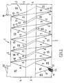
- la figure 1 est une représentation schématique d'une vue latérale d'un moteur diesel muni d'un pot d'échappement selon l'invention pour enlever les particules de suie des gaz d'échappement;
- la figure 2 représente une coupe longitudinale du pot d'échappement de la figure 1
- la figure 3 est une vue latérale de l'élément de purification du pot d'échappement de la figure 1
- la figure 4 est une coupe longitudinale de l'élément de purification représenté à la figure 3, à laquelle les particules de suie sont indiquées
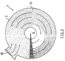
- la figure 5 est une coupe transversale de la première spire de l'élément de purification d'un pot d'échappement selon la figure 2 (vue de droite à gauche), à laquelle les particules de suie et le sens de passage des gaz d'échappement entrant sont indiqués.
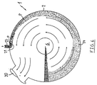
- la figure 6 est une coupe par la dernière spire de l'élément de purification d'un pot d'échappement selon la figure 2 (vue de droite à gauche), à laquelle les particules de suie et le sens de passage des gaz d'échappement purifiés et sortant sont indiqués.
- Figure 1 is a schematic representation of a side view of a diesel engine provided with an exhaust pipe according to the invention for removing soot particles from exhaust gases;
- Figure 2 shows a longitudinal section of the exhaust pipe of Figure 1
- Figure 3 is a side view of the purification element of the exhaust pipe of Figure 1
- Figure 4 is a longitudinal section of the purification element shown in Figure 3, to which the soot particles are indicated
- Figure 5 is a cross section of the first turn of the purification element of an exhaust pipe according to Figure 2 (view from right to left), to which the soot particles and the direction of gas passage d incoming exhaust are indicated.
- Figure 6 is a section through the last turn of the purification element of an exhaust pipe according to Figure 2 (view from right to left), to which the particles of soot and the direction of passage of the gases purified and outgoing exhaust are indicated.
Une forme de réalisation préférentielle (voir les figures 1, 2 et 3) d'un pot d'échappement (1) selon l'invention comprend un boîtier (2, 3, 4), comprenant un manteau cylindrique (2), une paroi plane avant (3) et arrière (4). Dans un espace clos à l'intérieur de ce boîtier (2, 3, 4) un élément de purification (5) est installé, comprenant un tuyau cylindrique central (6) qui s'étend sur toute la longueur du boîtier (2, 3, 4) dans le sens de l'axe longitudinal, et une paroi hélicoïdale avant (7) et arrière (8) délimitant latéralement un compartiment de passage hélicoïdal (9).A preferred embodiment (see Figures 1, 2 and 3) of an exhaust pipe (1) according to the invention comprises a housing (2, 3, 4), comprising a cylindrical mantle (2), a flat front wall (3) and rear wall (4). In a closed space inside this housing (2, 3, 4) a purification element (5) is installed, comprising a central cylindrical pipe (6) which extends over the entire length of the housing (2, 3 , 4) in the direction of the longitudinal axis, and a front (7) and rear (8) helical wall delimiting laterally a helical passage compartment (9).
Les bords intérieurs (10), (11) des parois hélicoïdales respectives (7), (8) se joignent au tuyau cylindrique (6) et s'étendent dans le sens d'une hélice respective (voir la figure 3), l'hélice de l'un des bords (11) étant décalée dans le sens de l'axe longitudinal (A) du tuyau central (6) par rapport à l'hélice de l'autre bord (10).The inner edges (10), (11) of the respective helical walls (7), (8) join the cylindrical pipe (6) and extend in the direction of a respective helix (see FIG. 3), the propeller of one of the edges (11) being offset in the direction of the longitudinal axis (A) of the central pipe (6) relative to the propeller of the other edge (10).
Les parois (7), (8) s'étendent depuis le tuyau central (6), se rapprochent l'une de l'autre et sont reliées l'une à l'autre par leurs bords extérieurs en formant un angle. Ces bords extérieurs (12) se joignent à l'intérieur du manteau cylindrique (2) et s'étendent suivant une hélice commune.The walls (7), (8) extend from the central pipe (6), approach each other and are connected to each other by their outer edges at an angle. These outer edges (12) join inside the cylindrical mantle (2) and extend along a common helix.
Les parois (7), (8) et le tuyau cylindrique (6) constituent un compartiment de passage hélicoïdal (9) d'une section transversale triangulaire.The walls (7), (8) and the cylindrical pipe (6) constitute a helical passage compartment (9) of a triangular cross section.
Ce compartiment de passage (9) est ouvert des deux extrémités, de manière que les gaz d'échappement puissent entrer dans l'élément de purification (5) par l'une des extrémités ouvertes - l'orifice d'admission (13) - et qu'ils puissent sortir de l'élément de purification (5) par l'autre extrémité ouverte - l'orifice d'écoulement.This passage compartment (9) is open at both ends, so that the exhaust gases can enter the purification element (5) through one of the open ends - the intake port (13) - and that they can exit from the purification element (5) through the other open end - the flow orifice.
Parce que les bords extérieurs (12) des parois hélicoïdales (7), (8) se joignent à la face intérieure du manteau cylindrique (2), des espaces clos sont formés dans le boîtier (2), (3), (4) entre les parties opposées de la face extérieure des parois (7), (8) (voir la figure 2). Ces espaces (15) sont enfermés à l'intérieur par les parties (16) du tuyau central (6) se trouvant à l'extérieur du compartiment de passage (9) et sont délimités latéralement par les parois (7), (8) de l'élément de purification (5) et limités à l'extérieur par le manteau (2).Because the outer edges (12) of the helical walls (7), (8) join the inner face of the cylindrical mantle (2), closed spaces are formed in the housing (2), (3), (4) between the opposite parts of the outer face of the walls (7), (8) (see Figure 2). These spaces (15) are enclosed inside by the parts (16) of the central pipe (6) located outside the passage compartment (9) and are delimited laterally by the walls (7), (8) of the purification element (5) and limited to the outside by the mantle (2).
La première spire de la paroi avant (7), la paroi plane avant (3) du boîtier, le tuyau (6) et le manteau (2) délimitent un compartiment d'admission (17). Dans la partie du manteau (2) qui délimite le compartiment d'admission (17) un orifice d'admission (18) a été prévu pour les gaz d'échappement à purifier.The first turn of the front wall (7), the flat front wall (3) of the housing, the pipe (6) and the mantle (2) define an intake compartment (17). In the part of the mantle (2) which delimits the intake compartment (17) an intake orifice (18) has been provided for the exhaust gases to be purified.
La dernière spire de la paroi arrière (8), la paroi plane arrière (4) du boîtier, le tuyau (6) et le manteau (2) délimitent un espace d'écoulement (19). Dans la partie du manteau (2) qui délimite l'espace d'écoulement (19), un orifice d'écoulement (20) pour les gaz d'échappement est prévu.The last turn of the rear wall (8), the rear flat wall (4) of the housing, the pipe (6) and the mantle (2) define a flow space (19). In the part of the mantle (2) which delimits the flow space (19), a flow orifice (20) for the exhaust gases is provided.
A proximité des bords extérieurs (12) des parois (7), (8), une paroi de séparation (21) est prévue dans la dernière spire du compartiment de passage (9), qui s'étend suivant le sens d'écoulement des gaz d'échappement et qui relie les deux parois (7), (8). La conduite triangulaire entre les parois (7), (8) et la paroi de séparation (21) a une extrémité ouverte qui se trouve dans le plan de l'orifice d'écoulement (14) qui est raccordé à une conduite d'évacuation (23), pour les particules de suie (24) se trouvant dans les gaz d'échappement, qui s'étend par un orifice (22) dans le manteau (2).Near the outer edges (12) of the walls (7), (8), a partition wall (21) is provided in the last turn of the passage compartment (9), which extends in the direction of flow of the exhaust gas and which connects the two walls (7), (8). The triangular pipe between the walls (7), (8) and the partition wall (21) has an open end which lies in the plane of the flow orifice (14) which is connected to a discharge pipe (23), for the soot particles (24) found in the exhaust gas, which extends through an orifice (22) in the mantle (2).
Les gaz d'échappement d'un moteur diesel (25) (voir la figure 1) sont introduits dans l'espace d'admission dans le boîtier par un tuyau d'amenée (26) raccordé à l'orifice d'admission (18) et entrent par l'orifice d'admission (13) dans le compartiment de passage hélicoïdal (9). Aux figures 1, 5 et 6, le sens d'écoulement des gaz d'échappement est indiqué par des flèches. Les gaz d'échappement passent par le compartiment de passage hélicoïdal (9), quittent le compartiment de passage (9) par l'orifice d'écoulement (14) et arrivent ainsi dans l'espace d'écoulement (19) et finalement passent vers l'extérieur par l'orifice d'évacuation (20) et par un tuyau d'évacuation (27), raccordé à cet orifice d'évacuation (20).The exhaust gases from a diesel engine (25) (see Figure 1) are introduced into the intake space in the housing through a supply pipe (26) connected to the intake port (18 ) and enter through the inlet (13) into the helical passage compartment (9). In Figures 1, 5 and 6, the direction of gas flow exhaust is indicated by arrows. The exhaust gases pass through the helical passage compartment (9), leave the passage compartment (9) through the flow orifice (14) and thus arrive in the flow space (19) and finally pass outwardly through the discharge port (20) and through a discharge pipe (27), connected to this discharge port (20).
Durant le trajet des gaz d'échappement à travers le compartiment de passage hélicoïdal (9) les particules de suie (24) se trouvant dans les gaz d'échappement sont chassées vers la partie extérieure du compartiment de passage (9), sous l'influence des forces centrifuges. Les particules de suie (24) sont emmenées par les gaz d'échappement. Dans la mesure où les gaz d'échappement pénètrent dans le compartiment de passage (9), de plus en plus de particules de suie (24) sont ramassée contre la partie extérieure des parois hélicoïdales (7), (8).During the path of the exhaust gases through the helical passage compartment (9) the soot particles (24) which are in the exhaust gases are expelled towards the external part of the passage compartment (9), under the influence of centrifugal forces. The soot particles (24) are carried away by the exhaust gases. As the exhaust gases enter the passage compartment (9), more and more soot particles (24) are collected against the external part of the helical walls (7), (8).
Ceci se voit clairement dans les figures 4, et 6. Finalement les particules de suie (24) sont ramassée, formant une couche compacte dans le caniveau en forme de V, constitué par les parties extérieures des parois (7), (8) et elles arrivent dans la conduite constituée par la paroi de séparation (21) et les parois (7), (8), pour finir dans la conduite d'évacuation (23) (voir les flèches P à la figure 6).This is clearly seen in Figures 4, and 6. Finally the soot particles (24) are collected, forming a compact layer in the V-shaped channel, formed by the outer parts of the walls (7), (8) and they arrive in the pipe formed by the partition wall (21) and the walls (7), (8), to finish in the discharge pipe (23) (see arrows P in Figure 6).
La conduite d'évacuation (23) débouche dans un filtre à suie (28), où les particules de suie (24) sont retenues. Une partie des gaz d'échappement passe par la conduite d'évacuation (23) vers le filtre à suie (28) et depuis ce filtre (28) elle peut s'échapper vers l'extérieur par un tuyau d'évacuation (29).The exhaust pipe (23) opens into a soot filter (28), where the soot particles (24) are retained. Part of the exhaust gas passes through the exhaust pipe (23) to the soot filter (28) and from this filter (28) it can escape to the outside through a discharge pipe (29) .
Le premier et le deuxième espace (15) - vus depuis la paroi avant (3) du boîtier - qui sont délimités par les faces extérieures opposées l'une à l'autre des parois hélicoïdales (7), (8), par le manteau (2) et par les parties du tuyau central se trouvant à l'extérieur du compartiment de passage (9) font fonction d'espace d'amortissement (15) pour amortir le bruit.The first and the second space (15) - seen from the front wall (3) of the housing - which are delimited by the external faces opposite to each other of the helical walls (7), (8), by the mantle (2) and by the parties central pipe located outside the passage compartment (9) function as a damping space (15) to dampen noise.
A cet effet, des orifices ont été prévus (ne pas représentés dans les figures) dans les parois (7), (8) délimitant ces espaces. Ces orifices permettent aux gaz d'échappement de passer d'une première partie du compartiment de passage (9) vers une deuxième partie du compartiment de passage (9) en passant par le premier espace d'amortissement (15) et de là de passer vers une troisième partie du compartiment de passage par le deuxième espace d'amortissement (15). A cet effet, les différentes parties du compartiment de passage (9) sont séparées l'une de l'autre par des parois non représentées sur les plans, alors que la première et la troisième partie sont en communication respectivement avec l'orifice d'admission (13) et l'orifice d'écoulement (14).For this purpose, orifices have been provided (not shown in the figures) in the walls (7), (8) delimiting these spaces. These orifices allow the exhaust gases to pass from a first part of the passage compartment (9) to a second part of the passage compartment (9) passing through the first damping space (15) and from there to pass towards a third part of the passage compartment through the second damping space (15). For this purpose, the different parts of the passage compartment (9) are separated from each other by walls not shown on the plans, while the first and the third part are in communication respectively with the orifice. inlet (13) and the flow orifice (14).
Donc, depuis l'orifice d'admission (13), les gaz d'échappement passent consécutivement par la première partie du compartiment de passage (9), par le premier espace d'amortissement (15), par la deuxième partie du compartiment de passage (9), par le deuxième espace d'amortissement (15) et par la troisième partie du compartiment de passage (9) vers l'orifice d'écoulement (14).Therefore, from the intake opening (13), the exhaust gases pass consecutively through the first part of the passage compartment (9), through the first damping space (15), through the second part of the passage (9), through the second damping space (15) and through the third part of the passage compartment (9) towards the flow orifice (14).
Les orifices par où les gaz d'échappement peuvent entrer dans le premier et le deuxième espace d'amortissement (15) ne se trouvent pas en face des orifices par où les gaz d'échappement peuvent entrer dans la deuxième partie, respectivement dans la troisième partie du compartiment de passage (9). Les orifices par où les gaz d'échappement peuvent entrer dans la deuxième partie du compartiment de passage (9) ne se trouvent pas en face des orifices par où les gaz d'échappement, depuis cette deuxième partie, peuvent entrer dans le deuxième compartiment d'insonorisation (15).The openings through which the exhaust gases can enter the first and the second damping space (15) are not opposite the openings through which the exhaust gases can enter the second part, respectively in the third part of the passage compartment (9). The orifices through which the exhaust gases can enter the second part of the passage compartment (9) are not opposite the orifices through which the exhaust gases, from this second part, can enter the second compartment d soundproofing (15).
Les orifices sont situés de telle manière que les gaz d'échappement doivent se déplacer dans les différentes parties du compartiment de passage (9) suivant le sens longitudinal du compartiment de passage hélicoïdal (9). Ce qui fait qu'une insonorisation optimale est atteinte.The holes are located in such a way that the exhaust gases must move through the different parts of the passage compartment (9) in the longitudinal direction of the helical passage compartment (9). This means that optimal soundproofing is achieved.
Avec ce pot d'échappement (1) on obtient des gaz d'échappement d'une grande pureté.With this exhaust pipe (1), exhaust gases of high purity are obtained.
La paroi de séparation (21) est réglable dans le sens radial. En installant la paroi de séparation (21) à une distance plus grande ou plus réduite des bords extérieurs (12) des parois (7), (8), une quantité de particules de suie (24) plus ou moins grande peut être enlevée des gaz d'échappement.The partition wall (21) is adjustable in the radial direction. By installing the partition wall (21) at a greater or lesser distance from the outer edges (12) of the walls (7), (8), a greater or lesser amount of soot particles (24) can be removed from the exhaust gas.
Le pot d'échappement (1), selon l'invention peut être exécuté de telle manière que les gaz d'échappement qui y passent subissent une contre-pression qui ne diffère que peu de la contre-pression que l'on obtient en utilisant les pots d'échappement connus. Ce pot d'échappement (1) n'a donc aucune influence défavorable sur le rendement du moteur (25).The exhaust pipe (1) according to the invention can be executed in such a way that the exhaust gases which pass therein undergo a back pressure which differs only slightly from the back pressure which is obtained by using known exhaust pipes. This exhaust (1) therefore has no adverse influence on the performance of the engine (25).
Un avantage supplémentaire du pot d'échappement (1) selon l'invention est que, au cas d'une obturation complète ou partielle de la conduite constituée entre la paroi de séparation (21) et la limitation extérieure (7), (8) ou de la conduite d'évacuation (23) y raccordée, le débit des gaz d'échappement par l'orifice d'écoulement (14) est encore suffisamment important, de sorte qu'aucune augmentation défavorable de ladite contre-pression ne se manifeste, et de sorte que le moteur peut continuer à tourner à un rendement presque inchangé.An additional advantage of the exhaust pipe (1) according to the invention is that, in the event of a complete or partial closure of the pipe formed between the partition wall (21) and the external limitation (7), (8) or of the discharge line (23) connected thereto, the flow of exhaust gases through the flow orifice (14) is still sufficiently large, so that no unfavorable increase in said back pressure occurs. , and so that the engine can continue to run at almost unchanged efficiency.
Claims (11)
Applications Claiming Priority (2)
| Application Number | Priority Date | Filing Date | Title |
|---|---|---|---|
| BE9600335A BE1010269A5 (en) | 1996-04-17 | 1996-04-17 | Device for purifying a fluid and muffler for engine fitted with such device. |
| BE9600335 | 1996-04-17 |
Publications (1)
| Publication Number | Publication Date |
|---|---|
| EP0802309A1 true EP0802309A1 (en) | 1997-10-22 |
Family
ID=3889681
Family Applications (1)
| Application Number | Title | Priority Date | Filing Date |
|---|---|---|---|
| EP97201114A Withdrawn EP0802309A1 (en) | 1996-04-17 | 1997-04-15 | Device for the purification of combustion engine exhaust gas |
Country Status (2)
| Country | Link |
|---|---|
| EP (1) | EP0802309A1 (en) |
| BE (1) | BE1010269A5 (en) |
Cited By (2)
| Publication number | Priority date | Publication date | Assignee | Title |
|---|---|---|---|---|
| CN100419227C (en) * | 2005-11-14 | 2008-09-17 | 中国科学院金属研究所 | Composite filtering-regeneration device for particulates in exhaust gas from diesel vehicle |
| BE1021830B1 (en) * | 2013-10-11 | 2016-01-21 | Darvan Invest N.V | DEVICE FOR SEPARATING SOLID PARTICLES FROM THE EXHAUST GASES OF AN ENGINE |
Citations (6)
| Publication number | Priority date | Publication date | Assignee | Title |
|---|---|---|---|---|
| BE636702A (en) * | ||||
| DE505889C (en) * | 1925-08-19 | 1930-08-26 | Pneumatic Conveyance & Extract | Device for removing dust and material particles from air, furnace duct gases and other gases, in which the gases are guided through curved ducts |
| FR1531161A (en) * | 1967-07-13 | 1968-06-28 | separator scrubber, centrifugal force, in particular for the elimination of radioactive products | |
| FR1572221A (en) * | 1968-01-26 | 1969-06-27 | ||
| US3495385A (en) * | 1967-08-21 | 1970-02-17 | Adolph C Glass | Air pollution control device |
| US3633343A (en) * | 1969-07-07 | 1972-01-11 | Walter J Mark | Automotive exhaust filter |
-
1996
- 1996-04-17 BE BE9600335A patent/BE1010269A5/en active
-
1997
- 1997-04-15 EP EP97201114A patent/EP0802309A1/en not_active Withdrawn
Patent Citations (6)
| Publication number | Priority date | Publication date | Assignee | Title |
|---|---|---|---|---|
| BE636702A (en) * | ||||
| DE505889C (en) * | 1925-08-19 | 1930-08-26 | Pneumatic Conveyance & Extract | Device for removing dust and material particles from air, furnace duct gases and other gases, in which the gases are guided through curved ducts |
| FR1531161A (en) * | 1967-07-13 | 1968-06-28 | separator scrubber, centrifugal force, in particular for the elimination of radioactive products | |
| US3495385A (en) * | 1967-08-21 | 1970-02-17 | Adolph C Glass | Air pollution control device |
| FR1572221A (en) * | 1968-01-26 | 1969-06-27 | ||
| US3633343A (en) * | 1969-07-07 | 1972-01-11 | Walter J Mark | Automotive exhaust filter |
Cited By (2)
| Publication number | Priority date | Publication date | Assignee | Title |
|---|---|---|---|---|
| CN100419227C (en) * | 2005-11-14 | 2008-09-17 | 中国科学院金属研究所 | Composite filtering-regeneration device for particulates in exhaust gas from diesel vehicle |
| BE1021830B1 (en) * | 2013-10-11 | 2016-01-21 | Darvan Invest N.V | DEVICE FOR SEPARATING SOLID PARTICLES FROM THE EXHAUST GASES OF AN ENGINE |
Also Published As
| Publication number | Publication date |
|---|---|
| BE1010269A5 (en) | 1998-04-07 |
Similar Documents
| Publication | Publication Date | Title |
|---|---|---|
| FR2533186A1 (en) | EMPTY SURCHARGER DEVICE DECOMPRESSOR FOR VEHICLES | |
| EP0057623B1 (en) | Exhaust gas silencer of a heat engine | |
| FR2933626A1 (en) | Gas separating device for case of internal combustion engine of road vehicle e.g. car, has liquid e.g. oil, draining channel arranged at side of treated gas downstream zone for flow of liquid passed through medium | |
| EP0584350B1 (en) | Two stroke internal combustion engine exhaust line | |
| FR2826058A1 (en) | SUCTION DEVICE FOR THE COMBUSTION AIR OF A THERMAL ENGINE OF A HAND-OPERATED TOOL | |
| FR2890696A1 (en) | TURBOMOTEUR WITH ATTENUATED JET NOISE | |
| FR3052522A1 (en) | DEVICE FOR RECOVERING LUBRICATING OIL EJECTED BY CENTRIFUGAL EFFECT IN A TURBOMACHINE | |
| FR2694051A1 (en) | Screw compressor provided with means for separating the oil from the oil-gas stream discharged by this compressor. | |
| WO2009147336A2 (en) | Oil separator for internal combustion engine | |
| FR2714699A1 (en) | Manually guided work device, including a motorized chain saw. | |
| FR2677264A1 (en) | ROTARY WASHING RAMP FILTER. | |
| FR2486596A1 (en) | DIRT SEPARATOR FOR TURBOMACHINES | |
| FR3062416A1 (en) | EXHAUST GAS TREATMENT DEVICE, EXHAUST LINE AND METHOD OF MANUFACTURING THE SAME | |
| EP0802309A1 (en) | Device for the purification of combustion engine exhaust gas | |
| EP0177996A2 (en) | Silencing apparatus for exhaust gases of internal-combustion engines | |
| FR2754470A1 (en) | OIL SEPARATOR DEVICE, PARTICULARLY FOR MOTOR VEHICLES | |
| FR2598176A1 (en) | SILENT FOR GAS CURRENT | |
| EP2324228B1 (en) | Filtration device for exhaust gases | |
| FR2536460A1 (en) | IMPROVED COMPACT DIFFUSER, PARTICULARLY SUITABLE FOR HIGH-GAS GAS TURBINES | |
| CA2982139A1 (en) | Turbine with internal blades | |
| EP1795733A1 (en) | Device for reducing the noise of an air circulation circuit, in particular for an internal combustion engine | |
| FR2477627A1 (en) | ABSORPTION EXHAUST POT | |
| FR2776706A1 (en) | Exhaust gas silencer for chain saw internal combustion engine | |
| FR2822499A1 (en) | CARBURETOR ARRANGEMENT | |
| FR2629518A1 (en) | Internal combustion engine and cylinder head for such an engine |
Legal Events
| Date | Code | Title | Description |
|---|---|---|---|
| PUAI | Public reference made under article 153(3) epc to a published international application that has entered the european phase |
Free format text: ORIGINAL CODE: 0009012 |
|
| AK | Designated contracting states |
Kind code of ref document: A1 Designated state(s): BE DE ES FR IT NL |
|
| 17P | Request for examination filed |
Effective date: 19980421 |
|
| 17Q | First examination report despatched |
Effective date: 20010208 |
|
| STAA | Information on the status of an ep patent application or granted ep patent |
Free format text: STATUS: THE APPLICATION IS DEEMED TO BE WITHDRAWN |
|
| 18D | Application deemed to be withdrawn |
Effective date: 20020503 |