EP0802074A1 - Method for detecting decrease of tyre air pressure and apparatus used therefor - Google Patents
Method for detecting decrease of tyre air pressure and apparatus used therefor Download PDFInfo
- Publication number
- EP0802074A1 EP0802074A1 EP97302472A EP97302472A EP0802074A1 EP 0802074 A1 EP0802074 A1 EP 0802074A1 EP 97302472 A EP97302472 A EP 97302472A EP 97302472 A EP97302472 A EP 97302472A EP 0802074 A1 EP0802074 A1 EP 0802074A1
- Authority
- EP
- European Patent Office
- Prior art keywords
- velocity
- judgement
- air pressure
- vehicle
- rotation
- Prior art date
- Legal status (The legal status is an assumption and is not a legal conclusion. Google has not performed a legal analysis and makes no representation as to the accuracy of the status listed.)
- Granted
Links
- 238000000034 method Methods 0.000 title claims abstract description 60
- 230000007423 decrease Effects 0.000 title claims abstract description 59
- 230000003247 decreasing effect Effects 0.000 claims abstract description 39
- 230000001133 acceleration Effects 0.000 description 28
- 238000001514 detection method Methods 0.000 description 12
- 239000006185 dispersion Substances 0.000 description 9
- 238000005096 rolling process Methods 0.000 description 7
- 230000000694 effects Effects 0.000 description 4
- 238000010586 diagram Methods 0.000 description 2
- 238000002360 preparation method Methods 0.000 description 2
- 238000005070 sampling Methods 0.000 description 2
- 230000009172 bursting Effects 0.000 description 1
- 230000005764 inhibitory process Effects 0.000 description 1
- 239000004973 liquid crystal related substance Substances 0.000 description 1
- 239000002861 polymer material Substances 0.000 description 1
- 230000001373 regressive effect Effects 0.000 description 1
Images


Classifications
-
- B—PERFORMING OPERATIONS; TRANSPORTING
- B60—VEHICLES IN GENERAL
- B60C—VEHICLE TYRES; TYRE INFLATION; TYRE CHANGING; CONNECTING VALVES TO INFLATABLE ELASTIC BODIES IN GENERAL; DEVICES OR ARRANGEMENTS RELATED TO TYRES
- B60C23/00—Devices for measuring, signalling, controlling, or distributing tyre pressure or temperature, specially adapted for mounting on vehicles; Arrangement of tyre inflating devices on vehicles, e.g. of pumps or of tanks; Tyre cooling arrangements
- B60C23/06—Signalling devices actuated by deformation of the tyre, e.g. tyre mounted deformation sensors or indirect determination of tyre deformation based on wheel speed, wheel-centre to ground distance or inclination of wheel axle
- B60C23/061—Signalling devices actuated by deformation of the tyre, e.g. tyre mounted deformation sensors or indirect determination of tyre deformation based on wheel speed, wheel-centre to ground distance or inclination of wheel axle by monitoring wheel speed
-
- B—PERFORMING OPERATIONS; TRANSPORTING
- B60—VEHICLES IN GENERAL
- B60Y—INDEXING SCHEME RELATING TO ASPECTS CROSS-CUTTING VEHICLE TECHNOLOGY
- B60Y2400/00—Special features of vehicle units
- B60Y2400/30—Sensors
- B60Y2400/303—Speed sensors
- B60Y2400/3032—Wheel speed sensors
Definitions
- the present invention relates to a method for detecting decrease of tyre air pressure and an apparatus used therefor. More particularly, the invention relates to a method for detecting decrease of tyre air pressure regardless of whether a vehicle is running at a low velocity or at a high velocity and an apparatus used therefor.
- the averaged data can be set to zero.
- an apparatus for detecting decrease of tyre air pressure in which each angular velocity of rotation of four tyres provided on a vehicle is detected, judgement is made as to whether the tyre air pressure is decreased or not based on the detected angular velocity of rotation, and when it is judged that the air pressure is lowered, alarm is issued,
- the apparatus comprising velocity detecting means for detecting the vehicle velocity, means for identifying whether the vehicle velocity detected by the velocity detecting means is higher than a predetermined threshold value or not, and drive condition detecting means for detecting whether the vehicle is in driven condition or not, wherein the judging means comprising judging means for low velocity which, when each angular velocity of rotation is detected by the velocity detecting means, judges as to whether the tyre air pressure is decreased or not based on the detected angular velocity of rotation; and judging means for high velocity which, when each angular velocity of rotation is detected, judges as to whether the tyre air pressure is decreased or not based on
- Step S7 judgement is made whether the air pressure is lowered or not by the following equation (5) (Step S7).
- Step S15 counting up is made to count the number of the data in the currently corresponding velocity region.
- the velocity V and the judgement value D' at every second which are usable for the velocity regression pressure decrease judgement processing for the vehicle which is running at a high velocity and in driven state, are added up to the divided region, and the number of the data in the region is counted.
- Step S 1 7 the judgement value D' obtained in the step S 1 6
- Step S 1 16 counting up is made to count the number of the data in the currently corresponding velocity region.
- the velocity V and the judgement value D' at every second which are usable for the velocity regression pressure decrease judgement processing for the vehicle running at a high velocity and in driven state, are added up to the divided region, and the number of the counters in the corresponding region is increased by one.
Abstract
Description
- The present invention relates to a method for detecting decrease of tyre air pressure and an apparatus used therefor. More particularly, the invention relates to a method for detecting decrease of tyre air pressure regardless of whether a vehicle is running at a low velocity or at a high velocity and an apparatus used therefor.
- In recent years, as one of the safety devices for the 4-wheel vehicles such as passenger cars and trucks, there have been proposed devices for detecting decrease of tyre air pressure, some of which have already been in practical application.
- The devices for detecting decrease of tyre air pressure are those developed under recognition of the important thereof mainly for the following reasons. Namely, when the air pressure decreases, the temperature of the tyre increases due to increase of deflection. When the temperature increases, the strength of polymer materials used for the tyre decreases, leading to bursting of the tyre. Normally, it frequently occurs for the driver not becoming aware of the loss of air in the tyre by about 0.5 atm. For this reason, an apparatus capable of detecting such loss of air pressure has been desired.
- The method of detecting decrease of air pressure in the above-mentioned tyre air pressure detecting device includes, for example, one based on the difference of the angular velocity of rotation F1, F2, F3 and F4 (hereinafter, when generally called, referred to angular velocity of rotation Fi) of four tyres W1, W2, W3 and W4 provided on the vehicle (tyres W1 and W2 correspond to the front left and right tyres, and tyres W3 and W4 correspond to the rear left and right tyres, respectively; hereinafter, when generally called, referred to tyre Wi).
- According to the method, for example, based on signals outputted from the wheel velocity sensor fitted to the tyre Wi, the angular velocity of rotation Fi of the tyre Wi is detected on each predetermined sampling period. Here, the detected angular velocity of rotation Fi is all the same, provided that the effective rolling radii of tyre Wi (amount obtained by dividing the distance of vehicle advance by 2π when the tyre rotated by one turn during free rotation of tyre) are all the same, and the vehicle runs linearly.
- On the other hand, the effective rolling radii of tyre Wi vary to meet, for example, the variation of air pressure of the tyre Wi. Namely, when the air pressure of the tyre Wi decreases, the effective rolling radius becomes smaller than in the case of normal inner pressure. Accordingly, the angular velocity of rotation Fi of the tyre Wi in which its air pressure is lowered become faster than in the case of normal inner pressure. Therefore, the decrease of air pressure of the tyre Wi can be detected by the difference of each angular velocity of rotation Fi.
- The judgement equation for detecting decrease of air pressure of the tyre Wi by the difference of angular velocity of rotation Fi is, for example, one as shown in the following equation (1) (refer to, for example, Japanese Unexamined Patent Publications No 305011/1988 and No 212609/1992)

- Assuming that the effective rolling radii of the above tyre Wi are all the same, the angular velocity of rotation Fi becomes all the same (F1 = F2 = F3 = F4), so that the judgement value D is 0. Therefore, when the threshold value DTH1 and DTH2 are set and the following equation (2) is satisfied, it is judged that there is a tyre Wi in which the air pressure is lowered, and when the equation (2) is not satisfied, it is judged that there is no tyre Wi whose air pressure is lowered. Further, when it is judged that there is a tyre Wi whose air pressure is lowered, an alarm is issued by, for example, a display device.

- However, with only the judgement of the air pressure decrease based on the above equations (1) and 2), there is a drawback of possibility of erroneous detection, depending on the vehicle running condition. For example, when the air pressure of any one tyre Wi of the tyres Wi shows decrease in air pressure, accurate detection can be made whether the air pressure is lowered or not if the vehicle is running at a relatively low velocity, while if the vehicle is running at a relatively high velocity with being driven, there is a possibility of erroneous detection to be made. The reason is because the slip rate of the depressurised wheel during the high velocity running is lowered, and the rolling radius increases by the centrifugal force of the tyre.
- In view of the above circumstances described above, an object of the present invention is to provide a method for detecting decrease of tyre air pressure and an apparatus used therefor capable of detecting accurately decrease of tyre air pressure regardless of the vehicle running condition, thereby preventing erroneous issuance or non-issuance of alarm (that is, notwithstanding the pressure decrease, no alarm is issued).
- A further object of the present invention is to provide a method for detecting decrease of tyre air pressure and an apparatus used therefor capable of detecting accurately decrease of tyre air pressure regardless of the vehicle running condition, especially regardless of the vehicle running velocity, thereby preventing erroneous issuance or non-issuance of alarm.
- In accordance with the present invention, there is provided a method for detecting decrease of tyre air pressure comprising detecting each angular velocity of rotation of four tyres provided on a vehicle, judging as to whether the tyre air pressure is decreased or not based on the detected angular velocity of rotation, and issuing alarm when it is judged that the air pressure is lowered, wherein the method includes a judgement step for low velocity in which, when the angular velocity of rotation is detected, judgement is made as to whether the tyre air pressure is decreased or not based on the detected angular velocity of rotation; and a judgement step for high velocity in which, when the angular velocity of rotation is detected, judgement is made as to whether the tyre air pressure is decreased or not based on the detected angular velocity of rotation only when the vehicle velocity is higher than a predetermined threshold value and the vehicle is in driven condition.
- Also, the judgement step for high velocity might be one wherein the vehicle velocities higher than a predetermined threshold value are divided into regions at certain intervals, and then, at the time when a predetermined number of data have been accumulated in a predetermined number of velocity ranges out of all the velocity ranges, the data coming within the velocity range satisfying the data number condition are averaged, followed by obtaining a secondary function by the least squares method from the averaged data to obtain the judgement value at medium and low velocities from the secondary function, so that the alarm can be detected based on the judgement value.
- Further, in the judgement step for high velocity, when the difference between the maximum value and the minimum value of the averaged data is less than the predetermined threshold value, the averaged data in all regions can be set to zero.
- With respect to the judgement step for high velocity, if there is an apprehension to cause erroneous judgement on operation in view of the region to be used for the least squares method or relation of the averaged data, then correction of data can be made.
- Also, in the judgement step for high velocity, if the high velocity region and the region to be used for the least squares method is near, the averaged data can be set to zero.
- Further, in the judgement step for high velocity, the threshold value of the alarm judgement might be changed depending on the region of the lower limit velocity of the averaged data to be used for the least squares method.
- Further, in the judgement step for high velocity, the averaged data of the lower limit velocity to be used for the least squares method might be weighted.
- Further, in accordance with the present invention, there is provided a method for detecting decrease of tyre air pressure comprising detecting each angular velocity of rotation of four tyres provided on a vehicle, judging as to whether the tyre air pressure is decreased or not based on the detected angular velocity of rotation, and issuing alarm when it is judged that the air pressure is lowered, wherein the method includes the steps of judging, during a low velocity, as to whether a judgement value obtained by correcting the detected angular velocity of rotation by information of the vehicle satisfies a predetermined threshold value or not; and during a high velocity and yet during driven condition, obtaining a judgement value in low velocity from relation between velocity from the optional velocity and the judgement value, thereby judging whether the judgement value satisfies a predetermined threshold value or not.
- In accordance with the present invention, there is further provided an apparatus for detecting decrease of tyre air pressure in which each angular velocity of rotation of four tyres provided on a vehicle is detected, judgement is made as to whether the tyre air pressure is decreased or not based on the detected angular velocity of rotation, and when it is judged that the air pressure is lowered, alarm is issued, the apparatus comprising velocity detecting means for detecting the vehicle velocity, means for identifying whether the vehicle velocity detected by the velocity detecting means is higher than a predetermined threshold value or not, and drive condition detecting means for detecting whether the vehicle is in driven condition or not, wherein the judging means comprising judging means for low velocity which, when each angular velocity of rotation is detected by the velocity detecting means, judges as to whether the tyre air pressure is decreased or not based on the detected angular velocity of rotation; and judging means for high velocity which, when each angular velocity of rotation is detected, judges as to whether the tyre air pressure is decreased or not based on the detected angular velocity of rotation only when the vehicle velocity detected by the velocity detecting means is judged to be higher than the predetermined threshold value in the identifying means and when the vehicle is judged to be in driven condition in the drive condition detecting means.
- Furthermore, there is provided an apparatus for detecting decrease of tyre air pressure in which each angular velocity of rotation of four tyres provided on a vehicle is detected, judgement is made as to whether the tyre air pressure is decreased or not based on the detected angular velocity of rotation, and when it is judged that the air pressure is lowered, alarm is issued, the apparatus comprising judging means for low velocity for judging, during a low velocity, as to whether a judgement value obtained by correcting the detected angular velocity of rotation by information of the vehicle satisfies a predetermined threshold value or not; and judging means for high velocity for judging, during a high velocity and yet during driven condition, obtaining a judgement value in low velocity from relation between the velocity from the optional velocity and the judgement value, thereby judging whether the judgement value satisfies a predetermined threshold value or not.
- Also, the judging means for high velocity might be one wherein the vehicle velocities higher than a predetermined threshold value are divided into regions at certain intervals, and then, at the time when a predetermined number of data have been accumulated in a predetermined number of velocity ranges out of all the velocity ranges, the data coming within the velocity range satisfying the data number condition are averaged, followed by obtaining a secondary function by the least square method from the average data to obtain the judgement value at medium and low velocities from the secondary function, so that the alarm can be detected based on the judgement value.
- Further, the judging means for high velocity, when the difference between the maximum value and the minimum value of the averaged data is less than the predetermined threshold value, can set the averaged data in all regions to zero.
- The judging means for high velocity, if there is an apprehension to cause erroneous judgement on operation in view of the region to be used for the least squares method or relation of the averaged data, can correct the data.
- Also, the judging means for high velocity, if the high velocity region and the region to be used for the least squares method are near, can set the averaged data to zero.
- Further, the judging means for high velocity can change the threshold value of the alarm judgement depending on the region of the lower limit velocity of the averaged data to be used for the least squares method.
- Further, the judging means for high velocity can weigh the averaged data of the lower limit velocity to be used for the least squares method.
- For the present invention, there are provided a plurality of judging means suited respectively to the vehicle running conditions. Accordingly, the judgement according to the vehicle running condition can be realised in any judging means.
- Accordingly, if it is judged that the tyre air pressure is decreased in at least one judging means of the plural judging means, it can be judged that the tyre air pressure is certainly lowered. In other words, in case that the tyres are all judged to be in normal inner pressures by all judging means, the tyres can be reliably judged to be in normal inner pressures.
- Further, in the present invention, with special notice of the point at what velocity the vehicle is running out of the vehicle running conditions, there are provided two judging means of one for low velocity and the other for high velocity.
- For example, when the air pressure of any tyre has decreased, on vehicle running at high velocity, there might occur cases where the difference in angular velocity of rotation becomes almost zero between the case where the air pressure is lowered and the case of normal inner pressure. For this reason, according to the judging means to carry out judgement on detection of the angular velocity of rotation, there is a likelihood for erroneous detection to occur. On the other hand, on examination by the inventor, it has been found that, even if a vehicle runs at a high velocity when the air pressure of any tyre is lowered, when the vehicle is in a driven state, according to the increase of velocity from a certain level, the difference in angular velocity of rotation between the case where the air pressure is lowered and the case of normal inner pressure decreases in a secondary function manner, and there has been found out a method of obtaining a difference in angular velocity of rotation between the case where the air pressure is lowered and the case of normal inner pressure at a low velocity from the secondary function.
- Accordingly, in the present invention, in addition to the judging means for low velocity to carry out judgement on detection of the angular velocity of rotation, there is provided judging means for high velocity to carry out judgement when there are satisfied conditions such that, after detection of the angular velocity of rotation, the vehicle velocity is more than the threshold value and yet the vehicle is in driven state. Therefore, regardless of the running velocity level of the vehicle, accurate detection can be made as to whether the air pressure of the tyre has decreased or not. Thus erroneous issuance or non-issuance of alarm can be prevented.
- Embodiments of the present invention will now be described in detail in conjunction with the accompanying drawings.
- Figure 1 is a block diagram to show an embodiment of an apparatus for detecting decrease of tyre air pressure according to the present invention;
- Figure 2 is a block diagram to show an electrical structure of the apparatus for detecting decrease of tyre air pressure in Figure 1;
- Figure 3 is a flow chart for illustrating alarm generation/stoppage process in the apparatus for detecting decrease of tyre air pressure in Figure 1;
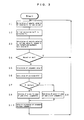
- Figures 4 and 5 are flow charts for illustrating the velocity regression pressure decreased judgement of the alarm generation/stoppage process in the apparatus for detecting decrease of tyre air pressure in Figure 1;
- Figure 6 is an illustrative view to show that, during a high velocity running of the vehicle, the front and rear accelerations are in positive range, and the judgement value decreases in secondary function manner according to increase of velocity;
- Figure 7 is a view illustrating the least squares method;
- Figure 8 is a flow chart for illustrating another embodiment of the apparatus for detecting decrease of tyre air pressure according to the present invention;
- Figure 9 and 10 are flow charts for illustrating the velocity regression pressure decrease judgement in Figure 8;
- Figure 11 is an illustrative view of erroneous judgement; and
- Figure 12 is a view for illustrating the least squares method relating to another embodiment.
- As shown in Figures 1 to 2, the apparatus for detecting decrease of tyre air pressure of the present invention detects whether the air pressures of the four tyres W1, W2, W3 and W4 provided on a four-wheel vehicle have decreased or not, and is furnished with ordinary
wheel velocity sensors 1 provided in connection with the tyres W1, W2, W3 and W4, respectively. The output of thewheel velocity sensor 1 is given to thecontrol unit 2. To thecontrol unit 2 there is connected adisplay 3 which is constituted by a liquid crystal display device, a plasma display device or CRT for notifying the tyre Wi whose air pressure has decreased. Also, since the tyre Wi is manufactured with dispersion within the standard, it is necessary to make correction so as to make the dynamic load radii of Wi identical within the normal inner pressure. For this purpose, thepart 4 is a switch to provide an initial step for the above correction. - The
control unit 2 includes, as shown in Figure 2, an I/O interface 2a which is necessary for receipt and delivery of signals with the external apparatuses,CPU 2 which functions as a nucleus of operation processing, ROM 2c storing control operation programs for theCPU 2b, andRAM 2d in which the data are temporarily written or from which the written data are read out for the purpose of the control operation of theCPU 2b. - In the above
vehicle velocity sensor 1, a pulse signal corresponding to the number of revolutions of the tire Wi (hereinafter referred to as a wheel velocity pulse, is outputted. InCPU 2b, based on the wheel velocity pulse outputted from thewheel velocity sensor 1, an angular velocity of rotation Fi of each tyre Wi is computed at each predetermined sampling period ▲T (sec), e.g., ▲T = 1 sec. - Next, explanation is given on the alarm generation/stoppage processing in the method of detecting decrease of tyre air pressure of the present invention. This process is realised by a software. First, as shown in Figure 3, based on the wheel velocity pulse outputted from the
wheel velocity sensor 1 for each one second, the angular velocity of rotation Fi of each tyre Wi is computed (Step S1). Here, since the tyre Wi is manufactured with including dispersion within the standard (initial difference), the effective rolling radius of each tyre Wi is not necessarily identical to one another even if all the tyres Wi fall within the normal inner pressure. For this reason, the angular velocity of rotation Fi of each tyre Wi is dispersed. Therefore, the corrected angular velocity of rotation Fli for cancelling the dispersion by initial difference is computed (Step S2). Concretely, the correction is made as in the equation shown below:


- The correction coefficients m and n are obtained by, for example, calculating the angular velocity of rotation Fi on the condition that the vehicle runs linearly, and calculating as m=F1/F2, n=F3/F4 based on the calculated angular velocity of rotation Fi.
- Then based on the above Fli, vehicle velocity V, turning radius R, lateral G, and forward and backward acceleration A are computed (Step S3).
- By the way, with respect to the above angular velocity of rotation Fi, depending on the size of the vehicle turning radius R, vehicle velocity V, vehicle lateral direction acceleration G, and forward and backward acceleration (hereinafter referred to simply as forward and backward acceleration) A, the dispersion become large, and as a result there is a likelihood to lead to misjudgement.
- That is to say, when the turning radius R is relatively small, there is a likelihood for the tyre Wi to slip sideways, so that there is a high possibility for the dispersion of the computed angular velocity of rotation Fi to become large. When the vehicle velocity V is extremely slow, the detection precision of the
vehicle velocity sensor 1 is remarkably lowered, so that there is a high possibility for the dispersion of the computed angular velocity of rotation Fi to become large. In the case where the lateral G of vehicle is relatively large, there is a possibility for the tyre Wi to slip sideways, so that there is a high possibility for the dispersion of the computed angular velocity of rotation Fi to become large. Further, in the case where the absolute value of the vehicle forward and backward acceleration A relatively large, there can be the effects of the slip of tyre Wi caused by the abrupt acceleration or abrupt deceleration of vehicle or of the foot brake, so that there is a high possibility for the dispersion of the computed angular velocities of rotation Fi to become large. As reviewed above, when there is a high possibility for the errors to be included in the angular velocity of rotation Fi, it is desirable for the angular velocity of rotation Fi not to be adopted for detecting air pressure decrease but to be rejected. - Accordingly, based on the size of the vehicle turning radius R, vehicle velocity V, vehicle lateral direction acceleration G, and forward and backward acceleration A, identification is made as to whether the angular velocity of rotation F1i obtained in the step S2 is rejected or not (Step S4).
- As a result of the identification in the Step S4, when the angular velocity of rotation F1i is not rejected, the judgement value D is computed by the equation (3) based on the angular velocity of rotation F1i (Step S5).

- By the way, the computation of the vehicle turning radius R, vehicle velocity V, vehicle lateral direction acceleration G, and forward and backward acceleration A in the above Step S5 is carried out by using the angular velocity of rotation F1i to which the correction of the initial difference is made. On the other hand, the effective rolling radius of the tyre Wi fluctuates by not only the initial difference but also the vehicle turning radius R, vehicle velocity V, vehicle lateral direction acceleration G, and forward and backward acceleration A. Accordingly, to the judgement value D obtained in the step S5, there are acted the effects of the fluctuation factors including the vehicle turning radius R, vehicle velocity V, vehicle lateral direction acceleration G, and forward and backward acceleration A.
- In view of the above, there is carried out a correction for rejecting the effects of the fluctuation factors of the judgement value D such as vehicle turning radius R, vehicle velocity V, vehicle lateral direction acceleration G, and forward and backward acceleration A (Step S6).
- Concretely, correction is made by the following equation (4).
- D'=D-α 1 x lateral G-α 2 x lateral G x A....(4) D' obtained in the Step S6 is temporarily stored in, for
example RAM 2d. - Here, in the above equation (4),
α 1 andα 2 are coefficients. These coefficients α 1 andα 2 are those previously obtainable by such procedures that the vehicle running test is carried out when it is known that each tyre Wi is normal, and based on the vehicle turning radius R, vehicle velocity V, vehicle lateral direction acceleration G, and forward and backward acceleration A calculated at that time. The coefficients α 1 andα 2 are previously memorised in, for example, the ROM 2c of thecontrol unit 2. - Using the judgement value D' after correction obtained in the step S6, judgement is made whether the air pressure is lowered or not by the following equation (5) (Step S7). In the equation (5), for example, DTH1 = DTH2 = 0.1.

- As a result, if the judgement value D' satisfies the equation (5), then it is judged that the air pressure has decreased, and if the same judgements are made for plural times continuously to some extent, then an alarm is issued (Step S9). On the contrary, if the judgement value D' does not satisfy the equation (5), then it is judged that the air pressure has not decreased, and if the same judgements are made for plural times continuously to some extent, then the alarm is deleted (Step S8). That is to say, because issuance or inhibition of alarm is not carried out every time when judgement is made whether the air pressures is lowered or the state is in normal inner pressure, but it is carried out when the same judgements are given continuously to some extent for plural periods, issuance/non-issuance of alarm under effect of abrupt factor such as noise can be prevented.
- By the way, in the case where the air pressure of any tyre Wi of the tyres Wi is decreased, if the vehicle is running at a relatively low velocity, the angular velocity of rotation Fi of the tyre Wi becomes faster than the angular velocity of rotation Fi of the normal inner pressure tyre Wi, so that the judgement value D' satisfies the equation (5) in the Step S7. On the contrary, in the case where the vehicle is running at a relatively high velocity, there are cases to show scarce difference between the angular velocity of rotation Fi of the tyre Wi whose air pressure has decreased and the angular velocity of rotation Fi of the tyre Wi whose inner pressure is normal. In such case, there is a high possibility for the judgement value D' to become zero, so that the air pressure of the tyre Wi is judged to be all normal in the
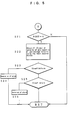
above Step 7. Accordingly, in the present embodiment, in consideration of the fact that, even when the vehicle is operated at a high velocity, if it is being driven, according to the increase in velocity from a certain level, the judgement value D' decreases in secondary function manner (refer to Figure 5), the judgement value D' at a low velocity by the secondary function is obtained. Then, even if the vehicle is running at a relatively high velocity, only in the case of the vehicle being driven, a preparation process for generation of alarm again (hereinafter referred to as velocity regression pressure decrease judgement method) is carried out (Step S10).
Next, the details of the above are explained with reference to the flow chart of Figure 4. - First, in order to carry out a velocity regression pressure decrease judgement method only in the case where the vehicle is running at a relatively high velocity and in driving condition, identification is made as to whether the vehicle velocity V is higher than the predetermined threshold value VTH (for example, VTH=120 km/h) or as to whether the forward and backward acceleration A for identifying whether the vehicle is in driven state or not is higher than the predetermined threshold value ATH (for example, ATH= 0 G) (Step S11).
- If, as a result, the vehicle velocity V is less than the predetermined threshold value VTH and the forward and backward acceleration A is less than the threshold value ATH, no inconvenience as described above should occur, so that it is unnecessary to carry out the velocity regression pressure decrease judgement method as described hereinafter. Also, in the case of judgement that the vehicle velocity V is less than the threshold value VTH or the forward and backward acceleration A is less than the threshold value ATH, no velocity regression pressure decrease judgement method is applied. In such cases, without undergoing the steps S12-S25, the sequence returns to the step S1. On the other hand, in case that the vehicle velocity V is judged to be higher than threshold value VTH and the forward and backward acceleration A to be higher than the threshold value ATH, the velocity regression pressure decrease judgement method in the steps S12-S26 as described is applied below.
- In the velocity regression pressure decrease judgement method, the process begins with the practice of classifying the velocity V at present by regions (Step S12). To explain the step S12 concretely, assuming for example to classify the velocity into the regions of 1 to 14 by 10 km/h from 120 km/h, if the velocity V at present is for example 135 km/h, since the velocity in the range of 120 km/h is in the region of 1, the data of 135 km/h comes under the 130 km/h range, so that it is included in the region of 2. The number of divisional regions is determined by the allowable velocity of vehicle.
- When the above processing is over, the current judgement value D' and velocity V are added to the velocity range allocated by the step S12 (Steps S13, S14). To explain concretely the steps S13 and S14, as will be understood from the flow chart of Figure 3, the velocity regression pressure decrease judgement processing is carried out at every second, and when the vehicle is judged to be running at a high velocity and in driven state from the velocity V and the forward and backward acceleration A at present, the steps S12 - S26 as shown in Figure 4 are to be practised. Accordingly, when the vehicle is judged to be running at a high velocity and in driven state, the processing is carried out such as to put the velocity V and the judgement value D' at every second into the corresponding region, and to add the value to the value added up so far.
- Next, counting up is made to count the number of the data in the currently corresponding velocity region (Step S15). To summarise the steps S11-S15 here, the velocity V and the judgement value D' at every second, which are usable for the velocity regression pressure decrease judgement processing for the vehicle which is running at a high velocity and in driven state, are added up to the divided region, and the number of the data in the region is counted.
- Next, examination is made as to whether there is any velocity region including not less that six data or not, with respect to all regions (Step 17). If there is, each average of the judgement value D' and the velocity V added so far in said region is obtained (Step S18) to count up how many regions containing not less than 6 data have been formed (Step S19). If there is no region, no special operation is made.
- If, on completion of these work steps, there are three velocity regions containing not less than 6 data, then there is obtained a judgement value D' at the time of the velocity = 0 km/h (CrosP) based on the averaged velocity V and the judgement value D' in the respective region, by the least squares method (Step S21 -S22).
- To explain concretely the least squares method, when a velocity V is taken on abscissa and a judgement value D' is taken on ordinate, the averaged velocity V and the judgement value D' corresponding thereto are to be plotted at three points (refer to Figure 6). Next, assuming a secondary curve y = a X2 + b passing through the centre of these three points, a method of obtaining a and b so that the total of the squares of the lengths of the lines taken from each point on the secondary curve so as to be parallel with the axis y becomes the minimum, is the least squares method used here. The value b herein corresponds to the above CrosP.
- If there is not three velocity regions having not less than 6 data, no special operation is made.
- Using the judgement value D' obtained in the step S22 (CrosP) by the equation (5), judgement is made as to whether the air pressure is decreased or not (Step S23 - S26). In the equation (6), for example, DHTH1 = DHTH2 = 0.1.

- As a result, if the judgement value CrosP satisfies the equation (6), then it is judged that the air pressure has decreased, and the alarm is issued (Step 24). On the other hand, if the judgement value CrosP does not satisfy the equation (6), then it is judged that the air pressure has not decreased, and alarm is cancelled (Step S26). When various conditions are met and a judgement of alarm is given, the variables in all velocity regions are cleared.
- Next, another embodiment of the present invention is described. As shown in Figure 8, the steps S11-
S 16 are the same as the steps S1-S6, in which, after termination of thestep S 15, the program advances to thestep S 16, and then, using the judgement value D' obtained in thestep S 16, various judgements on pressure decrease are made (Step S17). In the judgement on pressure decrease, judgement is made as to whether the air pressure has decreased or not by the equation (7), wherein, for example, DTH1 = DTH2 = 0.1.
- As a result, if the judgement value D' satisfies the equation (7), the alarm flag is set, while if not, the alarm flag is cleared.
- Next, the velocity regression pressure decrease judgement is carried out (Step S18),.which will be described in detail below. As a result, if the judgement value satisfies the alarm judgement conditions, an alarm flag is set, while if not, the alarm flag is cleared. Further, such processing is made that, if the alarm flag is set, then the alarm lamp is put on, and if not, the alarm lamp is put off (Steps S19-S111).
- By the way, in the same manner as in the foregoing embodiment, in the case where the air pressure of any tyre Wi of the tyres Wi is decreased, when the vehicle is running at a relatively low velocity, the angular velocity of rotation Fi of the tyre Wi becomes faster than the angular velocity of rotation Fi of the normal inner pressure tyre Wi, so that the judgement value D' satisfies the alarm judgement conditions in the
above Step S 17. Against this, in the case where the vehicle is running at a relatively high velocity, there are cases to show scarce difference between the angular velocity of rotation Fi of the tyre Wi whose air pressure has decreased and the angular velocity of rotation Fi of the tyre Wi whose inner pressure is normal. In such case, there is a high possibility for the judgement value D' to become zero, and the air pressure of the tyre Wi is judged to be all normal in theStep S 17. However, it is known that, even when the vehicle is operated at a high velocity, if it is being driven, according to the increase in velocity from a certain level, the judgement value D' decreases in secondary function manner (refer to Figure 6). - Accordingly, in the present embodiment, it is designed to obtain the judgement value D' at a low velocity by the secondary function, and even when the vehicle is running at a relatively high velocity, only in the case of the vehicle being driven, a preparation process for generation of alarm is carried out again.
- Next, the details of the above are explained with reference to the flow chart of Figures 9 and 10.
- First, in order to carry out a velocity regressive pressure decrease judgement method only in the case where the vehicle is running at a relatively high velocity and in driving condition, identification is made as to whether the vehicle velocity V is higher than the predetermined threshold value VTH (for example, VTH=85 km/h) or as to whether the forward and backward acceleration A for identifying whether the vehicle is in driven state or not is higher than the predetermined threshold value ATH for example, ATH=0G or -0.03G) (Step S113).
- If, as a result, it is judged that the vehicle velocity V is less than the predetermined threshold value VTH or the forward and backward acceleration A is less than the threshold value ATH, no phenomenon as described above should occur, so that the velocity regression pressure decrease judgement method as described hereinafter is not applied. In such case, without undergoing the steps S114-
S 125, the sequence returns to thestep S 19. On the other hand, in the case where the vehicle velocity V is judged to be higher than the threshold value VTH and the forward and backward acceleration A to be higher than the threshold value ATH, the velocity regression pressure decrease judgement method in the steps S114-S 125 as described later is applied. - In the velocity regression pressure decrease judgement method, the process begins with the practice of classifying the velocity V at present by regions (Step S114). To explain the step S114 concretely, assuming for example to classify the velocity into the regions of 1 to 14 by 5 km/h from 85 km/h to 155 km/h, if the velocity V at present is for example 100 km/h, since the velocity in the range of 85 km/h is in the region of 1, the data of 100 km/h comes under the 100 km/h range, so that it is to be included in the region of 4. The number of divisional regions is determined by the allowable velocity of vehicle.
- When the above processing is over, the current judgement value D' and velocity V are added to the velocity region allocated by the step S114 (Step S115). To explain concretely the
step S 115, as will be understood from the flow chart of Figure 8, the velocity regression pressure decrease judgement processing is carried out every second, and when the vehicle is judged to be running at a high velocity and in driven state from the velocity V and the forward and backward acceleration A at present, the steps S114-S 125 as shown in Figures 9 and 10 are to be practised. Accordingly, when the vehicle is judged to be running at a high velocity and in driven state, the processing is carried out such as to put the velocity V and the judgement value D' at every second into the corresponding region, and to add the value to the value added up so far. - Next, counting up is made to count the number of the data in the currently corresponding velocity region (Step S116). To summarise the steps S114-
S 116 here, the velocity V and the judgement value D' at every second, which are usable for the velocity regression pressure decrease judgement processing for the vehicle running at a high velocity and in driven state, are added up to the divided region, and the number of the counters in the corresponding region is increased by one. - Next, examination is made as to whether there are in all regions the predetermined number (e.g. four regions) of velocity regions having not less than the predetermined number (.e.g. 15) of data or not (Step S117). If there is, an average of the judgement value D' added so far in the region and mean value of each velocity region are obtained (Step S118).
- Further, when the difference between the maximum value and the minimum value of the average D' is less than the predetermined threshold value, i.e. 0.04, then the average D' in all regions is set to be zero (Step S119- S120). In this case, the alarm judgement value to be ultimately obtained should be made zero, so that no alarm is detected.
- In the present invention, the steps S119-
S 120 are not to be limited to them. For example, when operation is made from the region to be used for the least squares method or from the relation of the average D' in the steps S119-S 120, there is an apprehension to produce erroneous judgement. For example, with respect to the judgement value a obtained by regression, even if, as shown in Figure 11, the regression data are gathered in the four velocity ranges which are considerably separated from the medium and low velocities and the judgement value of the data show decrease against the increase in velocities, in the case where the difference c between the maximum value and the minimum value is of a dispersion degree within a normal inner pressure of, for example, not more than 0.03, there is a possibility for erroneous judgement to be led out if a regression curve is obtained on the basis of such value. The value d in Figure 11 is an alarm judgement threshold value. - Also, in the steps S119-
S 120, when the high velocity regions (e.g. higher than 150 km/h) and the regions to be used for the least squares method are near (e.g. the four regions are all adjacent), the average D' can be set to zero. - Alternatively, in the steps S119-
S 120, by the region of the lower limit velocity of the average D' (e.g. at the time of 150 km/h), the threshold value of the alarm judgement can be changed (e.g. to provide a variant for duplication). - Furthermore, in the steps S119-
S 120, by the region of the lower limit velocity of the average D' (e.g. at the time of 150 km/h), the average D' of the lower limit velocity might be weighted (e.g. to make two part equivalents). - If, on completion of these work steps, there are four regions containing not less than 15 data, then the judgement value D' at a low velocity (CrosP) is obtained by the least squares method, based on the intermediate velocity V averaged in the respective regions and the average D' (Step S121).
- To explain concretely the least square method, when a velocity V is taken on abscissa and an identification value D' is taken on ordinate, the intermediate velocity V in each region obtained from the above the judgement value D' corresponding thereto are to be plotted at four points (refer to Figure 12). Next, assuming a secondary curve y = a X2 + b passing through the centre of these four points, a method of obtaining a and b in such a manner that the total of the squares of the lengths of the lines taken from each point n the secondary curve so as to be parallel with the axis y becomes the minimum, is the least square method used here. The value b herein corresponds to the above CrosP.
- If there is not four velocity regions having not less than 15 data, no special operation is made.
- Using the judgement value D' (CrosP) obtained in the
step S 121, judgement is made as to whether the air pressure is decreased or not (Step S122-S125) by the equation (8). In the next equation (8), for example, DHTH1=DHTH2=0·1 .
- As a result, if the judgement value CrosP satisfies the equation (8), then it is judged that the air pressure has decreased, and an alarm flag is set (Step S123). On the other hand, if the judgement value CrosP does not satisfy the equation (8), then it is judged that the air pressure has not decreased, and the alarm flag is cleared (Step S124). When various conditions are met and a judgement if alarm is given, the variables in all velocity regions are cleared (Step S125).
- As described above, according to the present invention, there are provided a plurality of judging means suited respectively to the vehicle running conditions. Accordingly, the judgement according to the vehicle running condition can be realised in any judging means. Consequently, it is possible to detect accurately whether or not tyre air pressure decreases regardless of the vehicle running condition, and as a result it is possible to prevent erroneous issuance or non-issuance of alarm. Since this invention thus serves to improve the driver's reliability on the alarm, improvement of traffic safety can be expected.
- Furthermore, in addition to the judging means for low velocity to carry out judgement on detection of the angular velocity of rotation, there is provided judging means for high velocity such as to carry out judgement if the conditions such that, after the detection of the angular velocity of rotation, the vehicle velocity is not less than the threshold value and yet the vehicle is in driven state are satisfied. Therefore, regardless of the running velocity level of the vehicle, accurate detection can be made as to whether the air pressure of the tyre has decreased or not. Accordingly, erroneous issuance or non-issuance of alarm can be prevented. Consequently, since it is possible to improve the driver's reliability to the alarm, improvement of traffic safety can be expected.
Claims (6)
- A method for detecting decrease of tyre air pressure comprising detecting each angular velocity of rotation of four tyres provided on a vehicle, judging as to whether the tyre air pressure is decreased or not based on the detected angular velocity of rotation, and issuing alarm when it is judged that the air pressure is lowered, wherein the method includes a judgement step for low velocity in which, when the angular velocity of rotation is detected, judgement is made as to whether the tyre air pressure is decreased or not based on the detected angular velocity of rotation, and a judgement step for high velocity in which, when the angular velocity of rotation is detected, judgement is made as to whether the tyre air pressure is decreased or not based on the detected angular velocity of rotation only when the vehicle velocity is higher than a predetermined threshold value and the vehicle is in driven condition.
- A method for detecting decrease of tyre air pressure comprising detecting each angular velocity of rotation of four tyres provided on a vehicle, judging as to whether the tyre air pressure is decreased or not based on the detected angular velocity of rotation, and issuing alarm when it is judged that the air pressure is lowered, wherein the method includes the steps of judging, during a low velocity, as to whether a judgement value obtained by correcting the detected angular velocity of rotation by information of the vehicle satisfies a predetermined threshold value or not, and during a high velocity and yet during driven condition, obtaining a judgement value in medium and low velocity from relation between the velocity from the optional velocity and the judgement value, thereby judging whether the judgement value satisfies a predetermined threshold value or not.
- An apparatus for detecting decrease of tyre air pressure in which each angular velocity of rotation of four tyres provided on a vehicle is detected, judgement is made as to whether the tyre air pressure is decreased or not based on the detected angular velocity of rotation, and when it is judged that the air pressure is lowered, alarm is issued, the apparatus comprising velocity detecting means for detecting the vehicle velocity, means for identifying whether the vehicle velocity detected by the velocity detecting means is higher than a predetermined threshold value or not, and drive condition detecting means for detecting whether the vehicle is driving condition or not, wherein the judging means comprising judging means for low velocity which, when each angular velocity of rotation is detected by the velocity detecting means, judges as to whether the tyre air pressure is decreased or not based on the detected angular velocity of rotation, and judging means for high velocity which, when each angular velocity of rotation is detected, judges as to whether the tyre air pressure is decreased or not based on the detected angular velocity of rotation only when the vehicle velocity detected by the velocity detecting means is judged to be higher than the predetermined threshold value in the identifying means and when the vehicle is judged to be in driven condition in the drive condition detecting means.
- An apparatus for detecting decrease of tyre air pressure in which each angular velocity of rotation of four tyres provided on a vehicle is detected, judgement is made as to whether the tyre air pressure is decreased or not based on the detected angular velocity of rotation, and when it is judged that the air pressure is lowered, alarm is issued, the apparatus comprising judging means for low velocity for judging, during a low velocity, as to whether a judgement value obtained by correcting the detected angular velocity of rotation by information of the vehicle satisfies a predetermined threshold value or not; and judging means for high velocity for judging, during a high velocity and yet during driven condition, obtaining a judgement value in low velocity from relation between the velocity from the optional velocity and judgement value, thereby judging whether the judgement value satisfies a predetermined threshold value or not.
- A method according to either of claims 1 and 2, wherein the judgement step for high velocity is a step in which the vehicle velocities higher than a predetermined threshold value are divided into regions at certain intervals, and then, at the time when a predetermined number of data have been accumulated in a predetermined number of velocity ranges out of all the velocity ranges, the data number conditions are averaged, followed by obtaining a secondary function by the least squares method from the averaged data to obtain the judgement value at medium and low velocities from the secondary function, so that the alarm can be detected based on the judgement value.
- An apparatus according to either of claims 3 and 4, wherein the judging means for high velocity is means in which the vehicle velocities higher than a predetermined threshold value are divided into regions at certain intervals, and then, at the time when the data of the predetermined number of data have been accumulated in a predetermined number of velocity ranges out of all the velocity ranges, the data coming within the velocity range satisfying the data number conditions are averaged, followed by obtaining a secondary function by the least squares method from the averaged data to obtain the judgement value at medium and low velocities from the secondary function, so that the alarm can be detected based on the judgement value.
Applications Claiming Priority (3)
| Application Number | Priority Date | Filing Date | Title |
|---|---|---|---|
| JP9231196 | 1996-04-15 | ||
| JP9231196 | 1996-04-15 | ||
| JP92311/96 | 1996-04-15 |
Publications (2)
| Publication Number | Publication Date |
|---|---|
| EP0802074A1 true EP0802074A1 (en) | 1997-10-22 |
| EP0802074B1 EP0802074B1 (en) | 2003-08-20 |
Family
ID=14050864
Family Applications (1)
| Application Number | Title | Priority Date | Filing Date |
|---|---|---|---|
| EP97302472A Expired - Lifetime EP0802074B1 (en) | 1996-04-15 | 1997-04-11 | Method for detecting decrease of tyre air pressure and apparatus used therefor |
Country Status (4)
| Country | Link |
|---|---|
| US (1) | US5900543A (en) |
| EP (1) | EP0802074B1 (en) |
| KR (1) | KR100312875B1 (en) |
| DE (1) | DE69724176T2 (en) |
Cited By (5)
| Publication number | Priority date | Publication date | Assignee | Title |
|---|---|---|---|---|
| FR2785574A1 (en) | 1998-11-10 | 2000-05-12 | Jean Claude Galland | Detection of deflation of tyres while vehicle is in motion using difference in distance travelled by each wheel |
| WO2001044001A1 (en) * | 1999-12-15 | 2001-06-21 | Continental Aktiengesellschaft | Method and device for detecting a drop in pressure in motor vehicle tyres |
| US6285280B1 (en) | 2000-06-26 | 2001-09-04 | Robert Bosch Corporation | Method for detecting a deflated tire on a vehicle |
| US6459369B1 (en) | 2000-11-22 | 2002-10-01 | Robert Bosch Corporation | Tire deflation detection system with feedback component |
| DE10300330B4 (en) * | 2002-01-09 | 2018-12-06 | Continental Teves Ag & Co. Ohg | Method for detecting tire pressure loss |
Families Citing this family (12)
| Publication number | Priority date | Publication date | Assignee | Title |
|---|---|---|---|---|
| JP3340961B2 (en) * | 1997-10-06 | 2002-11-05 | 住友ゴム工業株式会社 | Tire pressure drop warning device and method |
| US6817236B1 (en) * | 1999-06-19 | 2004-11-16 | Continental Teves Ag & Co., Ohg | Method and device for creating a compensation value table for determining a test variable, and for identifying the pressure loss in a tire of a wheel |
| US8266465B2 (en) | 2000-07-26 | 2012-09-11 | Bridgestone Americas Tire Operation, LLC | System for conserving battery life in a battery operated device |
| US7161476B2 (en) | 2000-07-26 | 2007-01-09 | Bridgestone Firestone North American Tire, Llc | Electronic tire management system |
| JP3641419B2 (en) * | 2000-09-05 | 2005-04-20 | 住友ゴム工業株式会社 | Tire pressure drop alarm device and method |
| JP3869685B2 (en) * | 2001-06-20 | 2007-01-17 | 住友ゴム工業株式会社 | Two-wheeled vehicle air pressure drop detecting device and method, and two-wheeled vehicle decompression determination program |
| US20040178897A1 (en) * | 2001-07-09 | 2004-09-16 | Helmut Fennel | System and method for monitoring tire pressure in motor vehicles |
| DE10144362B4 (en) * | 2001-09-10 | 2005-10-27 | Siemens Ag | Method and system for detecting a change of state of a tire |
| JP2003267012A (en) * | 2002-01-09 | 2003-09-25 | Sumitomo Rubber Ind Ltd | Detecting method of decrease of tire air pressure, its device, and program of determining tire decompression |
| US20050109093A1 (en) * | 2003-11-21 | 2005-05-26 | Siemens Vdo Automotive Corporation | System and method for detecting low tire pressure |
| US6945103B1 (en) | 2004-04-26 | 2005-09-20 | Seetron Inc. | Tire status monitoring system |
| JP4637011B2 (en) * | 2005-12-12 | 2011-02-23 | 住友ゴム工業株式会社 | Tire pressure abnormality alarm method, apparatus and program |
Citations (2)
| Publication number | Priority date | Publication date | Assignee | Title |
|---|---|---|---|---|
| EP0652121A1 (en) * | 1993-11-04 | 1995-05-10 | Sumitomo Electric Industries, Limited | Tire air-pressure reduction detecting method and apparatus |
| EP0656268A1 (en) * | 1992-09-16 | 1995-06-07 | Sumitomo Electric Industries, Ltd. | Apparatus for and method of detecting decrease of air pressure in tire |
Family Cites Families (7)
| Publication number | Priority date | Publication date | Assignee | Title |
|---|---|---|---|---|
| GB8711310D0 (en) * | 1987-05-13 | 1987-06-17 | Sp Tyres Uk Ltd | Tyres deflation warning device |
| GB9002925D0 (en) * | 1990-02-09 | 1990-04-04 | Sumitomo Rubber Ind | Method of detecting a deflated tyre on a vehicle |
| GB9026560D0 (en) * | 1990-12-06 | 1991-01-23 | Sumitomo Rubber Ind | Method of detecting a deflated tyre on a vehicle |
| JP2780887B2 (en) * | 1992-01-31 | 1998-07-30 | 本田技研工業株式会社 | Vehicle tire pressure determination device |
| EP0607690B1 (en) * | 1992-12-21 | 1997-02-19 | Sumitomo Rubber Industries Limited | Method and device for detecting pneumatic abnormalities of tyre |
| JPH08164720A (en) * | 1994-12-15 | 1996-06-25 | Sumitomo Electric Ind Ltd | Tire air pressure reduction detecting method and tire air pressure reduction detecting device |
| JP3119809B2 (en) * | 1996-01-26 | 2000-12-25 | 住友電気工業株式会社 | Method and apparatus for detecting decrease in tire air pressure |
-
1997
- 1997-04-10 KR KR1019970013296A patent/KR100312875B1/en not_active IP Right Cessation
- 1997-04-10 US US08/838,736 patent/US5900543A/en not_active Expired - Lifetime
- 1997-04-11 DE DE69724176T patent/DE69724176T2/en not_active Expired - Lifetime
- 1997-04-11 EP EP97302472A patent/EP0802074B1/en not_active Expired - Lifetime
Patent Citations (2)
| Publication number | Priority date | Publication date | Assignee | Title |
|---|---|---|---|---|
| EP0656268A1 (en) * | 1992-09-16 | 1995-06-07 | Sumitomo Electric Industries, Ltd. | Apparatus for and method of detecting decrease of air pressure in tire |
| EP0652121A1 (en) * | 1993-11-04 | 1995-05-10 | Sumitomo Electric Industries, Limited | Tire air-pressure reduction detecting method and apparatus |
Cited By (5)
| Publication number | Priority date | Publication date | Assignee | Title |
|---|---|---|---|---|
| FR2785574A1 (en) | 1998-11-10 | 2000-05-12 | Jean Claude Galland | Detection of deflation of tyres while vehicle is in motion using difference in distance travelled by each wheel |
| WO2001044001A1 (en) * | 1999-12-15 | 2001-06-21 | Continental Aktiengesellschaft | Method and device for detecting a drop in pressure in motor vehicle tyres |
| US6285280B1 (en) | 2000-06-26 | 2001-09-04 | Robert Bosch Corporation | Method for detecting a deflated tire on a vehicle |
| US6459369B1 (en) | 2000-11-22 | 2002-10-01 | Robert Bosch Corporation | Tire deflation detection system with feedback component |
| DE10300330B4 (en) * | 2002-01-09 | 2018-12-06 | Continental Teves Ag & Co. Ohg | Method for detecting tire pressure loss |
Also Published As
| Publication number | Publication date |
|---|---|
| EP0802074B1 (en) | 2003-08-20 |
| DE69724176D1 (en) | 2003-09-25 |
| US5900543A (en) | 1999-05-04 |
| KR100312875B1 (en) | 2001-12-12 |
| DE69724176T2 (en) | 2004-02-26 |
| KR19980076549A (en) | 1998-11-16 |
Similar Documents
| Publication | Publication Date | Title |
|---|---|---|
| EP0802074A1 (en) | Method for detecting decrease of tyre air pressure and apparatus used therefor | |
| US5828975A (en) | Method and device for calculating turning radius of vehicle taking load movement thereof into consideration | |
| US5959202A (en) | Device for determining initial correction factor for correcting rotational velocity of tire | |
| EP0832766B1 (en) | Tire pressure detecting device | |
| US5629478A (en) | Method of and device for detecting tire pressure drop based on angular velocity | |
| US5710539A (en) | Tire air-pressure reduction detecting apparatus | |
| EP1752317B1 (en) | Method for detecting decrease in inner pressure of tire using GPS speed information | |
| US5524482A (en) | Detecting a deflated vehicle tire by comparing angular velocity data of all wheels, a data table, and the directly-measured pressure of a single tire | |
| EP0724974B1 (en) | Tire pressure drop alarm device | |
| JP4823642B2 (en) | Tire pressure drop warning method and apparatus using GPS information, and tire pressure drop warning program | |
| US5442331A (en) | Method and device for detecting a deflated tire by comparing angular velocity and forward/backward speed data with a data table | |
| GB2326007A (en) | Vehicle tyre pressure monitoring system | |
| EP1674303B1 (en) | Means for detecting loss of pneumatic pressure in tire and device for the purpose | |
| US5907097A (en) | Method of and device for detecting tire pressure drop | |
| EP2110269A1 (en) | Method and apparatus for detecting decrease in tire air pressure and program for determing decrease in tire air pressure | |
| US6055488A (en) | Device for calculating initial correction factor for correcting rotational velocity of tire | |
| US5940781A (en) | Tire pressure drop detecting device | |
| EP1190874A2 (en) | Apparatus and method for alarming decrease in tyre air pressure | |
| US6691059B1 (en) | Method and device for the detection of a pressure drop in a tire of a vehicle wheel | |
| JP3129671B2 (en) | Method and apparatus for detecting decrease in tire air pressure | |
| JP3167278B2 (en) | Method and apparatus for detecting decrease in tire air pressure | |
| JP3623023B2 (en) | Tire pressure drop detection method and apparatus | |
| WO2023214003A1 (en) | Methods, apparatuses and computer program products for determining the severity of a deflation of a tire | |
| JP3396522B2 (en) | Tire pressure drop determination method and tire pressure drop detection device |
Legal Events
| Date | Code | Title | Description |
|---|---|---|---|
| PUAI | Public reference made under article 153(3) epc to a published international application that has entered the european phase |
Free format text: ORIGINAL CODE: 0009012 |
|
| AK | Designated contracting states |
Kind code of ref document: A1 Designated state(s): DE FR GB IT SE |
|
| 17P | Request for examination filed |
Effective date: 19971106 |
|
| 17Q | First examination report despatched |
Effective date: 20000222 |
|
| GRAH | Despatch of communication of intention to grant a patent |
Free format text: ORIGINAL CODE: EPIDOS IGRA |
|
| GRAS | Grant fee paid |
Free format text: ORIGINAL CODE: EPIDOSNIGR3 |
|
| GRAA | (expected) grant |
Free format text: ORIGINAL CODE: 0009210 |
|
| AK | Designated contracting states |
Designated state(s): DE FR GB IT SE |
|
| REG | Reference to a national code |
Ref country code: GB Ref legal event code: FG4D |
|
| REF | Corresponds to: |
Ref document number: 69724176 Country of ref document: DE Date of ref document: 20030925 Kind code of ref document: P |
|
| REG | Reference to a national code |
Ref country code: SE Ref legal event code: TRGR |
|
| ET | Fr: translation filed | ||
| PLBE | No opposition filed within time limit |
Free format text: ORIGINAL CODE: 0009261 |
|
| STAA | Information on the status of an ep patent application or granted ep patent |
Free format text: STATUS: NO OPPOSITION FILED WITHIN TIME LIMIT |
|
| 26N | No opposition filed |
Effective date: 20040524 |
|
| REG | Reference to a national code |
Ref country code: FR Ref legal event code: PLFP Year of fee payment: 20 |
|
| PGFP | Annual fee paid to national office [announced via postgrant information from national office to epo] |
Ref country code: FR Payment date: 20160309 Year of fee payment: 20 |
|
| PGFP | Annual fee paid to national office [announced via postgrant information from national office to epo] |
Ref country code: GB Payment date: 20160406 Year of fee payment: 20 Ref country code: DE Payment date: 20160405 Year of fee payment: 20 |
|
| PGFP | Annual fee paid to national office [announced via postgrant information from national office to epo] |
Ref country code: SE Payment date: 20160412 Year of fee payment: 20 Ref country code: IT Payment date: 20160418 Year of fee payment: 20 |
|
| REG | Reference to a national code |
Ref country code: DE Ref legal event code: R071 Ref document number: 69724176 Country of ref document: DE |
|
| REG | Reference to a national code |
Ref country code: GB Ref legal event code: PE20 Expiry date: 20170410 |
|
| PG25 | Lapsed in a contracting state [announced via postgrant information from national office to epo] |
Ref country code: GB Free format text: LAPSE BECAUSE OF EXPIRATION OF PROTECTION Effective date: 20170410 |