EP0802058A2 - Method of filling ink in ink supply passages - Google Patents
Method of filling ink in ink supply passages Download PDFInfo
- Publication number
- EP0802058A2 EP0802058A2 EP97111200A EP97111200A EP0802058A2 EP 0802058 A2 EP0802058 A2 EP 0802058A2 EP 97111200 A EP97111200 A EP 97111200A EP 97111200 A EP97111200 A EP 97111200A EP 0802058 A2 EP0802058 A2 EP 0802058A2
- Authority
- EP
- European Patent Office
- Prior art keywords
- ink
- print head
- head unit
- suction
- suction pump
- Prior art date
- Legal status (The legal status is an assumption and is not a legal conclusion. Google has not performed a legal analysis and makes no representation as to the accuracy of the status listed.)
- Granted
Links
Images


Classifications
-
- B—PERFORMING OPERATIONS; TRANSPORTING
- B41—PRINTING; LINING MACHINES; TYPEWRITERS; STAMPS
- B41J—TYPEWRITERS; SELECTIVE PRINTING MECHANISMS, i.e. MECHANISMS PRINTING OTHERWISE THAN FROM A FORME; CORRECTION OF TYPOGRAPHICAL ERRORS
- B41J2/00—Typewriters or selective printing mechanisms characterised by the printing or marking process for which they are designed
- B41J2/005—Typewriters or selective printing mechanisms characterised by the printing or marking process for which they are designed characterised by bringing liquid or particles selectively into contact with a printing material
- B41J2/01—Ink jet
- B41J2/17—Ink jet characterised by ink handling
- B41J2/175—Ink supply systems ; Circuit parts therefor
- B41J2/17503—Ink cartridges
- B41J2/1752—Mounting within the printer
-
- B—PERFORMING OPERATIONS; TRANSPORTING
- B41—PRINTING; LINING MACHINES; TYPEWRITERS; STAMPS
- B41J—TYPEWRITERS; SELECTIVE PRINTING MECHANISMS, i.e. MECHANISMS PRINTING OTHERWISE THAN FROM A FORME; CORRECTION OF TYPOGRAPHICAL ERRORS
- B41J2/00—Typewriters or selective printing mechanisms characterised by the printing or marking process for which they are designed
- B41J2/005—Typewriters or selective printing mechanisms characterised by the printing or marking process for which they are designed characterised by bringing liquid or particles selectively into contact with a printing material
- B41J2/01—Ink jet
- B41J2/17—Ink jet characterised by ink handling
- B41J2/175—Ink supply systems ; Circuit parts therefor
- B41J2/17503—Ink cartridges
- B41J2/17506—Refilling of the cartridge
-
- B—PERFORMING OPERATIONS; TRANSPORTING
- B41—PRINTING; LINING MACHINES; TYPEWRITERS; STAMPS
- B41J—TYPEWRITERS; SELECTIVE PRINTING MECHANISMS, i.e. MECHANISMS PRINTING OTHERWISE THAN FROM A FORME; CORRECTION OF TYPOGRAPHICAL ERRORS
- B41J2/00—Typewriters or selective printing mechanisms characterised by the printing or marking process for which they are designed
- B41J2/005—Typewriters or selective printing mechanisms characterised by the printing or marking process for which they are designed characterised by bringing liquid or particles selectively into contact with a printing material
- B41J2/01—Ink jet
- B41J2/17—Ink jet characterised by ink handling
- B41J2/175—Ink supply systems ; Circuit parts therefor
- B41J2/17503—Ink cartridges
- B41J2/17513—Inner structure
-
- B—PERFORMING OPERATIONS; TRANSPORTING
- B41—PRINTING; LINING MACHINES; TYPEWRITERS; STAMPS
- B41J—TYPEWRITERS; SELECTIVE PRINTING MECHANISMS, i.e. MECHANISMS PRINTING OTHERWISE THAN FROM A FORME; CORRECTION OF TYPOGRAPHICAL ERRORS
- B41J2/00—Typewriters or selective printing mechanisms characterised by the printing or marking process for which they are designed
- B41J2/005—Typewriters or selective printing mechanisms characterised by the printing or marking process for which they are designed characterised by bringing liquid or particles selectively into contact with a printing material
- B41J2/01—Ink jet
- B41J2/17—Ink jet characterised by ink handling
- B41J2/175—Ink supply systems ; Circuit parts therefor
- B41J2/17563—Ink filters
Definitions
- the present invention relates generally to a method of filling ink in ink supply passages.
- An ink-jet type recording apparatus includes a couple of types, i.e., one type where an ink tank is disposed on a suitable portion of a body and ink is supplied from the ink tank to a print head unit through an ink supply pipe such as a tube, and another type where an ink tank is housed on a carriage on which a print head unit is mounted.
- the latter type so called an on-carriage type, has an advantage in that the ink supply pipe is not required.
- the ink tank, an ink supply passage, a filter and the like must be disposed in a limited space, i.e., on a carriage. That is, freedom in structural design is suppressed. Therefore, particularly it would be technically difficult to avoid air bubbles which likely generate when ink is supplied from the ink tank to the print head unit or eliminate the air bubbles once occurred. Further, when the ink tank is mounted on the carriage manually, unintentional accidents like a mechanical damage to the peripheral devices may occur or air bubble may enter the ink tank.
- filling fluid is required to be filled in the ink supply passages of the print head unit at the time of the off-the-shelf to avoid problems caused by air bubbles which may arise when ink is initially filled in the passages.
- the present invention provides an improved method of filling ink in ink supply passages according to independent claims 1 and 3.
- An ink-jet type recording apparatus preferably one in which a print head and an ink-tank are mounted on a carriage, is capable of exhausting air bubbles immediately after they are generated, reducing a possibility of unintentional accidents, and supplying ink even in case where a positional deflection presents between the ink tank and the print head unit.
- the ink-jet type recording apparatus is capable of controlling generations of air bubbles in an ink supply passage from the ink tank to the print head.
- An ink-jet type recording apparatus includes a connecting member which is provided with a first ink supply passage disposed in a carriage and extending in parallel toward a print head unit and a second ink supply passage extending upwardly and communicated with the ink tank and the first ink supply passage, an ink head unit connected to the connecting member for jetting ink droplets corresponding to print signals, a hollow needle engaging with a needle insertion hole of the ink tank, a filter member provided in parallel with a tapered concave portion formed between the hollow needle and the second ink supply passage, a cap member detachably mounted on the print head unit for communicating with a suction pump, and a control member for driving the suction pump in a first suction mode which operates intervally and a second suction mode which operates continuously.
- the filter member After mounting the ink tank onto the carriage, when ink is supplied to the print head unit, the ink flows through the filter member smoothly under the first suction mode thereby to suppress the occurrence of air bubbles by the filter member. Since the filter member is disposed between an upper and lower tapered concave members the air bubbles generated in this area moves along inclined surface of the concave member toward the ink tank so that the air bubbles do not flow into the print head unit.
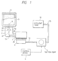
- Fig. 1 is a schematic view showing a print head unit 1 of an ink-jet type connected to an ink tank 3 through a connecting member 2.
- Ink which is impregnated in a foam member 11 accommodated within the ink tank 3 is supplied to the print head unit through a hollow needle 9 and an ink supply passage 13 defined in the connecting member 2, so that the print head unit 1 emits ink droplets in accordance with print signals.
- Fig. 2 is a perspective view showing one example of the print head unit 1 illustrated in Fig. 1.
- the ink is flown to a reservoir 20 through a rising conduit 15 coupled to the ink supply passage 13, and the reservoir 20 supplies through an ink supply port 21 ink therein by an amount consumed by each of a pressure generating chamber 22.
- a vibrating plate 23 seals the pressure generating chambers 22, and an end of each piezoelectric vibrating members 24, 24, 24... abuts against the vibrating plate 23 at a position corresponding to the respective pressure generating chambers 22, 22, 22...
- the apparatus also includes a cap member 4 disposed at non-printing area, which cap member comes into abutment against the nozzle plate 26 of the print head unit 1 by a drive mechanism (not shown) for preventing the nozzle openings 27, 27, 27... from drying.
- the cap member 4 connects through a tube 12 to a suction pump 5 which is operated by a control device 6 to suck corrected ink in the cap member 4.
- the suction pump 5 may be of a so-called tube pump type in which a plurality of rollers arranged on a support member spaced apart from one another on a common periphery thereof abut elastically against an elastic tube arranged circularly, and the support member is rotated in one direction by a direct current motor.
- the apparatus shown in Fig. 1 is also provided with an effluent tank 10 connected to an outlet port of the suction pump 5 through a tube 113.
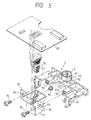
- Fig. 3 is a perspective view showing one embodiment of the carriage on which the print head unit and the ink tank are mounted.
- a carriage 30 reciprocally moves along a platen (not shown) guided by a guide lock 31.
- An ink tank holder 32 is disposed on an upper surface of the carriage 30 for holding the ink tank 3.
- a lever 33 is rotatably supported on the holder 32 for holding and securing the ink tank 3 by engaging with an engagement section of the ink tank 3.
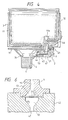
- Fig. 4 is a sectional view showing a state where the print head unit 1, the carriage 30 and the connecting member 2 connected therebetween.
- the connecting member 2, especially an elastic joint 95 thereof is disposed between the ink tank 3 and the print head unit 1 for preventing a downward force of the ink tank 3 from largely transferring to the print head unit 1 when the ink tank 3 is mounted on the carriage 30, and absorbing the positional deflection created therebetween. Therefore, the ink tank 3 and the print head unit 1 are affirmly engaged therewith.
- the ink supply port 46 has a wall 46a projecting inward of the housing of the ink tank 3 and compressing the foam member 11 in the vicinity of the ink supply port 46. Since the pore size of the foam member 11 which is compressed by the wall 46a of the ink supply port 46 is smaller than that of the other part, the capillary force of the foam member 11 in the vicinity of the ink supply port 46 is large compared to the other portion thereof. Accordingly, ink which is impregnated in the foam member 11 is gathered toward the ink supply port 46 so that ink can be consumed up to the last drop.
- the wall 46a of the ink supply port 46 is located close to and spaced from the wall of the ink tank housing as shown in Fig. 4.
- the connecting member 2 is generally U-shaped and provided with a body 42 and a pair of leg portions 41, 41 disposed at both sides of the body 42.
- a cylinder body 44 for receiving a connecting conduit 43 of the ink tank 3 is formed on an upper center of the body 42 between the leg portions 41 and 41.
- a first ink supply path 45 directing substantially in parallel with respect to the recording apparatus connects an inner side surface 42a of the body 42 to the center of the cylinder body 44.
- a hollow needle 9 projects upward from a center part of the cylinder body 44 and communicates with the ink supply path 45, The hollow needle 9 penetrates the ink supply port 46 of the ink tank 3.
- a through hole 50 of the needle 9 communicates with the first ink path 45 through a second ink supply path 47 directing substantially in vertical with respect to the recording apparatus.
- a filter member 51 is arranged in a flow passage connecting between the hollow needle 9 and the second ink supply path 47. Specifically, the filter member 51 positions between a tapered concave portion 52, an upper portion of which is widened, formed in the connecting member body and a tapered concave portion 53, a lower portion of which is widened, formed below the hollow needle 9.
- the filter member 51 is laid in and perpendicular to a vertical ink supply passage communicating between the through hole 50 of the hollow needle 9 and the second ink supply path 47.
- the filter member 51 is formed of SUS fine wires by twill weaving to approximately 2000 mesh.
- the taper angles ⁇ 1 and ⁇ 2 of the concave portion 52 and 53, respectively, are defined within a range between substantially 30° and 60°. These angles are selected to have a function to efficiently lead air bubbles within the concave portions 52 and 53 to move upward therealong.
- Figs. 7A, 7B and 7C show a process of assembling the filter member 51.
- a concave 80 formed at an opening part of the tapered concave portion 52 formed on the connecting member body 42a is designed to have a diameter engageable with a bottom of the hollow needle 9.
- the tapered concave portion 52 is formed at the center of the concave 80.
- a ring-like protrusion 82 is formed on a step part 81 to surround the tapered concave portion 52.
- the filter member 51 is laid on the ring-like protrusion 82 as shown in Fig. 7A. Under this condition, a heat is applied to the protrusion 82 through the filter member 51 so that a fusing part 82' of the protrusion 82 is selectively fused to penetrate into the mesh of the filter member 51 as illustrated in Fig. 7B.
- the hollow needle 9 is provided with a flange 86 contacting an upper surface 87 of the connecting member body 42 in the vicinity of a bottom 85 thereof which is engageable with the concave 80 of the connecting member body 42.
- the flange 86 is provided with an annular groove 88 on the bottom surface thereof and an annuler protrusion 89 which is V-shaped in cross section.
- the annular protrusion 89 is disposed at an outer side of the annular groove 88.
- the hollow needle 9 is inserted in the concave portion 52 on which the filter member 51 is fuse bonded as shown in Fig. 7C. Then an ultrasonic rays are applied to the flange 86 so that the protrusion 89 is selectively fused to thereby fuse bond to the connecting member body 42. During the fusion process, the remained part of the protrusion 89 flows into the annular groove 88. Accordingly, the remained part would not be forced out of the flange 86. As a result, the filter member 51 is secured air-tightly between the connecting member body 42 and the hollow needle 9.
- the leg portions 41, 41 of the connecting member 2 is provided with a pair of positioning pegs 90, 90 projecting from a center of the inner side thereof, which pegs engage with mounting holes 93 formed on flange portions 92 extending from both the sides of a head base body 91.
- the pegs 90 and the mounting holes 93 are finally secured integrally by screws 94.
- the apparatus also includes a circuit substrate 97 fixed onto an upper surface of the head base body 91.
- the hollow needle 9 enters the connecting conduit 43 of the ink tank 3.
- the suction force by the pump 5 is applied to the nozzle openings 27, 27, 27... through the cap member 4.
- This vacuum pressure is then applied to the ink tank 3 through the first ink supply path 45, the filter member 51, the second ink supply path 47 and the hollow needle 9, so that the ink impregnated in the foam member 11 is forced into the ink flow passages.
- Fig. 8 is a time chart showing an interval suction operation and continuous suction operation described hereinbelow according to the present invention.
- the pump After a certain time period within a range between 0.1 and 1 second, for example, has lapsed, the pump is once deactivated thereby stopping the suction operation. After that, at a stage where a certain time period within a range between 0.1 and 1 second, for example, has lapsed, the pump is actuated again to suck ink from the foam member 11.
- the flow velocity V1 of the ink flowing through the ink supply passages is much suppressed to be slower than 1mm/second, also the flow rate of which is also much suppressed to be equal to or smaller than 0.01cc/second.
- the ink passes through the filter member 51 smoothly and, accordingly, the occurrence of generating air bubbles by the mesh of the filter member 51 is effectively avoided. Even if air bubbles F are generated as shown in Fig. 9A, the bubbles are broken by the mesh of the filter member 51 when passing therethrough as illustrated in Fig. 9B. Then, small air bubbles f, f, f... flow to the print head unit 1 from the ink supply path 47 as shown in Fig. 9C.
- ink is filled in the flow passages communicating from the ink tank 3 to the print head unit 1.
- ink flows at a high speed V2, for example a flow amount at this stage is approximate to 0.2cc/sec. from the ink tank 3 to the print head unit 1.
- V2 a flow amount at this stage is approximate to 0.2cc/sec.
- ink droplets are emitted onto a recording sheet in accordance with the recording signals by means of a known operation. Amount of ink consumed by the print head unit is refilled from the ink tank 3 through the ink supply passages.
- the air bubbles flowing from the ink tank 3 to the hollow needle 9 moves upward along a tapered wall 53a of the concave portion 53 defining the filter chamber as shown in Fig. 9D. Accordingly the air bubbles do not enter the ink supply path 45 extending substantially in parallel with respect to the recording apparatus. Further, small dust or small particles of the foam member 11 which may be flown out of the ink tank 3 is trapped by the filter member 51 and would not enter the print head unit 1.
- the effect of the interval suction operation of the suction pump as described above becomes the highest when the paused duration of the suction operation is set from approximately 0.2 to 0.5 second. Further, at a stage where all ink within the ink tank 3 is consumed during the printing, if the ink tank 3 is exchanged the control device 6 controls the suction pump 5 to operate the first interval suction operation and then the second continuous suction operation to fill new ink to the print head unit 1 as described above.
- an ink-jet type recording apparatus includes a connecting member which is provided with a first ink supply passage disposed in a carriage and extending in parallel toward a print head unit and a second ink supply passage extending upwardly and communicated with the ink tank and the first ink supply passage, an ink head unit connected to the connecting member for jetting ink droplets corresponding to print signals, a hollow needle engaging with a needle insertion hole of the ink tank, a filter member provided in parallel with a tapered concave portion formed between the hollow needle and the second ink supply passage, a cap member detachably mounted on the print head unit for communicating with a suction pump, and a control member for driving the suction pump in a first suction mode which operates intervally and a second suction mode which operates continuously.
- the filter member is disposed between an upper and lower-tapered concave members the air bubbles generated in this area moves along inclined surface of the concave member toward the ink tank so that the air bubbles do not flow into the print head unit.
- the apparatus since the apparatus includes the connecting member for connecting the ink tank to the print head unit so that the print head unit is mounted on the carriage in parallel direction, the ink tank can be assembled onto the carriage without applying a strong force to the print head unit which is accurately and sensitively assembled. Furthermore, the ink tank can be interconnected to the print head unit under a condition where the undesirable positional deflection which deteriorates the quality of emitting the ink droplets can be suppressed as small as possible.
- the print head unit can be accurately assembled to communicate with the connecting member in spite of positional deflection between them, by simply mounting the print head unit onto the connecting member.
- the invention is not limited thereto or thereby.
- the invention can be applied to a color type recording apparatus in which four ink tanks each of which contains ink of cyan, mazenta yellow and black.
- the structure and function of each of the ink tank, carriage, print head unit and connecting member are the same as those shown in the embodiment described above.
- An ink-jet type recording apparatus comprises a carriage 30 moving reciprocally and preferably along a platen of the recording apparatus, a print head unit 1 mounted on said carriage 30, an ink tank 3 mounted on, said carriage 30 for containing ink, means 2 mounted on said carriage 30 for connecting said ink tank to said print head unit 1, wherein said connecting means comprises: first ink supply path 45 extending substantially in parallel with respect to the recording apparatus preferably the platen and connecting to said print head unit 1; and second ink supply path 47 communicating said ink tank 3 with said first ink supply path 45, means 9 connected to said second ink supply path 47 for supplying ink from said ink tank 3, said means 9 defining with said second ink supply path 47 a tapered concave chamber 52,53, and means 51 disposed in said tapered concave chamber 52,53 for filtering the ink.
- the first ink supply path 45 is connected via non-rigid coupling means, to said print head unit 1.
- the connecting means comprises an elastic joint 96 through which the first ink supply path 45 and the print head unit 1 are connected to each other.
- the ink supply means 9 comprises a hollow needle penetrating the ink tank 3. The hollow needle 9 is separately provided and fuse bonded to the connecting means 42.
- the second ink supply path 47 is extending upward with respect to the recording apparatus, especially the platen, and the ink filtering means 51 is laying in an essential parallel direction with respect to the recording apparatus, preferably the platen.
- the ink jet-type recording apparatus further comprises a suction pump 5, a cap means 4 detachably mounted on said print head unit 1 and connected to the suction pump 5, and a control means 6 for driving said suction pump 5 in a first mode where said suction pump is actuated intervalically and a second mode where said suction pump is actuated continuously.
- the filtering means 51 is formed of SUS fine wires by twill weaving to approximately 2000 mesh.
- the connecting means comprises a first tapered concave member 42, an upper portion 52 of which is widened and the ink supplying means 9 comprises a second tapered member, a lower portion 53 of which is widened, wherein the first and second concave members define the tapered concave chamber.
- the tapered angles ⁇ 1 , ⁇ 2 of the first and second concave members are defined within a range between 30° and 60°.
- the filtering means 51 is fuse bonded onto the connecting member 42.
- the suction pump Under the first mode the suction pump is actuated for a period within a range between 0.1 and 1 second, deactivated for a period within a range between 0.1 and 1 second, and actuated again.
- the suction pump is actuated for a period within a range between 0.2 and 0.5 second.
- Under the second mode the suction pump is actuated for a period from 2 to 10 seconds.
- Ink flows at a first flow rate under the first mode and flows at a second flow rate under the second mode, and the first flow rate is smaller than the second flow rate.
- the first flow rate is equal to or smaller than 0.01cc/sec.
- the second flow rate is approximately 0.2cc/sec.
- the suction pump 5 is of a tube type.
- the ink-jet type recording apparatus further comprises an effluent tank 10 connected to an outlet port of said suction pump 5, and a foam member 11 accommodated in the ink tank 3.
- the ink tank 3 comprises a wall 46a projecting inside for compressing the foam member 11.
- the print head unit 1 is capable of emitting ink droplets in response to print signals.
- An ink-jet type recording apparatus includes a connecting member 2 which is provided with a first ink supply passage 45 disposed in a carriage and extending in parallel toward a print head unit 1 and a second ink supply passage 47 extending upwardly and communicated with the ink tank 3 and the first ink supply passages 45, an ink head unit 1 connected to the connecting member 2 for jetting ink droplets corresponding to print signals, a hollow needle 9 engaging with a needle insertion hole of the ink tank 3, a filter member 51 provided in parallel within a tapered concave portion 52,53 formed between the hollow needle 9 and the second ink supply passage 47, a cap member 4 detachably mounted on the print head unit 1 for communicating with a suction pump 5, and a control member 6 for driving the suction pump 5 in a first suction mode which operates intervalically and a second mode which operates continuously.
Abstract
Description
- The present invention relates generally to a method of filling ink in ink supply passages.
- An ink-jet type recording apparatus includes a couple of types, i.e., one type where an ink tank is disposed on a suitable portion of a body and ink is supplied from the ink tank to a print head unit through an ink supply pipe such as a tube, and another type where an ink tank is housed on a carriage on which a print head unit is mounted.
- The latter type, so called an on-carriage type, has an advantage in that the ink supply pipe is not required. However, in this type the ink tank, an ink supply passage, a filter and the like must be disposed in a limited space, i.e., on a carriage. That is, freedom in structural design is suppressed. Therefore, particularly it would be technically difficult to avoid air bubbles which likely generate when ink is supplied from the ink tank to the print head unit or eliminate the air bubbles once occurred. Further, when the ink tank is mounted on the carriage manually, unintentional accidents like a mechanical damage to the peripheral devices may occur or air bubble may enter the ink tank.
- Further, filling fluid is required to be filled in the ink supply passages of the print head unit at the time of the off-the-shelf to avoid problems caused by air bubbles which may arise when ink is initially filled in the passages.
- The present invention provides an improved method of filling ink in ink supply passages according to
independent claims - Further advantageous features, aspects and details of the invention are evident from the dependent claims, the description and the drawings. The claims are intended to be understood as a first non-limiting approach of defining the invention in general terms.
- An ink-jet type recording apparatus, preferably one in which a print head and an ink-tank are mounted on a carriage, is capable of exhausting air bubbles immediately after they are generated, reducing a possibility of unintentional accidents, and supplying ink even in case where a positional deflection presents between the ink tank and the print head unit.
- The ink-jet type recording apparatus is capable of controlling generations of air bubbles in an ink supply passage from the ink tank to the print head.
- An ink-jet type recording apparatus includes a connecting member which is provided with a first ink supply passage disposed in a carriage and extending in parallel toward a print head unit and a second ink supply passage extending upwardly and communicated with the ink tank and the first ink supply passage, an ink head unit connected to the connecting member for jetting ink droplets corresponding to print signals, a hollow needle engaging with a needle insertion hole of the ink tank, a filter member provided in parallel with a tapered concave portion formed between the hollow needle and the second ink supply passage, a cap member detachably mounted on the print head unit for communicating with a suction pump, and a control member for driving the suction pump in a first suction mode which operates intervally and a second suction mode which operates continuously.
- After mounting the ink tank onto the carriage, when ink is supplied to the print head unit, the ink flows through the filter member smoothly under the first suction mode thereby to suppress the occurrence of air bubbles by the filter member. Since the filter member is disposed between an upper and lower tapered concave members the air bubbles generated in this area moves along inclined surface of the concave member toward the ink tank so that the air bubbles do not flow into the print head unit.
- Fig. 1 is a schematic view showing an ink supply system of an ink-jet type recording apparatus ;
- Fig. 2 is a perspective view showing one example of the print head unit illustrated in Fig. 1;
- Fig. 3 is a perspective view showing one embodiment of the carriage on which the print head unit and the ink tank are mounted;
- Fig. 4 is a sectional view showing a state of the print head unit;
- Fig. 5 is a perspective view showing a structure of a carriage;
- Fig. 6 is an enlarged sectional view showing a filter member;
- Figs. 7A, 7B and 7C show a process of assembling the filter member;
- Fig. 8 is a time chart showing an interval suction operation and continuous suction operation according to the present invention; and
- Fig. 9A, 9B, 9C and 9D are schematic views showing states of ink flow and air bubbles.
- The preferred embodiments of the present invention will now be described in detail with reference to accompanying drawings.
- Fig. 1 is a schematic view showing a
print head unit 1 of an ink-jet type connected to anink tank 3 through a connectingmember 2. Ink which is impregnated in afoam member 11 accommodated within theink tank 3 is supplied to the print head unit through ahollow needle 9 and anink supply passage 13 defined in the connectingmember 2, so that theprint head unit 1 emits ink droplets in accordance with print signals. - Fig. 2 is a perspective view showing one example of the
print head unit 1 illustrated in Fig. 1. The ink is flown to areservoir 20 through a risingconduit 15 coupled to theink supply passage 13, and thereservoir 20 supplies through anink supply port 21 ink therein by an amount consumed by each of apressure generating chamber 22. A vibratingplate 23 seals thepressure generating chambers 22, and an end of each piezoelectric vibratingmembers vibrating plate 23 at a position corresponding to the respectivepressure generating chambers members pressure generating chambers 22 is decreased and increased, thereby to suck ink from thereservoir 20 to thepressure generating chamber 22 or emit the ink droplets fromnozzle openings 27 formed on anozzle plate 26. - Referring now back to Fig. 1, the apparatus also includes a
cap member 4 disposed at non-printing area, which cap member comes into abutment against thenozzle plate 26 of theprint head unit 1 by a drive mechanism (not shown) for preventing thenozzle openings cap member 4 connects through atube 12 to asuction pump 5 which is operated by acontrol device 6 to suck corrected ink in thecap member 4. Thesuction pump 5 may be of a so-called tube pump type in which a plurality of rollers arranged on a support member spaced apart from one another on a common periphery thereof abut elastically against an elastic tube arranged circularly, and the support member is rotated in one direction by a direct current motor. The apparatus shown in Fig. 1 is also provided with aneffluent tank 10 connected to an outlet port of thesuction pump 5 through atube 113. - Fig. 3 is a perspective view showing one embodiment of the carriage on which the print head unit and the ink tank are mounted. A
carriage 30 reciprocally moves along a platen (not shown) guided by aguide lock 31. Anink tank holder 32 is disposed on an upper surface of thecarriage 30 for holding theink tank 3. Alever 33 is rotatably supported on theholder 32 for holding and securing theink tank 3 by engaging with an engagement section of theink tank 3. - Fig. 4 is a sectional view showing a state where the
print head unit 1, thecarriage 30 and the connectingmember 2 connected therebetween. The connectingmember 2, especially anelastic joint 95 thereof is disposed between theink tank 3 and theprint head unit 1 for preventing a downward force of theink tank 3 from largely transferring to theprint head unit 1 when theink tank 3 is mounted on thecarriage 30, and absorbing the positional deflection created therebetween. Therefore, theink tank 3 and theprint head unit 1 are affirmly engaged therewith. - The ink supply port 46 has a
wall 46a projecting inward of the housing of theink tank 3 and compressing thefoam member 11 in the vicinity of the ink supply port 46. Since the pore size of thefoam member 11 which is compressed by thewall 46a of the ink supply port 46 is smaller than that of the other part, the capillary force of thefoam member 11 in the vicinity of the ink supply port 46 is large compared to the other portion thereof. Accordingly, ink which is impregnated in thefoam member 11 is gathered toward the ink supply port 46 so that ink can be consumed up to the last drop. Thewall 46a of the ink supply port 46 is located close to and spaced from the wall of the ink tank housing as shown in Fig. 4. - As shown in Fig. 5, the connecting
member 2 is generally U-shaped and provided with abody 42 and a pair ofleg portions body 42. Acylinder body 44 for receiving a connectingconduit 43 of theink tank 3 is formed on an upper center of thebody 42 between theleg portions ink supply path 45 directing substantially in parallel with respect to the recording apparatus connects aninner side surface 42a of thebody 42 to the center of thecylinder body 44. Ahollow needle 9 projects upward from a center part of thecylinder body 44 and communicates with theink supply path 45, Thehollow needle 9 penetrates the ink supply port 46 of theink tank 3. - As shown in Fig. 6, a
through hole 50 of theneedle 9 communicates with thefirst ink path 45 through a secondink supply path 47 directing substantially in vertical with respect to the recording apparatus. Afilter member 51 is arranged in a flow passage connecting between thehollow needle 9 and the secondink supply path 47. Specifically, thefilter member 51 positions between a taperedconcave portion 52, an upper portion of which is widened, formed in the connecting member body and a taperedconcave portion 53, a lower portion of which is widened, formed below thehollow needle 9. Thefilter member 51 is laid in and perpendicular to a vertical ink supply passage communicating between thethrough hole 50 of thehollow needle 9 and the secondink supply path 47. Thefilter member 51 is formed of SUS fine wires by twill weaving to approximately 2000 mesh. - The taper angles θ1 and θ2 of the
concave portion concave portions - Figs. 7A, 7B and 7C show a process of assembling the
filter member 51. A concave 80 formed at an opening part of the taperedconcave portion 52 formed on the connectingmember body 42a is designed to have a diameter engageable with a bottom of thehollow needle 9. The taperedconcave portion 52 is formed at the center of the concave 80. A ring-like protrusion 82 is formed on astep part 81 to surround the taperedconcave portion 52. - The
filter member 51 is laid on the ring-like protrusion 82 as shown in Fig. 7A. Under this condition, a heat is applied to theprotrusion 82 through thefilter member 51 so that a fusing part 82' of theprotrusion 82 is selectively fused to penetrate into the mesh of thefilter member 51 as illustrated in Fig. 7B. - On the other hand, the
hollow needle 9 is provided with aflange 86 contacting anupper surface 87 of the connectingmember body 42 in the vicinity of a bottom 85 thereof which is engageable with the concave 80 of the connectingmember body 42. Theflange 86 is provided with anannular groove 88 on the bottom surface thereof and anannuler protrusion 89 which is V-shaped in cross section. Theannular protrusion 89 is disposed at an outer side of theannular groove 88. - Next, the
hollow needle 9 is inserted in theconcave portion 52 on which thefilter member 51 is fuse bonded as shown in Fig. 7C. Then an ultrasonic rays are applied to theflange 86 so that theprotrusion 89 is selectively fused to thereby fuse bond to the connectingmember body 42. During the fusion process, the remained part of theprotrusion 89 flows into theannular groove 88. Accordingly, the remained part would not be forced out of theflange 86. As a result, thefilter member 51 is secured air-tightly between the connectingmember body 42 and thehollow needle 9. - The
leg portions member 2 is provided with a pair of positioning pegs 90, 90 projecting from a center of the inner side thereof, which pegs engage with mountingholes 93 formed onflange portions 92 extending from both the sides of ahead base body 91. Thepegs 90 and the mountingholes 93 are finally secured integrally by screws 94. - One end of the rising
conduit 15 of theprint head unit 1 faces thehead base body 91 at a portion corresponding to the ink passage of the connectingmember 2. The risingconduit 15 communicates with the first ink,supply path 45 of the connectingmember 2 through the elastic joint 95. As shown in Fig. 5, the apparatus also includes acircuit substrate 97 fixed onto an upper surface of thehead base body 91. - In the embodiment described above, when the
ink tank 3 is installed on thecarriage 30 and thelever 33 is pulled down, thehollow needle 9 enters the connectingconduit 43 of theink tank 3. Under this condition, when thecap member 4 is mounted on theprint head unit 1 and thesuction pump 5 is actuated, the suction force by thepump 5 is applied to thenozzle openings cap member 4. This vacuum pressure is then applied to theink tank 3 through the firstink supply path 45, thefilter member 51, the secondink supply path 47 and thehollow needle 9, so that the ink impregnated in thefoam member 11 is forced into the ink flow passages. - Fig. 8 is a time chart showing an interval suction operation and continuous suction operation described hereinbelow according to the present invention.
- After a certain time period within a range between 0.1 and 1 second, for example, has lapsed, the pump is once deactivated thereby stopping the suction operation. After that, at a stage where a certain time period within a range between 0.1 and 1 second, for example, has lapsed, the pump is actuated again to suck ink from the
foam member 11. - By the interval suction operation by actuating and deactivating the
suction pump 5 intervally, the flow velocity V1 of the ink flowing through the ink supply passages is much suppressed to be slower than 1mm/second, also the flow rate of which is also much suppressed to be equal to or smaller than 0.01cc/second. As a result, the ink passes through thefilter member 51 smoothly and, accordingly, the occurrence of generating air bubbles by the mesh of thefilter member 51 is effectively avoided. Even if air bubbles F are generated as shown in Fig. 9A, the bubbles are broken by the mesh of thefilter member 51 when passing therethrough as illustrated in Fig. 9B. Then, small air bubbles f, f, f... flow to theprint head unit 1 from theink supply path 47 as shown in Fig. 9C. - By repeating the interval suction operations, ink is filled in the flow passages communicating from the
ink tank 3 to theprint head unit 1. At a stage after ink is fully filled in the whole passages from theink tank 3 to theprint head unit 1, when thesuction pump 5 is continuously actuated for between 2 to 10 seconds, ink flows at a high speed V2, for example a flow amount at this stage is approximate to 0.2cc/sec. from theink tank 3 to theprint head unit 1. In this operation, the small air bubbles driven to theprint head unit 1 or adhered on a wall surface of the flow passages are also flown to thehead unit 1 by the high speed flow of ink and then exhausted into thecap member 4 through thenozzle openings 27. During the continuous suction operation, since the whole ink supply passages have been filled with ink, no air bubbles generate. - After filling ink in all the ink supply passages, when print signals are output to the
print head unit 1, ink droplets are emitted onto a recording sheet in accordance with the recording signals by means of a known operation. Amount of ink consumed by the print head unit is refilled from theink tank 3 through the ink supply passages. - As described above, since the flow velocity of ink is preset much slow at an initial stage of the filling, the possibility of generating air bubbles is suppressed even in case where the ink supply passages are filled with no ink. Accordingly, filling fluid which is conventionally filled in the ink supply passages of the print head unit at the time of the off-the-shelf is not required in the present invention.
- Further, even in case where an ink tank impregnating ink which is not subjected with air removing treatment is installed on a carriage, no air bubbles are remained in the ink supply passages after fully filling the ink.
- In the step of filling ink, the air bubbles flowing from the
ink tank 3 to thehollow needle 9 moves upward along atapered wall 53a of theconcave portion 53 defining the filter chamber as shown in Fig. 9D. Accordingly the air bubbles do not enter theink supply path 45 extending substantially in parallel with respect to the recording apparatus. Further, small dust or small particles of thefoam member 11 which may be flown out of theink tank 3 is trapped by thefilter member 51 and would not enter theprint head unit 1. - The effect of the interval suction operation of the suction pump as described above becomes the highest when the paused duration of the suction operation is set from approximately 0.2 to 0.5 second. Further, at a stage where all ink within the
ink tank 3 is consumed during the printing, if theink tank 3 is exchanged thecontrol device 6 controls thesuction pump 5 to operate the first interval suction operation and then the second continuous suction operation to fill new ink to theprint head unit 1 as described above. - As, described above, an ink-jet type recording apparatus includes a connecting member which is provided with a first ink supply passage disposed in a carriage and extending in parallel toward a print head unit and a second ink supply passage extending upwardly and communicated with the ink tank and the first ink supply passage, an ink head unit connected to the connecting member for jetting ink droplets corresponding to print signals, a hollow needle engaging with a needle insertion hole of the ink tank, a filter member provided in parallel with a tapered concave portion formed between the hollow needle and the second ink supply passage, a cap member detachably mounted on the print head unit for communicating with a suction pump, and a control member for driving the suction pump in a first suction mode which operates intervally and a second suction mode which operates continuously. Therefore, after mounting the ink tank onto the carriage, when ink is supplied to the print head unit, the ink flows through the filter member smoothly under the first suction mode thereby to suppress the occurrence of air bubbles by the filter member. Since the filter member is disposed between an upper and lower-tapered concave members the air bubbles generated in this area moves along inclined surface of the concave member toward the ink tank so that the air bubbles do not flow into the print head unit.
- Further, since the apparatus includes the connecting member for connecting the ink tank to the print head unit so that the print head unit is mounted on the carriage in parallel direction, the ink tank can be assembled onto the carriage without applying a strong force to the print head unit which is accurately and sensitively assembled. Furthermore, the ink tank can be interconnected to the print head unit under a condition where the undesirable positional deflection which deteriorates the quality of emitting the ink droplets can be suppressed as small as possible.
- Moreover, since the elastic joint is disposed between the connecting member and the print head unit and a sealing portion disposed on one surface thereof covers and seals the ink passage opening, the print head unit can be accurately assembled to communicate with the connecting member in spite of positional deflection between them, by simply mounting the print head unit onto the connecting member.
- Although the foregoing embodiment show a uni-color type recording apparatus in which a single ink tank is employed, the invention is not limited thereto or thereby. For example, the invention can be applied to a color type recording apparatus in which four ink tanks each of which contains ink of cyan, mazenta yellow and black. In this type, the structure and function of each of the ink tank, carriage, print head unit and connecting member are the same as those shown in the embodiment described above.
- An ink-jet type recording apparatus comprises a
carriage 30 moving reciprocally and preferably along a platen of the recording apparatus, aprint head unit 1 mounted on saidcarriage 30, anink tank 3 mounted on, saidcarriage 30 for containing ink, means 2 mounted on saidcarriage 30 for connecting said ink tank to saidprint head unit 1, wherein said connecting means comprises: firstink supply path 45 extending substantially in parallel with respect to the recording apparatus preferably the platen and connecting to saidprint head unit 1; and secondink supply path 47 communicating saidink tank 3 with said firstink supply path 45, means 9 connected to said secondink supply path 47 for supplying ink from saidink tank 3, said means 9 defining with said second ink supply path 47 a taperedconcave chamber concave chamber ink supply path 45 is connected via non-rigid coupling means, to saidprint head unit 1. - The connecting means comprises an elastic joint 96 through which the first
ink supply path 45 and theprint head unit 1 are connected to each other. The ink supply means 9 comprises a hollow needle penetrating theink tank 3. Thehollow needle 9 is separately provided and fuse bonded to the connectingmeans 42. The secondink supply path 47 is extending upward with respect to the recording apparatus, especially the platen, and the ink filtering means 51 is laying in an essential parallel direction with respect to the recording apparatus, preferably the platen. - The ink jet-type recording apparatus further comprises a
suction pump 5, a cap means 4 detachably mounted on saidprint head unit 1 and connected to thesuction pump 5, and a control means 6 for driving saidsuction pump 5 in a first mode where said suction pump is actuated intervalically and a second mode where said suction pump is actuated continuously. The filtering means 51 is formed of SUS fine wires by twill weaving to approximately 2000 mesh. The connecting means comprises a first taperedconcave member 42, anupper portion 52 of which is widened and theink supplying means 9 comprises a second tapered member, alower portion 53 of which is widened, wherein the first and second concave members define the tapered concave chamber. The tapered angles θ1,θ2 of the first and second concave members are defined within a range between 30° and 60°. The filtering means 51 is fuse bonded onto the connectingmember 42. - Under the first mode the suction pump is actuated for a period within a range between 0.1 and 1 second, deactivated for a period within a range between 0.1 and 1 second, and actuated again. The suction pump is actuated for a period within a range between 0.2 and 0.5 second. Under the second mode the suction pump is actuated for a period from 2 to 10 seconds.
- Ink flows at a first flow rate under the first mode and flows at a second flow rate under the second mode, and the first flow rate is smaller than the second flow rate. The first flow rate is equal to or smaller than 0.01cc/sec., and the second flow rate is approximately 0.2cc/sec.
- The
suction pump 5 is of a tube type. - The ink-jet type recording apparatus further comprises an
effluent tank 10 connected to an outlet port of saidsuction pump 5, and afoam member 11 accommodated in theink tank 3. Theink tank 3 comprises awall 46a projecting inside for compressing thefoam member 11. Theprint head unit 1 is capable of emitting ink droplets in response to print signals. An ink-jet type recording apparatus includes a connectingmember 2 which is provided with a firstink supply passage 45 disposed in a carriage and extending in parallel toward aprint head unit 1 and a secondink supply passage 47 extending upwardly and communicated with theink tank 3 and the firstink supply passages 45, anink head unit 1 connected to the connectingmember 2 for jetting ink droplets corresponding to print signals, ahollow needle 9 engaging with a needle insertion hole of theink tank 3, afilter member 51 provided in parallel within a taperedconcave portion hollow needle 9 and the secondink supply passage 47, acap member 4 detachably mounted on theprint head unit 1 for communicating with asuction pump 5, and acontrol member 6 for driving thesuction pump 5 in a first suction mode which operates intervalically and a second mode which operates continuously.
Claims (14)
- A method for filling in ink supply passages of an ink-jet type recording apparatus having a print head (1) comprising at least one nozzle opening (27) during a pre-printing stage of operation especially after mounting an ink tank (3) comprising the steps ofcontacting the nozzle opening (27) with suction means (5);intervalically applying a suction force via said suction means (5) to said nozzle opening (27) over a first period of time; andcontinuously applying a suction force via said suction means (5) to said nozzle opening (27) over a second period of time.
- The method of claim 1 comprising the further steps of assembling a print head unit (1) comprising nozzle openings (27) onto a carriage (30);mounting an ink tank (3) filled with ink on said print head unit (1) through a connecting member (2) comprising an empty ink supply passage;intervalically actuating a suction pump (5) for applying a suction force to said nozzle openings (27) of said print head unit (1), so that ink allows to flow into said empty ink supply passage, and continuously actuating said suction pump (5).
- A method of filling ink in ink supply passages of an ink-jet type recording apparatus at an initial stage of mounting an ink tank, comprising steps of:assembling a print head unit (1) comprising nozzle openings (27) onto a carriage (30);mounting an ink tank (3) filled with ink on said print head unit (1) through a connecting member (2) comprising an empty ink supply passage;intervalically actuating a suction pump (5) for applying a suction force to said nozzle openings (27) of said print head unit (1), so that ink allows to flow into said empty ink supply passage; andcontinuously actuating said suction pump (5).
- The ink filling method of any one of the preceding claims, wherein an ink flow rate during the intervally sucking step is smaller than that during the continuously sucking step.
- The ink filling method of Claim 4, wherein the ink flow rate during the intervally sucking step is equal to or smaller than O.Olcc/second, and the ink flow rate during the intervally sucking step is approximately 0.2cc/second.
- The ink filling method of any one of the preceding claims, wherein said interval suction step comprises steps of:actuating the suction pump (5) for a time period within a range between 0.1 to 1 second;deactivating the suction pump (5) for a time period within a range between 0.1 to 1 second;actuating the suction pump (5) again; andrepeating a several times said actuating, deactivating and actuating again the suction pump steps.
- The ink filling method of claim 6, wherein said deactivating period of the suction pump (5) is within a range between 0.2 and 0.5 seconds.
- The ink filling method of any one of the preceding claims, further comprising a step of disposing a filter member (51) in said ink flow passage at a tapered concave chamber (52) thereof.
- The ink filling method of claim 8, wherein tapered angles of said tapered concave chamber (52) is defined within a range between 30° and 60°
- The ink filling method of claim 8 or 9, wherein said filter member (51) is fuse bonded in said concave chamber (52) to said connecting member (2).
- The ink filling method of any one of the preceding claims, wherein said ink tank (3) accommodates therein a foam member (11) impregnating ink.
- The ink filling method of claim 11, wherein said foam member (11) is compressed in the vicinity of an ink supply port (21) of said ink tank (3) projecting inward thereof.
- The ink filling method of any one of the preceding claims, further comprising a step of exhausting corrected ink to an effluent tank connected to the suction pump (5).
- The ink filling method of claims 2 to 13, wherein the suction chamber (22) is of a tube type.
Applications Claiming Priority (7)
| Application Number | Priority Date | Filing Date | Title |
|---|---|---|---|
| JP3752193A JP3116983B2 (en) | 1993-02-02 | 1993-02-02 | Ink jet recording device |
| JP37521/93 | 1993-02-02 | ||
| JP7371293 | 1993-03-31 | ||
| JP73712/93 | 1993-03-31 | ||
| JP1575894A JP3358637B2 (en) | 1993-03-31 | 1994-01-14 | Ink jet recording device |
| JP15758/94 | 1994-01-14 | ||
| EP94101562A EP0609863B1 (en) | 1993-02-02 | 1994-02-02 | Ink-jet recording apparatus |
Related Parent Applications (2)
| Application Number | Title | Priority Date | Filing Date |
|---|---|---|---|
| EP94101562A Division EP0609863B1 (en) | 1993-02-02 | 1994-02-02 | Ink-jet recording apparatus |
| EP94101562.0 Division | 1994-02-02 |
Publications (3)
| Publication Number | Publication Date |
|---|---|
| EP0802058A2 true EP0802058A2 (en) | 1997-10-22 |
| EP0802058A3 EP0802058A3 (en) | 1997-12-17 |
| EP0802058B1 EP0802058B1 (en) | 1999-05-06 |
Family
ID=27281132
Family Applications (2)
| Application Number | Title | Priority Date | Filing Date |
|---|---|---|---|
| EP97111200A Expired - Lifetime EP0802058B1 (en) | 1993-02-02 | 1994-02-02 | Method of filling ink in ink supply passages |
| EP94101562A Expired - Lifetime EP0609863B1 (en) | 1993-02-02 | 1994-02-02 | Ink-jet recording apparatus |
Family Applications After (1)
| Application Number | Title | Priority Date | Filing Date |
|---|---|---|---|
| EP94101562A Expired - Lifetime EP0609863B1 (en) | 1993-02-02 | 1994-02-02 | Ink-jet recording apparatus |
Country Status (4)
| Country | Link |
|---|---|
| US (1) | US5699095A (en) |
| EP (2) | EP0802058B1 (en) |
| DE (2) | DE69418351T2 (en) |
| HK (1) | HK1004388A1 (en) |
Cited By (3)
| Publication number | Priority date | Publication date | Assignee | Title |
|---|---|---|---|---|
| EP1090768A2 (en) * | 1999-10-06 | 2001-04-11 | Seiko Epson Corporation | Inkjet printer having a connection block which automatically eliminates bubbles trapped on a filter |
| WO2001036204A1 (en) * | 1999-11-16 | 2001-05-25 | Inktec Co., Ltd. | Device and method of refilling ink into ink cartridges for ink-jet printers |
| EP1391307A2 (en) * | 2002-08-21 | 2004-02-25 | Eastman Kodak Company | Method of filling ink supply bag for ink cartridge |
Families Citing this family (30)
| Publication number | Priority date | Publication date | Assignee | Title |
|---|---|---|---|---|
| JPH08174860A (en) | 1994-10-26 | 1996-07-09 | Seiko Epson Corp | Ink cartridge for ink jet printer |
| JPH0994978A (en) * | 1995-09-29 | 1997-04-08 | Brother Ind Ltd | Device for connecting ink supply source and ink jet head |
| JP3019768B2 (en) * | 1995-12-28 | 2000-03-13 | 富士ゼロックス株式会社 | Ink jet printer and ink jet recording unit |
| DE69733176T2 (en) * | 1996-02-21 | 2006-02-16 | Seiko Epson Corp. | INK CARTRIDGE |
| JP3402351B2 (en) * | 1996-08-05 | 2003-05-06 | セイコーエプソン株式会社 | Ink jet recording device |
| US6196673B1 (en) * | 1997-04-04 | 2001-03-06 | Seiko Epson Corporation | Ink-jet recording device |
| DE69838284T2 (en) * | 1997-07-02 | 2007-12-20 | Seiko Epson Corp. | INKJET |
| JP2000071477A (en) | 1998-06-17 | 2000-03-07 | Canon Inc | Ink supplying device and ink jet recording head |
| JP2000033713A (en) * | 1998-07-17 | 2000-02-02 | Seiko Epson Corp | Ink jet print head and ink jet printer |
| EP1080915B1 (en) | 1999-09-03 | 2011-07-20 | Canon Kabushiki Kaisha | Liquid ejecting head unit |
| US7150519B2 (en) * | 2001-02-23 | 2006-12-19 | Canon Kabushiki Kaisha | Ink jet recording apparatus |
| DE10109761C2 (en) * | 2001-02-28 | 2003-06-18 | Tally Computerdrucker Gmbh | Method and device for filling an ink supply system in an ink printer |
| US6811244B2 (en) * | 2002-11-26 | 2004-11-02 | Toshiba Tec Kabushiki Kaisha | Image recording apparatus and maintenance method of recording head of the same |
| US20040189735A1 (en) * | 2003-03-24 | 2004-09-30 | Toshiba Tec Kabushika Kaisha | Ink jet head cleaning apparatus and ink jet recording apparatus |
| US20040257396A1 (en) * | 2003-06-19 | 2004-12-23 | Toshiba Tec Kabushiki Kaisha | Ink jet head cleaning apparatus and ink jet recording apparatus |
| US7044580B2 (en) * | 2003-11-18 | 2006-05-16 | Toshiba Tec Kabushiki Kaisha | Ink jet recording head maintenance apparatus and ink jet recording apparatus |
| JP4635618B2 (en) | 2005-01-19 | 2011-02-23 | セイコーエプソン株式会社 | Filling method and liquid ejection device |
| JP4953757B2 (en) * | 2005-10-25 | 2012-06-13 | キヤノン株式会社 | Ink jet recording apparatus and method for controlling the apparatus |
| US7581827B2 (en) * | 2006-04-26 | 2009-09-01 | Xerox Corporation | System and method for melting solid ink sticks in a phase change ink printer |
| US7950086B2 (en) * | 2006-11-29 | 2011-05-31 | Whirlpool Corporation | Adaptive water level adjustment for an automatic washer |
| KR101168989B1 (en) * | 2007-05-04 | 2012-07-27 | 삼성전자주식회사 | Bubble removing apparatus for inkjet printer and bubble removing method using the same |
| JP2009051046A (en) * | 2007-08-24 | 2009-03-12 | Canon Inc | Inkjet recording head and bubble removal method |
| US8439494B2 (en) | 2007-11-02 | 2013-05-14 | Seiko Epson Corporation | Liquid ejecting head, method for making the same, and liquid ejecting apparatus |
| JP5472574B2 (en) * | 2008-02-21 | 2014-04-16 | セイコーエプソン株式会社 | Liquid ejecting head, manufacturing method thereof, and liquid ejecting apparatus |
| JP4993130B2 (en) * | 2008-02-29 | 2012-08-08 | セイコーエプソン株式会社 | Liquid ejecting head and liquid ejecting apparatus |
| JP5019061B2 (en) * | 2008-03-06 | 2012-09-05 | セイコーエプソン株式会社 | Liquid ejecting head, manufacturing method thereof, and liquid ejecting apparatus |
| US8052264B2 (en) * | 2008-03-26 | 2011-11-08 | Xerox Corporation | Melting device for increased production of melted ink in a solid ink printer |
| JP5435962B2 (en) * | 2009-01-07 | 2014-03-05 | キヤノン株式会社 | Liquid jet recording head and method for manufacturing liquid jet recording head |
| JP6075527B2 (en) * | 2012-07-04 | 2017-02-08 | セイコーエプソン株式会社 | Channel member, liquid ejecting head, and liquid ejecting apparatus |
| CN102862392A (en) * | 2012-09-11 | 2013-01-09 | 王荣 | Automatic ink charging device of printer |
Citations (5)
| Publication number | Priority date | Publication date | Assignee | Title |
|---|---|---|---|---|
| US3945021A (en) * | 1973-10-02 | 1976-03-16 | Siemens Aktiengesellschaft | Liquid jet recorder |
| DE2654049A1 (en) * | 1976-11-29 | 1978-06-01 | Olympia Werke Ag | Distributor for ink jet printer - has filter interposed between confronting surfaces of spigot and bottom of socket |
| JPS59123691A (en) * | 1982-12-28 | 1984-07-17 | Tokyo Electric Co Ltd | Ink transfer type printer |
| JPS61188155A (en) * | 1985-02-15 | 1986-08-21 | Ricoh Co Ltd | Ink feeder in ink jet recording device |
| US4739847A (en) * | 1984-02-24 | 1988-04-26 | Canon Kabushiki Kaisha | Ink jet printer |
Family Cites Families (17)
| Publication number | Priority date | Publication date | Assignee | Title |
|---|---|---|---|---|
| US3929071A (en) * | 1974-12-23 | 1975-12-30 | Ibm | Ink recirculating system for ink jet printing apparatus |
| US4424521A (en) * | 1982-01-04 | 1984-01-03 | Exxon Research And Engineering Co. | Ink jet apparatus and reservoir |
| JPS59131837U (en) * | 1983-02-23 | 1984-09-04 | シャープ株式会社 | Ink cartridge device for inkjet printers |
| US4567494A (en) * | 1984-06-29 | 1986-01-28 | Hewlett-Packard Company | Nozzle cleaning, priming and capping apparatus for thermal ink jet printers |
| US4771295B1 (en) * | 1986-07-01 | 1995-08-01 | Hewlett Packard Co | Thermal ink jet pen body construction having improved ink storage and feed capability |
| US4831389A (en) * | 1987-12-21 | 1989-05-16 | Hewlett-Packard Company | Off board ink supply system and process for operating an ink jet printer |
| DE68929238T2 (en) * | 1988-04-22 | 2001-03-08 | Seiko Epson Corp | Ink jet recording device and method |
| US4837585A (en) * | 1988-04-25 | 1989-06-06 | Eastman Kodak Company | Continuous ink jet printer having improved system for reducing pressure variations |
| JPH021324A (en) * | 1988-06-08 | 1990-01-05 | Fujitsu Ltd | Ink jet printer |
| KR940010881B1 (en) * | 1988-10-07 | 1994-11-19 | 캐논 가부시끼가이샤 | Recording apparatus |
| IT1232551B (en) * | 1989-07-13 | 1992-02-19 | Olivetti & Co Spa | PRINT HEAD FOR A INK-JET THERMAL PRINTER |
| JP2946725B2 (en) * | 1989-11-06 | 1999-09-06 | セイコーエプソン株式会社 | Ink jet recorder |
| US5070346A (en) * | 1990-01-30 | 1991-12-03 | Seiko Epson Corporation | Ink near-end detecting device |
| JPH0550610A (en) * | 1991-08-27 | 1993-03-02 | Seiko Instr Inc | Ink jet recording device |
| JP3180401B2 (en) * | 1991-12-24 | 2001-06-25 | セイコーエプソン株式会社 | Ink ejection recovery device for inkjet printer |
| EP1905599B1 (en) * | 1992-01-28 | 2010-04-28 | Seiko Epson Corporation | Ink tank cartridge and container therefor |
| JP3108788B2 (en) * | 1992-03-18 | 2000-11-13 | セイコーエプソン株式会社 | Inkjet head cleaning method and apparatus |
-
1994
- 1994-02-02 US US08/190,529 patent/US5699095A/en not_active Expired - Lifetime
- 1994-02-02 EP EP97111200A patent/EP0802058B1/en not_active Expired - Lifetime
- 1994-02-02 DE DE69418351T patent/DE69418351T2/en not_active Expired - Lifetime
- 1994-02-02 EP EP94101562A patent/EP0609863B1/en not_active Expired - Lifetime
- 1994-02-02 DE DE69410127T patent/DE69410127T2/en not_active Expired - Lifetime
-
1998
- 1998-04-21 HK HK98103330A patent/HK1004388A1/en not_active IP Right Cessation
Patent Citations (5)
| Publication number | Priority date | Publication date | Assignee | Title |
|---|---|---|---|---|
| US3945021A (en) * | 1973-10-02 | 1976-03-16 | Siemens Aktiengesellschaft | Liquid jet recorder |
| DE2654049A1 (en) * | 1976-11-29 | 1978-06-01 | Olympia Werke Ag | Distributor for ink jet printer - has filter interposed between confronting surfaces of spigot and bottom of socket |
| JPS59123691A (en) * | 1982-12-28 | 1984-07-17 | Tokyo Electric Co Ltd | Ink transfer type printer |
| US4739847A (en) * | 1984-02-24 | 1988-04-26 | Canon Kabushiki Kaisha | Ink jet printer |
| JPS61188155A (en) * | 1985-02-15 | 1986-08-21 | Ricoh Co Ltd | Ink feeder in ink jet recording device |
Non-Patent Citations (2)
| Title |
|---|
| PATENT ABSTRACTS OF JAPAN vol. 11, no. 10 (M-552) [2457] , 10 February 1987 & JP 61 188155 A (RICOH CO. LTD.), 21 August 1986, * |
| PATENT ABSTRACTS OF JAPAN vol. 8, no. 244 (M-337) [1681] , 9 November 1984 & JP 59 123691 A (TOKYO DENKI K.K.), 17 July 1984, * |
Cited By (8)
| Publication number | Priority date | Publication date | Assignee | Title |
|---|---|---|---|---|
| EP1090768A2 (en) * | 1999-10-06 | 2001-04-11 | Seiko Epson Corporation | Inkjet printer having a connection block which automatically eliminates bubbles trapped on a filter |
| EP1090768A3 (en) * | 1999-10-06 | 2001-09-26 | Seiko Epson Corporation | Inkjet printer having a connection block which automatically eliminates bubbles trapped on a filter |
| US6520632B1 (en) | 1999-10-06 | 2003-02-18 | Seiko Epson Corporation | Inkjet printer having a connection block which automatically eliminates bubbles trapped on a filter |
| WO2001036204A1 (en) * | 1999-11-16 | 2001-05-25 | Inktec Co., Ltd. | Device and method of refilling ink into ink cartridges for ink-jet printers |
| AU744864B2 (en) * | 1999-11-16 | 2002-03-07 | Inktec Co., Ltd. | Device and method of refilling ink into ink cartridges for ink-jet printers |
| EP1391307A2 (en) * | 2002-08-21 | 2004-02-25 | Eastman Kodak Company | Method of filling ink supply bag for ink cartridge |
| EP1391307A3 (en) * | 2002-08-21 | 2004-04-07 | Eastman Kodak Company | Method of filling ink supply bag for ink cartridge |
| US6837576B2 (en) | 2002-08-21 | 2005-01-04 | Eastman Kodak Company | Method of filling ink supply bag for ink cartridge |
Also Published As
| Publication number | Publication date |
|---|---|
| EP0609863A2 (en) | 1994-08-10 |
| DE69418351D1 (en) | 1999-06-10 |
| US5699095A (en) | 1997-12-16 |
| EP0609863B1 (en) | 1998-05-13 |
| DE69418351T2 (en) | 1999-12-30 |
| EP0609863A3 (en) | 1995-03-22 |
| DE69410127T2 (en) | 1998-09-03 |
| HK1004388A1 (en) | 1998-11-27 |
| EP0802058B1 (en) | 1999-05-06 |
| EP0802058A3 (en) | 1997-12-17 |
| DE69410127D1 (en) | 1998-06-18 |
Similar Documents
| Publication | Publication Date | Title |
|---|---|---|
| EP0802058B1 (en) | Method of filling ink in ink supply passages | |
| US5663754A (en) | Method and apparatus for refilling ink jet cartridges | |
| US5801735A (en) | Automated system for refilling ink jet cartridges | |
| US5828395A (en) | Connecting device between ink supply source and ink jet head | |
| JPH0640043A (en) | Ink tank and ink jet recorder | |
| US7318639B2 (en) | Inkjet recording apparatus | |
| JPH09123474A (en) | Refillable ink-jet cartridge | |
| JP5304110B2 (en) | Liquid cartridge unit | |
| EP0895863B1 (en) | Ink jet recording head | |
| US20050190215A1 (en) | Liquid ejecting apparatus and capping member used in the same | |
| JP3103177B2 (en) | Ink tank / head replaceable inkjet recording device | |
| US8038270B2 (en) | Liquid ejecting device | |
| JPH1178046A (en) | Ink-jet type recording apparatus | |
| GB2315461A (en) | Multi-colour ink cartridge having an enlarged supply port | |
| JP4915515B2 (en) | Liquid ejector | |
| JP3358637B2 (en) | Ink jet recording device | |
| JP3371963B2 (en) | How to fill the head unit with ink | |
| JP2010120249A (en) | Recorder | |
| JPS6347627B2 (en) | ||
| JP3165792B2 (en) | Liquid storage container | |
| JPH1120182A (en) | Ink cartridge | |
| US8646894B2 (en) | Liquid ejecting head | |
| JPH11198392A (en) | Ink jet recorder | |
| US6682166B2 (en) | Ink jet recording apparatus | |
| JP3297675B2 (en) | Liquid storage container |
Legal Events
| Date | Code | Title | Description |
|---|---|---|---|
| PUAI | Public reference made under article 153(3) epc to a published international application that has entered the european phase |
Free format text: ORIGINAL CODE: 0009012 |
|
| 17P | Request for examination filed |
Effective date: 19970703 |
|
| AC | Divisional application: reference to earlier application |
Ref document number: 609863 Country of ref document: EP |
|
| AK | Designated contracting states |
Kind code of ref document: A2 Designated state(s): DE FR GB IT |
|
| PUAL | Search report despatched |
Free format text: ORIGINAL CODE: 0009013 |
|
| AK | Designated contracting states |
Kind code of ref document: A3 Designated state(s): DE FR GB IT |
|
| GRAG | Despatch of communication of intention to grant |
Free format text: ORIGINAL CODE: EPIDOS AGRA |
|
| 17Q | First examination report despatched |
Effective date: 19980713 |
|
| GRAG | Despatch of communication of intention to grant |
Free format text: ORIGINAL CODE: EPIDOS AGRA |
|
| GRAH | Despatch of communication of intention to grant a patent |
Free format text: ORIGINAL CODE: EPIDOS IGRA |
|
| GRAH | Despatch of communication of intention to grant a patent |
Free format text: ORIGINAL CODE: EPIDOS IGRA |
|
| GRAA | (expected) grant |
Free format text: ORIGINAL CODE: 0009210 |
|
| AC | Divisional application: reference to earlier application |
Ref document number: 609863 Country of ref document: EP |
|
| AK | Designated contracting states |
Kind code of ref document: B1 Designated state(s): DE FR GB IT |
|
| ITF | It: translation for a ep patent filed |
Owner name: BUZZI, NOTARO&ANTONIELLI D'OULX |
|
| REF | Corresponds to: |
Ref document number: 69418351 Country of ref document: DE Date of ref document: 19990610 |
|
| ET | Fr: translation filed | ||
| PLBE | No opposition filed within time limit |
Free format text: ORIGINAL CODE: 0009261 |
|
| STAA | Information on the status of an ep patent application or granted ep patent |
Free format text: STATUS: NO OPPOSITION FILED WITHIN TIME LIMIT |
|
| 26N | No opposition filed | ||
| REG | Reference to a national code |
Ref country code: GB Ref legal event code: IF02 |
|
| PGFP | Annual fee paid to national office [announced via postgrant information from national office to epo] |
Ref country code: DE Payment date: 20110126 Year of fee payment: 18 Ref country code: FR Payment date: 20110218 Year of fee payment: 18 Ref country code: IT Payment date: 20110219 Year of fee payment: 18 |
|
| PGFP | Annual fee paid to national office [announced via postgrant information from national office to epo] |
Ref country code: GB Payment date: 20110209 Year of fee payment: 18 |
|
| GBPC | Gb: european patent ceased through non-payment of renewal fee |
Effective date: 20120202 |
|
| REG | Reference to a national code |
Ref country code: FR Ref legal event code: ST Effective date: 20121031 |
|
| PG25 | Lapsed in a contracting state [announced via postgrant information from national office to epo] |
Ref country code: IT Free format text: LAPSE BECAUSE OF NON-PAYMENT OF DUE FEES Effective date: 20120202 |
|
| REG | Reference to a national code |
Ref country code: DE Ref legal event code: R119 Ref document number: 69418351 Country of ref document: DE Effective date: 20120901 |
|
| PG25 | Lapsed in a contracting state [announced via postgrant information from national office to epo] |
Ref country code: GB Free format text: LAPSE BECAUSE OF NON-PAYMENT OF DUE FEES Effective date: 20120202 Ref country code: FR Free format text: LAPSE BECAUSE OF NON-PAYMENT OF DUE FEES Effective date: 20120229 |
|
| PG25 | Lapsed in a contracting state [announced via postgrant information from national office to epo] |
Ref country code: DE Free format text: LAPSE BECAUSE OF NON-PAYMENT OF DUE FEES Effective date: 20120901 |