EP0802005B1 - Method of manufacturing a porous metal sheet having pores forming a pattern - Google Patents
Method of manufacturing a porous metal sheet having pores forming a pattern Download PDFInfo
- Publication number
- EP0802005B1 EP0802005B1 EP97106485A EP97106485A EP0802005B1 EP 0802005 B1 EP0802005 B1 EP 0802005B1 EP 97106485 A EP97106485 A EP 97106485A EP 97106485 A EP97106485 A EP 97106485A EP 0802005 B1 EP0802005 B1 EP 0802005B1
- Authority
- EP
- European Patent Office
- Prior art keywords
- metal
- metal sheet
- sheet
- porous
- powders
- Prior art date
- Legal status (The legal status is an assumption and is not a legal conclusion. Google has not performed a legal analysis and makes no representation as to the accuracy of the status listed.)
- Expired - Lifetime
Links
- 229910052751 metal Inorganic materials 0.000 title claims description 545
- 239000002184 metal Substances 0.000 title claims description 545
- 239000011148 porous material Substances 0.000 title claims description 52
- 238000004519 manufacturing process Methods 0.000 title claims description 26
- 239000000843 powder Substances 0.000 claims description 145
- 238000000034 method Methods 0.000 claims description 85
- 230000002093 peripheral effect Effects 0.000 claims description 38
- 239000000758 substrate Substances 0.000 claims description 38
- 239000007787 solid Substances 0.000 claims description 35
- 229920005989 resin Polymers 0.000 claims description 30
- 239000011347 resin Substances 0.000 claims description 30
- 238000005245 sintering Methods 0.000 claims description 27
- 239000011888 foil Substances 0.000 claims description 24
- 238000005096 rolling process Methods 0.000 claims description 22
- 238000007747 plating Methods 0.000 claims description 18
- 239000000835 fiber Substances 0.000 claims description 10
- 229910052759 nickel Inorganic materials 0.000 claims description 9
- 229910001111 Fine metal Inorganic materials 0.000 claims description 6
- 238000001704 evaporation Methods 0.000 claims description 6
- 229910052782 aluminium Inorganic materials 0.000 claims description 5
- 229910052799 carbon Inorganic materials 0.000 claims description 5
- 229910052802 copper Inorganic materials 0.000 claims description 5
- 229910052738 indium Inorganic materials 0.000 claims description 4
- 229910052745 lead Inorganic materials 0.000 claims description 4
- 150000002739 metals Chemical class 0.000 claims description 4
- 229910052709 silver Inorganic materials 0.000 claims description 4
- 229910052718 tin Inorganic materials 0.000 claims description 4
- 229910052725 zinc Inorganic materials 0.000 claims description 4
- UCKMPCXJQFINFW-UHFFFAOYSA-N Sulphide Chemical compound [S-2] UCKMPCXJQFINFW-UHFFFAOYSA-N 0.000 claims description 3
- 239000011248 coating agent Substances 0.000 claims description 3
- 238000000576 coating method Methods 0.000 claims description 3
- 150000001875 compounds Chemical class 0.000 claims description 3
- 239000000203 mixture Substances 0.000 claims description 3
- 229910052787 antimony Inorganic materials 0.000 claims description 2
- 229910052804 chromium Inorganic materials 0.000 claims description 2
- 229910052742 iron Inorganic materials 0.000 claims description 2
- 229910052703 rhodium Inorganic materials 0.000 claims description 2
- 238000005507 spraying Methods 0.000 claims description 2
- 229910052719 titanium Inorganic materials 0.000 claims description 2
- 229910052721 tungsten Inorganic materials 0.000 claims description 2
- 229910052720 vanadium Inorganic materials 0.000 claims description 2
- 230000008569 process Effects 0.000 description 38
- 239000013543 active substance Substances 0.000 description 26
- 229920002635 polyurethane Polymers 0.000 description 23
- 239000004814 polyurethane Substances 0.000 description 23
- 239000000463 material Substances 0.000 description 16
- 238000004080 punching Methods 0.000 description 16
- PXHVJJICTQNCMI-UHFFFAOYSA-N Nickel Chemical compound [Ni] PXHVJJICTQNCMI-UHFFFAOYSA-N 0.000 description 15
- 230000004048 modification Effects 0.000 description 10
- 238000012986 modification Methods 0.000 description 10
- WHXSMMKQMYFTQS-UHFFFAOYSA-N Lithium Chemical compound [Li] WHXSMMKQMYFTQS-UHFFFAOYSA-N 0.000 description 8
- 239000012298 atmosphere Substances 0.000 description 8
- 229910052744 lithium Inorganic materials 0.000 description 8
- 229910000831 Steel Inorganic materials 0.000 description 7
- 230000001965 increasing effect Effects 0.000 description 7
- 239000010959 steel Substances 0.000 description 7
- RYGMFSIKBFXOCR-UHFFFAOYSA-N Copper Chemical compound [Cu] RYGMFSIKBFXOCR-UHFFFAOYSA-N 0.000 description 6
- 238000005520 cutting process Methods 0.000 description 6
- 238000007790 scraping Methods 0.000 description 5
- 238000005496 tempering Methods 0.000 description 5
- UFHFLCQGNIYNRP-UHFFFAOYSA-N Hydrogen Chemical compound [H][H] UFHFLCQGNIYNRP-UHFFFAOYSA-N 0.000 description 4
- 239000000853 adhesive Substances 0.000 description 4
- 239000010949 copper Substances 0.000 description 4
- 229910052739 hydrogen Inorganic materials 0.000 description 4
- 239000001257 hydrogen Substances 0.000 description 4
- 238000002844 melting Methods 0.000 description 4
- 230000008018 melting Effects 0.000 description 4
- 229910000978 Pb alloy Inorganic materials 0.000 description 3
- XAGFODPZIPBFFR-UHFFFAOYSA-N aluminium Chemical compound [Al] XAGFODPZIPBFFR-UHFFFAOYSA-N 0.000 description 3
- 239000011889 copper foil Substances 0.000 description 3
- 239000010410 layer Substances 0.000 description 3
- 238000003860 storage Methods 0.000 description 3
- 239000011701 zinc Substances 0.000 description 3
- QNRATNLHPGXHMA-XZHTYLCXSA-N (r)-(6-ethoxyquinolin-4-yl)-[(2s,4s,5r)-5-ethyl-1-azabicyclo[2.2.2]octan-2-yl]methanol;hydrochloride Chemical compound Cl.C([C@H]([C@H](C1)CC)C2)CN1[C@@H]2[C@H](O)C1=CC=NC2=CC=C(OCC)C=C21 QNRATNLHPGXHMA-XZHTYLCXSA-N 0.000 description 2
- 229910000882 Ca alloy Inorganic materials 0.000 description 2
- HCHKCACWOHOZIP-UHFFFAOYSA-N Zinc Chemical compound [Zn] HCHKCACWOHOZIP-UHFFFAOYSA-N 0.000 description 2
- 230000009471 action Effects 0.000 description 2
- 229910052793 cadmium Inorganic materials 0.000 description 2
- RDVQTQJAUFDLFA-UHFFFAOYSA-N cadmium Chemical compound [Cd][Cd][Cd][Cd][Cd][Cd][Cd][Cd][Cd] RDVQTQJAUFDLFA-UHFFFAOYSA-N 0.000 description 2
- 239000001913 cellulose Substances 0.000 description 2
- 229920002678 cellulose Polymers 0.000 description 2
- 239000011162 core material Substances 0.000 description 2
- 238000001035 drying Methods 0.000 description 2
- 230000002349 favourable effect Effects 0.000 description 2
- 229910052737 gold Inorganic materials 0.000 description 2
- 238000010438 heat treatment Methods 0.000 description 2
- 239000000123 paper Substances 0.000 description 2
- 238000003825 pressing Methods 0.000 description 2
- 238000003892 spreading Methods 0.000 description 2
- 230000007480 spreading Effects 0.000 description 2
- 239000000126 substance Substances 0.000 description 2
- 229920003002 synthetic resin Polymers 0.000 description 2
- 239000000057 synthetic resin Substances 0.000 description 2
- OKTJSMMVPCPJKN-UHFFFAOYSA-N Carbon Chemical compound [C] OKTJSMMVPCPJKN-UHFFFAOYSA-N 0.000 description 1
- 229910001245 Sb alloy Inorganic materials 0.000 description 1
- 229910001128 Sn alloy Inorganic materials 0.000 description 1
- OJIJEKBXJYRIBZ-UHFFFAOYSA-N cadmium nickel Chemical compound [Ni].[Cd] OJIJEKBXJYRIBZ-UHFFFAOYSA-N 0.000 description 1
- 238000004140 cleaning Methods 0.000 description 1
- 238000007906 compression Methods 0.000 description 1
- 230000006835 compression Effects 0.000 description 1
- 238000007796 conventional method Methods 0.000 description 1
- 238000005260 corrosion Methods 0.000 description 1
- 230000007797 corrosion Effects 0.000 description 1
- 238000004070 electrodeposition Methods 0.000 description 1
- 238000009713 electroplating Methods 0.000 description 1
- 230000002708 enhancing effect Effects 0.000 description 1
- 230000008020 evaporation Effects 0.000 description 1
- 239000004744 fabric Substances 0.000 description 1
- 239000011521 glass Substances 0.000 description 1
- -1 knit Substances 0.000 description 1
- 239000007769 metal material Substances 0.000 description 1
- 239000004745 nonwoven fabric Substances 0.000 description 1
- 230000009467 reduction Effects 0.000 description 1
- 238000007873 sieving Methods 0.000 description 1
- 239000002356 single layer Substances 0.000 description 1
- 238000009751 slip forming Methods 0.000 description 1
- 238000009987 spinning Methods 0.000 description 1
- 238000011144 upstream manufacturing Methods 0.000 description 1
Images


Classifications
-
- H—ELECTRICITY
- H01—ELECTRIC ELEMENTS
- H01M—PROCESSES OR MEANS, e.g. BATTERIES, FOR THE DIRECT CONVERSION OF CHEMICAL ENERGY INTO ELECTRICAL ENERGY
- H01M4/00—Electrodes
- H01M4/02—Electrodes composed of, or comprising, active material
- H01M4/64—Carriers or collectors
- H01M4/70—Carriers or collectors characterised by shape or form
- H01M4/80—Porous plates, e.g. sintered carriers
- H01M4/801—Sintered carriers
-
- B—PERFORMING OPERATIONS; TRANSPORTING
- B22—CASTING; POWDER METALLURGY
- B22F—WORKING METALLIC POWDER; MANUFACTURE OF ARTICLES FROM METALLIC POWDER; MAKING METALLIC POWDER; APPARATUS OR DEVICES SPECIALLY ADAPTED FOR METALLIC POWDER
- B22F3/00—Manufacture of workpieces or articles from metallic powder characterised by the manner of compacting or sintering; Apparatus specially adapted therefor ; Presses and furnaces
- B22F3/10—Sintering only
- B22F3/11—Making porous workpieces or articles
- B22F3/1103—Making porous workpieces or articles with particular physical characteristics
- B22F3/1115—Making porous workpieces or articles with particular physical characteristics comprising complex forms, e.g. honeycombs
-
- B—PERFORMING OPERATIONS; TRANSPORTING
- B22—CASTING; POWDER METALLURGY
- B22F—WORKING METALLIC POWDER; MANUFACTURE OF ARTICLES FROM METALLIC POWDER; MAKING METALLIC POWDER; APPARATUS OR DEVICES SPECIALLY ADAPTED FOR METALLIC POWDER
- B22F3/00—Manufacture of workpieces or articles from metallic powder characterised by the manner of compacting or sintering; Apparatus specially adapted therefor ; Presses and furnaces
- B22F3/18—Manufacture of workpieces or articles from metallic powder characterised by the manner of compacting or sintering; Apparatus specially adapted therefor ; Presses and furnaces by using pressure rollers
-
- H—ELECTRICITY
- H01—ELECTRIC ELEMENTS
- H01M—PROCESSES OR MEANS, e.g. BATTERIES, FOR THE DIRECT CONVERSION OF CHEMICAL ENERGY INTO ELECTRICAL ENERGY
- H01M4/00—Electrodes
- H01M4/02—Electrodes composed of, or comprising, active material
- H01M4/64—Carriers or collectors
- H01M4/66—Selection of materials
- H01M4/665—Composites
- H01M4/667—Composites in the form of layers, e.g. coatings
-
- H—ELECTRICITY
- H01—ELECTRIC ELEMENTS
- H01M—PROCESSES OR MEANS, e.g. BATTERIES, FOR THE DIRECT CONVERSION OF CHEMICAL ENERGY INTO ELECTRICAL ENERGY
- H01M4/00—Electrodes
- H01M4/02—Electrodes composed of, or comprising, active material
- H01M4/64—Carriers or collectors
- H01M4/70—Carriers or collectors characterised by shape or form
- H01M4/80—Porous plates, e.g. sintered carriers
-
- H—ELECTRICITY
- H01—ELECTRIC ELEMENTS
- H01M—PROCESSES OR MEANS, e.g. BATTERIES, FOR THE DIRECT CONVERSION OF CHEMICAL ENERGY INTO ELECTRICAL ENERGY
- H01M4/00—Electrodes
- H01M4/02—Electrodes composed of, or comprising, active material
- H01M4/64—Carriers or collectors
- H01M4/66—Selection of materials
- H01M4/661—Metal or alloys, e.g. alloy coatings
-
- H—ELECTRICITY
- H01—ELECTRIC ELEMENTS
- H01M—PROCESSES OR MEANS, e.g. BATTERIES, FOR THE DIRECT CONVERSION OF CHEMICAL ENERGY INTO ELECTRICAL ENERGY
- H01M4/00—Electrodes
- H01M4/02—Electrodes composed of, or comprising, active material
- H01M4/64—Carriers or collectors
- H01M4/70—Carriers or collectors characterised by shape or form
- H01M4/80—Porous plates, e.g. sintered carriers
- H01M4/808—Foamed, spongy materials
-
- Y—GENERAL TAGGING OF NEW TECHNOLOGICAL DEVELOPMENTS; GENERAL TAGGING OF CROSS-SECTIONAL TECHNOLOGIES SPANNING OVER SEVERAL SECTIONS OF THE IPC; TECHNICAL SUBJECTS COVERED BY FORMER USPC CROSS-REFERENCE ART COLLECTIONS [XRACs] AND DIGESTS
- Y02—TECHNOLOGIES OR APPLICATIONS FOR MITIGATION OR ADAPTATION AGAINST CLIMATE CHANGE
- Y02E—REDUCTION OF GREENHOUSE GAS [GHG] EMISSIONS, RELATED TO ENERGY GENERATION, TRANSMISSION OR DISTRIBUTION
- Y02E60/00—Enabling technologies; Technologies with a potential or indirect contribution to GHG emissions mitigation
- Y02E60/10—Energy storage using batteries
-
- Y—GENERAL TAGGING OF NEW TECHNOLOGICAL DEVELOPMENTS; GENERAL TAGGING OF CROSS-SECTIONAL TECHNOLOGIES SPANNING OVER SEVERAL SECTIONS OF THE IPC; TECHNICAL SUBJECTS COVERED BY FORMER USPC CROSS-REFERENCE ART COLLECTIONS [XRACs] AND DIGESTS
- Y10—TECHNICAL SUBJECTS COVERED BY FORMER USPC
- Y10T—TECHNICAL SUBJECTS COVERED BY FORMER US CLASSIFICATION
- Y10T428/00—Stock material or miscellaneous articles
- Y10T428/12—All metal or with adjacent metals
- Y10T428/12014—All metal or with adjacent metals having metal particles
- Y10T428/12028—Composite; i.e., plural, adjacent, spatially distinct metal components [e.g., layers, etc.]
- Y10T428/12063—Nonparticulate metal component
Definitions
- the present invention relates to a method of manufacturing a metal sheet; a metal sheet manufactured by the method; and a battery comprising an electrode substrate composed of the metal sheet.
- the metal sheet has a large number of pores forming a pattern and/or solid metal portions having no pore and required shape, thus being preferably used as electrode plates or component parts of a battery. It is necessary to manufacture pores forming a pattern and/or solid metal portions having no pore and a required shape without wasting metal materials.
- the electrode substrate comprising a positive plate and a negative plate of a nickel/hydrogen battery, a nickel/cadmium battery or the like
- a nickel-plated perforated steel plate hereinafter referred to as punching metal
- the punching metal is charged with an active substance to form the electrode plate.
- the electrode plate of a cylindrical battery accommodates belt-shaped positive and negative electrodes wound spirally with interposition of a separator
- the electrode plate of a rectangular or square battery accommodates positive and negative electrodes layered on each other with interposition of a separator.
- a cold-drawn steel plate having a thickness of 60 ⁇ m - 100 ⁇ m is punched to form circular pores of 1.0mm - 2.5mm in a required pattern on the steel plate such that the open area ratio thereof is 40% - 50%.
- the steel plate is then nickel-plated to maintain resistance to corrosion. In this manner, the punching metal thus formed is used as the electrode substrate of the battery.
- the electrode substrate consisting of positive and negative plates of a lithium primary battery
- a metal plate SUS, Ti
- the metal sheet is processed into a lath to which an active substance is applied to form an electrode plate.
- an active substance is applied in a required thickness to both surfaces of a core material made of an aluminum foil to form a positive plate, while an active substance is applied to both surfaces of a core material made of a copper foil to form a negative plate.
- a metal screen (nickel-plated SUS mesh or the like) is used as the substrate of an air electrode to be used as the positive electrode of an air zinc battery.
- An active substance is applied to the metal screen to form the electrode plate of the battery.
- a process such as that disclosed in US-A- 4820481 may be used.
- cast lattice or expanded lattice consisting of lead alloy (Pb/Sb alloy, Pb/Ca alloy, Pb/Ca/Sn alloy or the like) is used.
- An active substance is applied to the lattice to form the electrode plate of the storage battery.
- porous metal sheets are used as the electrode substrate of the nickel/hydrogen battery, the nickel/cadmium battery, and the lithium primary battery.
- the porous metal sheets are formed as follows: Foamed material made of resin, nonwoven sheets made of resin or mesh sheets made of resin are chemically plated to make them electrically conductive, and electroplated. Then, they are baked for resin removal and sintering.
- the punching metal formed by forming pores on the metal plate to use it as the electrode substrate of the nickel hydrogen battery or the like has the following disadvantages:
- the metal plate In a lath processed from a metal plate to use it as the electrode substrate of the lithium primary battery, the metal plate is strained and warped by stress which has concentrated locally when it is processed into the lath, thus becoming uneven.
- the lath without cutting for lower costs, strained and warped are corrected by means of a leveler and an active substance is applied thereto before it is cut to a standard size.
- the strain which occurred in processing the metal plate into the lath is re-generated and burrs are liable to be generated. Therefore, when the lath is coiled with a separator, leak is likely to occur due to the burr and the strain.
- the electrode substrate It is preferable that in the lithium primary battery, the electrode substrate has a largest possible open area ratio so that it has a high strength.
- the lath currently used has an open area ratio of 63% at maximum in consideration of its structure. The processing cost increases as the open area ratio becomes greater.
- the porous metal sheet developed to replace the punching metal and the lath is formed by plating a base material made of resin and baking the plated base material to remove resin and sintering it has a great open area ratio.
- a greater amount of an active substance can be applied to the porous metal sheet.
- the porous metal sheet has a lower tensile strength than the punching metal. Therefore, in applying the active substance to the porous metal sheet while it is being pulled on an applying line, the line cannot be operated at a high speed. That is, the porous metal sheet cannot be produced at a high efficiency.
- to plate the base material made of resin having no electric conductivity it is indispensable to impart electric conductivity thereto as a primary processing by carrying out, for example chemical plating which is performed in a complicated process.
- the porous metal sheet is manufactured at a high cost due to a low productivity in electroplating the base material and the consumption of a great electric power.
- the aluminum foil and the copper foil are used as the electrode substrate of the lithium secondary battery. While the solid metal foil made of the aluminum foil and the copper foil is being pulled, an active substance is applied to both surfaces thereof in the same thickness. Because the foil has a low strength, it cannot be pulled at a high speed and further, it is not easy to apply the active substance in the same thickness to the upper and lower surfaces of the foil. When the active substance is applied nonuniformly to the foil, a part thereof is not active in discharge and charge times. Hence, the active substance cannot be utilized with a high efficiency in a battery case.
- the conditions required for the electrode substrate are as described below.
- the conventional electrode substrates do not satisfy all of the conditions.
- the present invention has been made in view of the above-described problems. It is accordingly an object of the present invention to satisfy the above-described demand. It is another object of the present invention to provide a method of manufacturing a thin metal sheet having a high electrical conductivity and having a high open area ratio provided without wasting a material so as to improve the capability of a battery by a fewer number of manufacturing processes and at a low cost. It is a further object of the present invention to provide a solid metal sheet which has no pore and a required shape and is used as component parts of the battery.
- a method of manufacturing a porous metal sheet having pores forming a pattern comprising the steps of supplying metal powders to a peripheral surface, of at least a pattern roller of a pair of rollers, on which a pattern consisting of a large number of concavities is formed; dropping metal powders to the concavities and accumulating metal powders on the peripheral surface of the pattern roller except the concavities and rolling directly the metal powders accumulated on the peripheral surface of the pattern roller by rotating a pair of the rollers.
- metal powders when metal powders are supplied to the surface of the pattern roller having the concavities formed thereon, metal powders drop to the concavities of the peripheral surface of the pattern roller and the non-concave portion thereof.
- the metal powders which have dropped to the concavities are not rolled, but those which have dropped to the non-concave portion of the peripheral surface of the pattern roller are accumulated in a certain thickness.
- the metal powders which have dropped to the non-concave portion of the pattern roller are directly rolled between the rollers, while the metal powders which have dropped to the concavities can be collected.
- the metal powders corresponding to pores to be formed on the metal sheet are not wasted but can be recycled.
- the thickness of the layer of metal powders can be adjusted by adjusting the amount of metal powders to be supplied to the surface of the pattern roller. In this manner, the thickness of the metal sheet to be manufactured can be easily adjusted to as small as about 30 ⁇ m.
- the method of the present invention allows the metal sheet to be manufactured in a simple process. That is, the method eliminates the need for the provision of a punching process or a plating manufacturing process. Because metal powders can be compressed and rolled by the rollers, they can be integrated into each other at a temperature lower than the melting point of a metal even though the melting point of the metal is high, and metal powders of different kinds can be mixed with each other.
- a method of manufacturing a porous metal sheet having a metal solid portion having no pore and a required shape comprising the steps of supplying metal powders to a peripheral surface, of at least one of a pattern roller of a pair of rollers, on which a pattern consisting of a large number of concavities is formed on a portion except a continuous portion corresponding to a required shape dropping metal powders to the concavities and accumulating metal powders on the peripheral surface of the pattern roller except the concavities; and rolling directly the metal powders accumulated on the peripheral surface of the pattern roller by rotating a pair of the rollers.
- a metal sheet having solid portions can be continuously formed thereon. In this manner, the metal sheet consisting of the solid portions having the required shape can be obtained without wasting material.
- the pattern roller may be heated to roll metal powders .
- powders of Au, Ag, Sn, Pb, In or C it is not necessary to heat the pattern roller.
- the pair of the flat rollers may be heated.
- metal powders may be rolled again by a pair of the flat rollers having the normal room temperature or heated to a certain temperature after they are rolled by a pair of the rollers including the pattern roller having the normal room temperature or heated to a certain temperature. It depends on the kind of metal powders which are used whether metal powders are rolled at the normal room temperature or at a temperature higher than the normal room temperature, and whether they are rolled again by a pair of the flat rollers after they are rolled by a pair of the rollers including the pattern roller.
- a pair of the rollers including the pattern roller and a pair of the flat rollers are heated to 300°C - 400°C. The air in the periphery thereof may be heated to heat them.
- the metal powders may be sintered.
- Metal powders are sintered in a nonoxidizing atmosphere at a temperature, for example, higher than 1000°C for about 15 minutes. It is possible to sinter and roll the metal powders by a pair of the flat rollers appropriately and repeatedly as desired, and regardless of order after the metal powders are compressed by a pair of the rollers including the pattern roller.
- metal powders are temper-rolled after the metal powders are rolled by a pair of the rollers including the pattern or a pair of the flat rollers or after the metal powders are sintered. It is preferable to roll the metal powders into a metal sheet having a thickness of 2 - 500 ⁇ m by means of a pair of tempering rollers.
- the metal powders are supplied to the pattern roller by spreading them from above the pattern roller.
- a knife installed alongside the pattern roller adjusts the thickness of the metal powders to a required one.
- a sieve installed above the pattern roller is vibrated to spread the metal powders to the upper surface of the pattern roller.
- an inclined belt is provided above the pattern roller to feed the metal powders to the pattern roller, with a scraping knife provided at the lower end of the belt scraping the metal powders.
- the metal powders are supplied to a steel belt.
- the belt is fed to the gap between a pair of the rollers.
- the metal powders supplied to the non-concave portion of the pattern roller are compressed in cooperation of the pattern roller and the flat roller. It is possible to supply paste-like metal powders to the belt and feed it to the pattern roller , and convey to a pair of the rollers after the paste-like metal powders are dried and greased.
- a method of manufacturing a porous metal sheet comprising the steps of layering, on at least one surface of a metal sheet manufactured by the method according to any one of above mentioned methods, one or more of the following sheets: a metal sheet manufactured according to any one of above-mentioned methods, a different kind of porous metal sheet, a different kind of solid metal sheet or solid metal foil having no pore, a metal sheet or a metal foil each having a large number of pores formed thereon, a metal mesh sheet, a metal screen, a three-dimensional reticulate foamed sheet, a porous fibrous resin sheet or a porous fibrous mesh sheet or two or more kinds of the sheets; and integrating the sheets by plating, evaporating the sheets layered on the metal sheet or bonding the sheets to each other.
- a metal sheet manufactured by the method of the present invention is layered on one or both surfaces of a metal sheet manufactured by supplying metal powders to a pair of the rollers including the pattern roller. Otherwise, a metal sheet or a metal foil each having a large number of pores formed thereon is layered on one or both surfaces of the metal sheet manufactured by using the said pattern roller.
- the sheet consisting of the sheets layered on each other is electroplated to integrate them with each other.
- a three-dimensional reticulate foamed sheet, a porous fibrous resin sheet such as a nonwoven sheet or a mesh sheet layered on the metal sheet manufactured by the pattern roller is electroplated to allow the foamed sheet, the nonwoven sheet or the mesh sheet to be a porous metal sheet and simultaneously integrate the porous metal sheet and the metal sheet manufactured by the pattern roller with each other. In this manner, the metal sheet having a layered structure is manufactured.
- a metal sheet is manufactured by any one of above -mentioned methods, and a metal sheet of an electrode substrate of a battery is manufactured by the method described.
- the metal sheet manufactured by the above method can be allowed to have a thickness of 2 - 500 ⁇ m and favorably, 10 - 60 ⁇ m.
- the open area ratio of the porous metal sheet can be adjusted to 10 - 99% by adjusting the area of the concavities to be formed on the pattern roller. When the porous metal sheet is used as an electrode substrate of a battery, the open area ratio thereof can be increased to 99% for increasing the application amount of an active substance.
- Metal powder constituting the metal sheet consists of Ni, Al, Cu, Fe, Ag, Zn, Sn, Pb, Sb, Ti, In, V, Cr, Co, C, Ca, Mo, Au, P, W, Rh, the oxide thereof, the sulfide thereof, a compound of any one of the metals or a mixture of the metals.
- the size of the metal powders is 100 ⁇ m- 0.1 ⁇ m.
- the shape of the metal powders are spike-shape, filament-shape, sphere-shape, flake-shape, branch-shape or the like.
- metal powders containing the spike-shaped ones and branch-shaped ones or the like mixed with each other can be preferably used.
- the pores of the metal sheet can form any desired pattern by forming concavities of a desired shape on the pattern roller.
- the shape of the pores of the metal sheet can be punched pore-shaped, reticulate, honeycomb-shaped, lath-shaped, lattice-shaped, expanded-shaped, screen-shaped or lace-shaped.
- the metal sheet may have a lead portion in which pores are not formed at regular intervals.
- the metal sheet of the present invention consists of a porous metal sheet obtained by layering, on at least one surface of a metal sheet manufactured by any one of the said methods, the metal sheet manufactured by using the pattern roller, a solid metal sheet, a solid metal foil, a metal sheet or a metal foil each having a large number of pores formed thereon, metal mesh sheet, a metal screen, a three-dimensional reticulate foamed sheet, a porous fibrous resin sheet, a mesh sheet, and/or a porous metal sheet which is manufactured by baking the sheet to remove resin and sintering after plating, evaporating, coating fine metal powders or spray-coating melted metal a three-dimensional reticulated foamed sheet, a porous fibrous resin sheet, a mesh sheet, a sheet composed by layering those sheets on each other or two or more kinds of those sheets.
- a three-dimensional reticulate porous metal sheet or a porous fibrous metal sheet is layered on both surfaces of the metal sheet obtained by any one of the said methods; the metal sheet manufactured by using the pattern roller is sandwiched between the two three-dimensional reticulate porous metal sheets or between the two porous fibrous metal sheets; and a diameter of a pore or an open area ratio of the two three-dimensional reticulate porous metal sheets, and a diameter of a metal fiber and an open area ratio of the two porous fibrous metal sheets layered on both surfaces of the metal sheet are different from each other.
- the strength and pulling strength of the outer side thereof is differentiated from the inner side the thereof.
- an active substance-applied porous metal sheet having such a layered structure is used as an electrode plate of a battery
- the metal is provided in the battery in such a manner that the side thereof having a higher pulling strength is positioned at the outer side in coiling it spirally in the battery.
- the metal sheet can be prevented from being cracked easily.
- roller having a pattern roller having concavities formed thereon and used in the manufacturing method as above described is provided.
- the porous metal sheet can be manufactured easily, and the porous metal sheet providing of a solid portion having a required shape by cutting the metal sheet can be manufactured.
- Figs. 1 through 5 show the first embodiment of the present invention.
- a metal sheet of a single layer having circular pores formed thereon in a pattern is manufactured.
- the circular pores are formed not by punching but by the method according to the present invention which will be described below.
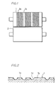
- Fig. 1 shows a pair of pressure rollers, namely, a pattern roller 1 and a flat roller 2.
- the pattern roller 1 has, on its peripheral surface, a plurality of hemispherical concavities 1a formed lengthwise and widthwise at regular intervals and each having a predetermined diameter.
- the flat roller 2 has a smooth surface. Portions each having a predetermined width L1 having the concavities 1a formed thereon are spaced at regular intervals of L2.
- the pattern roller 1 comprises the portions each having the width L1 for forming porous sheet sections 10 and the portions each having the width L2 for forming lead sections 11 consisting of solid portion.
- the concavities 1a are not formed on the flat roller 2, concaves may be formed thereon.
- the diameter and the length of the effective surface of each of the pattern roller 1 and the flat roller 2 are 150mm and 100mm, respectively.
- a vibrating device 4 vibrates a sieve 3 supported thereby and positioned above the pattern roller 1, in a left-and-right direction, having a mesh portion 3a formed on the bottom surface thereof.
- Metal powders (P) are spread over the upper surface of the pattern roller 1 by sieving them.
- a predetermined amount of metal powders (P) is supplied to the sieve 3 from a hopper 5 through a feeder 6 which feeds a predetermined quantity of the metal powders (P) per unit time period.
- Knives 7A and 7B are provided below a portion (A) of contact between the pattern roller 1 and the flat roller 2, with the knives 7A and 7B in contact with the peripheral surface of the pattern roller 1 and the flat roller 2, respectively.
- a suction device 8 for sucking metal powders which have remained on the peripheral surface of the pattern roller 1 is provided below the pattern roller 1 at the downstream side in the rotational direction of the pattern roller 1.
- nickel powders in the shape of spike and having diameters 2 - 7 ⁇ m are spread directly to the upper surface of the pattern roller 1 in the order of the hopper 5, the feeder 6, and the sieve 3.
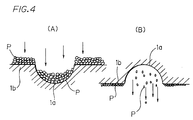
- the metal powders (P) which have dropped to the concaves 1a are prevented from being accumulated to the level of the peripheral surface 1b of the pattern roller 1, i.e., they do not project from the peripheral surface 1b.
- the metal powders (P) accumulate to a predetermined thickness on the peripheral surface 1b to form a layer having the predetermined thickness.
- the compressed metal sheet (S) thus formed at the contact point (A) becomes out of contact with the peripheral surface 1b of the pattern roller 1 and that of the flat roller 2, thus being fed downstream, as shown in Fig. 3. If the compressed metal sheet (S) has attached to the peripheral surface 1b of the pattern roller 1 or that of the flat roller 2, the knife 7A or the knife 7B releases it therefrom.
- the metal powders (P) accommodated inside the concaves 1a fall owing to their own weight caused by the rotation of the pattern roller 1. If they have remained in the concaves 1a, the suction device 8 sucks them. The metal powders (P) which have dropped from the concaves 1a and been sucked to the suction device 8 are returned to the hopper 5 and recycled so that the metal powders (P) are not wasted.
- the metal powders (P) are rolled by the pattern roller 1 and the flat roller 2 at the normal room temperature.
- the compressed metal sheet (S) formed by rolling the metal powders (P) and fed downstream from the contact point (A) comprises the porous sheet sections 10 corresponding to the portions of the pattern roller 1 having the width L1; and the belt-shaped lead sections 11 consisting of solid portion and corresponding to the portions of the pattern roller 1 having the width L2.
- Each of the porous sheet sections 10 comprises pores 13 corresponding to the concaves 1a of the pattern roller 1; and a portion 14 corresponding to the peripheral surface 1b of the pattern roller 1 and surrounding the pores 13.
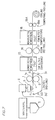
- the metal sheet (S) comprising the porous sheet sections 10 and the lead sections 11 alternating with each other is continuously fed into a sintering oven 15 in which it is sintered in a nonoxidizing atmosphere at 750°C for about 15 minutes.
- the metal sheet (S) was contracted by 1 - 2% as a result of the sintering.
- the metal sheet (S) After the metal sheet (S) is sintered, it is rolled as follows: It is passed through a pair of flat rollers 16 and 17 heated to 300°C - 400°C by applying a load of 5 tons thereto to roll it again. Then, the metal sheet (S) is continuously fed into a sintering oven 18 to sinter it again in a nonoxidizing atmosphere at 1,150°C for about 15 minutes, with the result that it was contracted by 0.1% - 0.2%.
- the metal sheet (S) After the metal sheet (S) is sintered in the sintering oven 18, it is passed between a pair of tempering rollers 19A and 19B to adjust the thickness of the metal sheet (S) to a predetermined thickness. Then, the metal sheet (S) is wound around a roller as a coil (C).
- the porous metal sheet which is preferably used as the electrode substrate of a battery is manufactured by the above-described process.
- the metal sheet of the first embodiment has a thickness of 30 ⁇ m and an open area ratio of 57%.
- the metal powders (P) are spread directly over the pattern roller 1 from the sieve 3.
- an inclined belt 20, a doctor knife 21, and a scraping knife 22 are provided. That is, the belt 20 is provided above the pattern roller 1 so as to supply the metal powders (P) from the hopper 5 to the belt 20.
- a predetermined amount of the metal powders (P) is supplied to the pattern roller 1 through the doctor knife 21 provided at an upper position of the belt 20 such that it is positioned alongside the belt 20.
- the scraping knife 22 provided at the lower end of the belt 20 such that it is positioned alongside the belt 20 is used to supply the metal powders (P) from the belt 20 to the upper surface of the pattern roller 1.
- Fig. 6 (B) similarly to the manner shown in Fig. 6 (A), it is possible to mix organic adhesive agent with the metal powders (P) in the hopper 5 to form paste and supply it to the belt 20; supply a predetermined amount of the metal powders (P) to the pattern roller 1 through the doctor knife 21; dry and degrease the paste by means of a drying means 23 installed at an intermediate position of the belt 20; and supply it to the upper surface of the pattern roller 1 through the scraping knife 22.
- a conduit 24 may be connected with the take-out opening of the hopper 5 at the lower end thereof.
- the conduit 24 is vibrated by a vibration means 25 to supply the metal powders (P) from the take-out opening of the hopper 5 to the upper surface of the pattern roller 1.
- Fig. 7 shows the second embodiment of the present invention.
- the pattern roller 1 and the flat roller 2 are vertically provided, with an endless steel conveyor belt 30 sandwiched therebetween.
- the sieve 3 of the first embodiment is provided at the upstream side of the pattern roller 1 and the flat roller 2 in the feeding direction so that the sieve 3 is vibrated to supply the metal powders (P) to the upper surface of the belt 30 in a predetermined thickness.
- the metal powders (P) supplied over the belt 30 have reached the contact point (A) between the rollers 1 and 2, they enter the concaves 1a and remain on the belt 30 without being compressed by the pattern roller 1, whereas the metal powders (P) which have dropped over the peripheral surface 1b of the pattern roller 1 are compressed and rolled at a load of 12 tons by the flat roller 2.
- the metal sheet(S) formed by rolling the metal powders (P) and having the porous sheet sections 10 and the lead sections 11 is fed downstream from the contact point (A).
- the metal powders (P) which are present on the concaves 1a are sucked by a suction device 31 installed on the belt 30 which is fed to the downstream side in the feeding direction of the compressed metal sheet (S).
- a suction device 31 installed on the belt 30 which is fed to the downstream side in the feeding direction of the compressed metal sheet (S).
- a cleaning roller 32 installed at the downstream side of the suction device 31 is brought into contact with the belt 30 to remove them therefrom.
- the metal powders (P) which have attached to the pattern roller 1 are removed therefrom by the suction device 8 and the knife 7. Because the metal powders (P) which have remained on the belt 30 and the pattern roller 1 are not compressed, they are recycled, similarly to the first embodiment.
- the metal sheet (S) formed by the rollers 1 and 2 and fed downstream from the contact point (A) is continuously fed into the sintering oven 15 to sinter it in a nonoxidizing atmosphere at 750°C for about 15 minutes.
- the metal sheet (S) was contracted by 2% - 3% as a result of the sintering.
- the metal sheet (S) is sintered, it is rolled as follows: It is passed through the flat rollers 16 and 17 by applying a load of 5 tons thereto to roll it again. Then, the metal sheet (S) is continuously fed into the sintering oven 18 to sinter it again in a nonoxidizing atmosphere at 1,150 °C for about 15 minutes, with the result that it was contracted by 0.5%.
- the porous metal sheet of the second embodiment thus formed has a thickness of 28 ⁇ m and an open area ratio of 57%.
- Figs. 8 (A) - 8 (C) show modifications of the method of supplying metal powders to the belt 30.
- the metal powders (P) are supplied directly to the upper surface of the belt 30 and the amount of the metal powders (P) is adjusted by a doctor knife 34 placed over the belt 30 so as to feed a constant amount thereof to the pattern roller 1 and 2.
- a doctor knife 34 placed over the belt 30 so as to feed a constant amount thereof to the pattern roller 1 and 2.
- Fig. 8 (B) it is possible to supply paste-like metal powders over the belt 30; adjust the amount thereof by means of the doctor knife 34; and dry and degrease it by means of a drying means 35; and supply it to the surface of the pattern roller 1 and 2.
- Fig. 8 (B) it is possible to supply paste-like metal powders over the belt 30; adjust the amount thereof by means of the doctor knife 34; and dry and degrease it by means of a drying means 35; and supply it to the surface of the pattern roller 1 and 2.
- a conduit 36 may be connected with the take-out opening of the hopper 5 at the lower end thereof to supply the metal powders (P) from the take-out opening of the hopper 5 to the belt 30.
- a knife 37 and a suction device 38 are installed over the peripheral surface of the pattern roller 1 to remove metal powders which have remained thereon.
- Figs. 9 (A) - 9 (D) show metal sheets manufactured by compression and rolling, with the concavities 1a formed on the pattern roller 1 shaped into quadrangular, hexagonal, rhombic, and triangular.
- Pores of a porous metal sheet S-1 shown in Fig. 9 (A) form the shape of a lattice
- Pores of a porous metal sheet S-2 shown in Fig. 9 (B) form the shape of a honeycomb
- Pores of a porous metal sheet S-3 shown in Fig. 9 (C) form the shape of a lath
- pores of a porous metal sheet S-4 shown in Fig. 9 (D) are in the shape of triangles arranged lengthwise and widthwise.
- the shape of pores to be formed on the porous metal sheet can be determined according to the shape of the concavities 1a formed on the pattern roller 1. Further, the open area ratio of the porous metal sheet can be adjusted to a desired one.
- the concaves 1a of the pattern roller 1 are rhombic.
- the hopper is supplied with electrolyzed branch-shaped copper powders having diameters 10-40 ⁇ m.
- the copper powders are supplied to the belt 30, with the doctor knife 34 adjusting the amount thereof to a predetermined amount so as to supply them in a predetermined amount directly to the upper surface of the pattern roller 1.
- the copper powders are compressed by the rollers 1 and 2 at the normal room temperature at a load of 4 tons.
- a metal sheet having pores in the shape of a lath is fed downstream, and sintered in a nonoxidizing atmosphere at 960°C for about 10 minutes. Then, it is passed through a pair of flat rollers by applying a load of 2 tons thereto to roll and temper it again.
- the resulting porous metal sheet has a thickness of 20 ⁇ m, an open area ratio of 40%, and tensile force of 2.5kgf/20mm.
- the third embodiment relates to a method of manufacturing a metal sheet having circular solid metal portions.
- a pattern roller 1' has, on its peripheral surface, a circular portion 1'c having a required shape; a concave portion 1'a shown by oblique lines; and a connection portion 1'd connecting the circular portions 1'c with each other.
- metal powders are dropped to the concave portion 1'a, and metal powders on the circular portion 1'c and the connection portion 1'd are compressed. As a result, a metal sheet S' having a circular solid metal portion 40 connected with a connection portion 41 is formed.
- the metal sheet S' is sintered and rolled by tempering rollers. The metal sheet S' manufactured by rolling and sintering is cut at the connection portion 41 thereof to provide a metal sheet S'' to be used as component parts of a circular battery, as shown in Fig. 10 (C).
- Fig. 11 shows a metal sheet S' manufactured as a modification of the metal sheet of the third embodiment by a method similar to that of the third embodiment.
- rectangular portions shown by oblique lines in Fig. 11 (A) are unrequired portions 45, and portions other than the unrequired portions 45 are cut as shown by one-dot chain line of Fig. 11 (A) to provide a metal sheet S'' to be used as an L-shaped lead of a battery consisting of a solid metal portion shown in Fig. 11 (B).
- the portions to be cut off from a material metal sheet is formed as pores on the pattern roller.
- a material can be used without wasting a large amount of metal.
- the metal sheet consisting of the solid portion can be allowed to be thin as desired.
- the metal sheet consisting of the solid portion can be preferably used in addition to component parts of a battery.
- the resulting metal sheet is sintered in the sintering oven 15; the sintered metal sheet is rolled again by the flat rollers 16 and 17; the rolled sheet is sintered again by the sintering oven 18.
- Metal powders of Au, Ag, Sn, Pb, In, and C are not required to be sintered, but may be only rolled.
- the porous metal sheet (S) or the metal sheet S' having the solid portion are formed by rolling metal powders at the normal room temperature by means of the pattern roller 1 and the flat roller 2.
- the metal sheet (S) or the metal sheet S' can be formed in various processes depending on the kind of metal powders.
- thin metal sheets can be processed from metal powders in appropriate combinations of the following six processes.
- the pattern roller 1 is heated to 300°C - 400°C previously and a predetermined amount of metal powders is supplied to the upper surface of the pattern roller 1, similarly to the first through third embodiments.
- the metal powders are rolled at the portion (A) of contact between the pattern roller 1 and the flat roller 2 at a load of 7 tons to form a metal sheet.
- the temperature of the atmosphere in which the roller is provided may be heated to 300°C - 400°C. Further, the surface of the pattern roller may be heated to a high temperature.
- a metal sheet may be manufactured by only rolling metal powders. Otherwise, as shown in Fig. 12, the metal sheet is sintered in a nonoxidizing atmosphere at 1,150°C for about 15 minutes, and tempered by the tempering rollers 19A and 19B to manufacture a porous metal sheet.
- the resulting porous metal sheet has a thickness of 34 ⁇ m and an open area ratio of 57%.
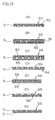
- Figs. 13 (A) - 13 (G) show metal sheets (SS) manufactured by the method according to the fourth embodiment.
- the metal sheets (SS) are formed by layering one or more sheets or two or more kinds of those sheets described below on one or both surfaces of the porous metal sheet (S) manufactured by the method of the first or second embodiment and then, by plating, evaporating or bonding the layered a sheet or sheets so as to integrate them with the porous metal sheet (S):
- a metal sheet (SS) having a layered structure shown in Fig. 13 is described below.
- a sheet of polyurethane sponge is bonded to one surface of the porous metal sheet (S) with adhesive agent. Then, the sheet of polyurethane sponge and the porous metal sheet (S) integrated therewith are plated and then, heated for resin removal and sintering to process the polyurethane sponge into the three-dimensional reticulate porous metal sheet 50 integrated with the metal sheet (S).
- the porous metal sheet (S) It is possible to laminate, on one surface of the porous metal sheet (S), the three-dimensional reticulate porous metal sheet 50 formed by plating and heating the three-dimensional reticulate foamed sheet of polyurethane sponge for resin removal and sintering, and then plating the layered sheet of the three-dimensional reticulate porous metal sheet 50 and the porous metal sheet (S) to integrate both sheets with each other.
- porous metal sheets formed by plating sheets described below and baking them for resin removal and sintering: Porous fibrous organic sheets made of synthetic resin, natural fiber, cellulose or paper having the shape of such as fabric, knit, nonwoven fabric, felt, screen, expanded, lath, punched pores-like; organic mesh sheets made of synthetic resin, natural fiber, cellulose or paper; inorganic sheets made of such as metal, glass, carbon or the like.
- sheets of polyurethane sponge is bonded to both surfaces of the metal sheet (S), and then, the metal sheet (S) and the two sheets of polyurethane sponge sandwiching it therebetween is plated.
- the three-dimensional reticulate porous metal sheet 50 is layered on both surfaces of the metal sheet (S). That is, because the metal sheet (S) having a high electric conductivity is positioned between the two sheets of polyurethane sponge, the electric conductivity becomes higher from both upper and lower surfaces toward the center thereof. Therefore, the two sheets of polyurethane sponge can be plated sufficiently into the interior in the thickness direction thereof unlike the conventional art.
- the porous metal sheet having the layered structure thus formed has a high strength because the metal sheet (S) is positioned at the center thereof. Thus, it has a high pulling strength, thus allowing an active substance to be applied thereto at a high speed. It is difficult to allow the porous metal sheet to have a high strength in increasing the open area ratio thereof when the amount of metal per area to be applied to polyurethane sponge is reduced and the diameters of skeletons surrounding pores are reduced. But it is possible to allow the porous metal sheet to have a required strength because the metal sheet (S) formed by rolling metal powders has a high strength.
- the mesh sheet used in place of the metal sheet (S) and polyurethane sponge are layered on each other, it is necessary to plate in an amount more than 300g/m 2 to the polyurethane sponge. But in layering the metal sheet (S) and the polyurethane sponge on each other, it is possible to reduce the amount of plating metal to be applied to the polyurethane sponge to 200g/m 2 . Thus, the open area ratio of the porous metal sheet can be increased.
- the plated metal sheet (SS) comprising polyurethane sponge sheets bonded to both surfaces of the metal sheet (S)
- the active substance-applied metal sheet (SS) having such a structure can be used as a high-quality electrode plate of a cylindrical battery, by coiling it, with the larger diameter-pore positioned at the peripheral side and with the smaller diameter-pore positioned at the inner peripheral side. In such an electrode plate, the active substance is not removed easily from the metal sheet (SS), and the metal sheet (SS) is not cracked easily.
- a metal sheet (SS) shown in Fig. 13 (B) a three-dimensional reticulate foamed sheet made of polyurethane sponge and a mesh sheet made of resin are layered on one surface of the porous metal sheet (S) formed by rolling metal powders by means of the pattern roller of the first embodiment, and a three-dimensional reticulate foamed sheet made of polyurethane sponge is layered on the other surface thereof. Then, the four sheets layered on each other are plated.
- the metal sheet (SS) comprises the metal sheet (S), a porous metal sheet 51 consisting of a three-dimensional reticulate porous metal sheet and a metal mesh sheet positioned on one surface of the metal sheet (S), and the three-dimensional reticulate porous metal sheet 50 positioned on the other surface thereof, with the four sheets layered on each other.
- a metal sheet (SS) shown in Fig. 13 (C) is formed as follows: metal powders are attached to surface of a sheet made of a three-dimensional reticulate foamed sheet made of polyurethane sponge and the sheet is baked for resin removal and sintering to form a porous metal sheet 52. Similarly, metal powders are attached to a nonwoven sheet, and the sheet is baked for resin removal and sintering to form a porous metal sheet 53.
- the porous metal sheet 52 is layered on one surface of the porous metal sheet (S) formed by rolling metal powders with the pattern roller of the first embodiment, and the porous metal sheet 53 is layered on the other surface thereof. Then, the layered sheets are plated to form the metal sheet (SS) consisting of the three sheets integrated with each other.
- the metal powders ultra-fine metal ones flake-shaped ones and/or metal powders crushed can be preferably used.
- the metal sheet (SS) can be formed as follows: The three-dimensional reticulate foamed sheet is layered on one surface of the metal sheet (S), and the nonwoven sheet is layered on the other surface thereof and then, the metal powders are attached to both the three-dimensional reticulate foamed sheet and the nonwoven sheet, and then, the three sheets layered on each other are baked for resin removal and sintering to form a layered sheet comprising the metal sheet (S), the three-dimensional reticulate porous metal sheet, and the nonwoven sheet-like porous metal sheet. Further, the porous metal sheet consisting of the three sheets layered on each other may be electroplated again.
- a metal sheet (SS) shown in Fig. 13 (D) having a layered structure is formed as follows. That is, a nonwoven sheet is layered on one surface of the porous metal sheet (S) formed by the first embodiment, and then the nonwoven sheet is coated with sprayed melted metal. Then, the two sheets layered one on the other is baked for resin removal and sintering.
- the porous metal sheet (S) and the nonwoven sheet-like porous metal sheet 54 layered thereon are plated to form the metal sheet (SS) consisting of the two sheets integrated with each other.
- a metal sheet (SS) having a layered structure shown in Fig. 13 (E) is formed as follows: A nonwoven fabric-like porous metal sheet 55 formed of metal fibers consisting of metal powders is layered on both surfaces of the porous metal sheet (S) formed by the first embodiment. Then, the three sheets layered on each other as described above are plated.
- metal fibers made of metal powder it is possible to use a nonwoven fabric-like porous metal sheet consisting of metal fibers formed by convergent drawing method, metal fiber spinning method, metal foil cutting method. Further, it is possible to use a nonwoven fabric-like porous metal sheet consisting of metal fibers formed by cutting a metal rod or a coiled metal foil by chatter vibration cutting method.
- the metal sheet (SS) consisting of the nonwoven fabric-like porous metal sheet 55 consisting of fine or small-diameter metal fibers and the metal sheet (S) formed by the first embodiment and layered thereon has a high strength and a high open area ratio. Further, because the metal sheet (S) has a high strength and a high electric conductivity, the layered metal sheet (SS) has a high electric conductivity. Therefore, the metal sheet (SS) has a high open area ratio and moreover, has a high pulling strength.
- a metal sheet (SS) having a layered structure shown in Fig. 13 (F) is formed as follows: Through the intermediary of a screen, slurry-like fine metal powders are applied to a base film. Then, the base film is baked, treated with chemicals or exfoliate to remove it from the fine metal powders. Then, the metal powders are sintered to form a porous metal sheet 56. Then, the porous metal sheet 56 is layered on one surface of the porous metal sheet (S) formed by the first embodiment. Then, the porous metal sheet (S) and the porous metal sheet 56 layered thereon are plated to form the metal sheet (SS).
- a metal sheet (SS) having a layered structure shown in Fig. 13 (G) is formed as follows: Two porous metal sheets (S) formed by the first embodiment are layered on each other and are then plated.
- porous metal sheets to be layered on and integrated with the porous metal sheet (S) formed by the first embodiment it is possible to use a porous metal sheet having a large number of pores formed thereon by performing punching processing, lath processing or expanded processing on a metal plate or a metal foil, a solid metal plate, a solid metal foil, a metal mesh sheet, a metal screen or a porous metal sheet formed by electro-coating them by using coating including metal powders, and then baking them for resin removal and sintering; a porous metal sheet formed by applying metal powders to a three-dimensional reticulate sheet by using adhesive agent and baking the sheet for resin removal and sintering; or a porous metal sheet formed by forming an electrically conductive metal layer consisting of fine metal powders applied to a three-dimensional reticulate sheet by using adhesive agent and then plating the sheet and then baking the sheet for resin removal and sintering.
- the metal sheet consisting of the metal sheet (S) and two same three-dimensional reticulate porous metal sheets by bonding sheets of polyurethane sponge to both surfaces of the metal sheet (S), and then, plating the metal sheet (S) and the two sheets of polyurethane sponge or by plating the sheets of polyurethane sponge and then layering each plated sheet on each surface of the metal sheet (S), it is possible to differentiate the pulling strengths of both three-dimensional reticulate porous metal sheets from each other by altering the diameter of pores thereof, the open area ratio thereof, and the thickness of skeleton surrounding the open area. The same is the case with nonwoven fabric-like porous metal sheets which are bonded to both surface of the metal sheet (S).
- the metal sheet having the layered structure and an active substance applied thereto is spirally coiled to use it as the electrode plate of a battery, it is preferable to position the three-dimensional reticulate porous metal sheet having the larger diameter-pore at the outer peripheral side and the one having the smaller diameter-pore at the inner peripheral side so that the outer side of the metal sheet can be stretched in coiling it and consequently, the occurrence of crack can be reduced or prevented.
- Evaporation, fusing or any appropriate method can be used in addition to plating as the method of integrating the metal sheet (S) formed by rolling metal powders by means of the pattern roller with various kinds of porous metal sheets, various kinds of metal plates or various kinds of metal foils.
- the porous metal sheet formed by above-mentioned methods is cut to required sizes and an active substance is applied thereto to use them as the electrode plate of a nickel hydrogen battery, a nickel cadmium battery or the like. Because the electrode plate of the present invention is thinner than the conventional one, it can be accommodated in a battery in an amount more than the conventional one, thus improving the capability thereof. Further, the open area ratio of the electrode substrate can be adjusted as desired. Furthermore, the open area ratio of the substrate can be increased without wasting a material and thus the substrate can be manufactured at a low cost.
- a solid metal plate or a solid metal foil may be fused into one surface or both surfaces of the metal sheet of the first or second embodiment to form a metal sheet having a layered structure.
- a metal sheet having a layered structure may be manufactured by plating the solid metal plate or the solid metal foil layered on one surface or both surfaces of the metal sheet of the first or second embodiment.
- the metal sheet consisting of the solid metal plate or foil layered on the metal sheet of the first or second embodiment can be used as the electrode substrate of a lithium secondary battery.
- concaves of a required pattern are formed on the pattern roller of a pair of rollers.
- those which have dropped to the concaves are not rolled but those which have dropped to the concave-unprovided portion of the peripheral surface of the pattern roller are compressed.
- a metal sheet formed of metal powders is rolled, sintered, repeatedly, then tempered as necessary. In this manner, a porous metal sheet having pores having a required shape formed thereon is manufactured.
- the porous metal sheet obtained by the method is thinner than the one obtained by the conventional method of punching a metal sheet to form pores thereon.
- the porous metal sheet is used as an electrode substrate, the amount of metal powders to be used for a material per centiare can be reduced because the porous metal sheet is thin.
- the porous metal sheet can be manufactured at a low cost.
- the porous metal sheet can be accommodated in a battery in an amount more than the conventional one, thus improving the capability thereof.
- the porous metal sheet consists of metal powders, it has a high electrical conductivity. Thus, when it is used as an electrode plate, it improves the capability of a battery. Because the porous metal sheet has a high pulling strength, the manufacturing line thereof can be operated at a high speed. Therefore, the porous metal sheet can be produced at a high efficiency and thus at a low cost.
- the method of the present invention eliminates the need for the provision of a punching process and a plating process required in manufacturing a punching metal, thus allowing the porous metal sheet to be manufactured in a simple process and hence at a low cost. Moreover, metal powders which have dropped to the concaves of the peripheral surface of the pattern roller are not compressed by the flat roller, thus being recycled without wasting metal powders, which leads to the reduction in manufacturing cost.
- metal is used in the form of powder, they can be compresses and united each other under pressure at a temperature lower than the melting point of a metal even though the melting point is high.
- mixed with other kinds of metals Accordingly, a porous metal sheet or a solid metal sheet can be obtained from a required kind of metal, the oxide thereof, the sulfide thereof, a simple substrate containing a compound of the metal or a mixture thereof.
- the metal sheet obtained by rolling metal powders by means of a pair of the rollers including the pattern roller is thin, the thickness thereof can be adjusted to a required one even though the metal sheet and porous metal sheets are layered on each other.
- the metal sheet of the present invention can be preferably used.
- the entire sheet thus formed has a high strength because the metal sheet having a high pulling strength is positioned at the center thereof. Thus, it has a high pulling strength, thus allowing an active substance to be applied thereto at a high speed.
- a layered structure consisting of foamed sheets of polyurethane sponge or the like, porous fibrous sheets of resin or mesh sheets layered on both surfaces of the metal sheet manufactured by using the pattern roller are plated, the electric conductivity from the peripheral side of the entire sheet toward the center thereof is allowed to be favorable.
- the foamed sheets or the mesh sheets can be plated into the interior in the thickness direction thereof. That is, the entire metal sheet having the layered structure has a high electrical conductivity, thus increasing the performance of a battery when an active substance-applied metal sheet is used as an electrode plate of the battery.
Landscapes
- Chemical & Material Sciences (AREA)
- Engineering & Computer Science (AREA)
- Chemical Kinetics & Catalysis (AREA)
- Electrochemistry (AREA)
- General Chemical & Material Sciences (AREA)
- Manufacturing & Machinery (AREA)
- Mechanical Engineering (AREA)
- Composite Materials (AREA)
- Materials Engineering (AREA)
- Cell Electrode Carriers And Collectors (AREA)
- Powder Metallurgy (AREA)
Description
Claims (16)
- A method of manufacturing a porous metal sheet (S) having pores (13) forming a pattern, comprising the steps of:supplying metal powders (P) to a peripheral surface of at least one pattern roller (1) of a pair of rollers (1, 2), on which a pattern consisting of a large number of concavities (1a) is formed;dropping the metal powders to the concavities and accumulating the metal powders on the peripheral surface of the pattern roller except the concavities;and rolling directly the metal powders accumulated on the peripheral surface of the pattern roller by rotating the pair of rollers.
- A method of manufacturing a porous metal sheet (S'; S'') having a metal solid portion (40) having a required shape, comprising the steps of:supplying metal powders (P) to a peripheral surface of at least one pattern roller (1) of a pair of rollers (1, 2), on which a pattern consisting of a large number of concavities (1'a) is formed on a portion except a portion (1'c) of a required shape;dropping the metal powders to the concavities and accumulating the metal powders on the peripheral surface of the pattern roller except the concavities; androlling directly the metal powders accumulated on the peripheral surface of the pattern roller by rotating the pair of rollers.
- The method according to claim 1 or 2, wherein at least one of the pair of the rollers is heated previously, and the metal powders (P) are rolled on the heated roller.
- The method according to any one of claims 1 through 3, wherein after the metal powders are rolled by the pair of rollers including the pattern roller (1), the metal powders are rolled again by a pair of flat rollers (16, 17) having a smooth peripheral surface.
- The method according to claim 4, wherein the pair of flat rollers (16, 17) are heated.
- The method according to any one of claims 1 through 5, wherein the metal powders are sintered after the metal powders are rolled by the pair of rollers (1, 2) including the pattern roller and/or the pair of flat rollers (16, 17).
- The method according to any one of claims 1 through 6, wherein the metal powders are rolled again by a pair of flat rollers (19A, 19B) having a smooth peripheral surface after the metal powders are rolled by the pair of the rollers (1, 2,) including the pattern roller or the pair of the flat rollers (16, 17) or after the metal powders are sintered.
- A method of manufacturing a porous metal sheet (SS), comprising the steps of:layering, on at least one surface of a metal sheet (S) manufactured by the method according to any one of claims 1 through 7, one or more of the following sheets : a metal sheet (S) manufactured by the method according to any one of claims 1 through 7, a porous metal sheet (50; 51; 52; 53; 54; 55; 56), a solid metal sheet, a solid metal foil, a metal sheet or a metal foil each having a large number of pores formed thereon, a metal mesh sheet, a metal screen, a threedimensional reticulate foamed sheet, a porous fibrous resin sheet, a mesh sheet, and/or a porous metal sheet which is manufactured by baking the sheet to remove resin and sintering after plating, evaporating, coating fine metal powders or spray-coating melted metal a three-dimensional reticulated foamed sheet, a porous fibrous resin sheet, a mesh sheet, a sheet composed by layering those sheets on each other or two or more kinds of those sheets; andintegrating the sheet or the sheets with the metal sheet (S) manufactured by the method according to any one of claims 1 through 7 by plating or evaporating the sheets layered on the metal sheet or bonding the sheets to each other.
- A metal sheet (S; SS) manufactured by the method described in any one of claims 1 through 8.
- A metal sheet of an electrode substrate of a battery manufactured by the method described in any one of claims 1 through 8.
- The metal sheet according to claim 9 or 10, wherein the metal powder constituting the metal sheet consists of Ni, Al, Cu, Fe, Ag, Zn, Sn, Pb, Sb, Ti, In, V, Cr, Co, C, Ca, Mo, Au, P, W, Rh, the oxide thereof, the sulfide thereof, a compound thereof or a mixture of those metals.
- The metal sheet according to any one of claims 9 through 11, wherein the metal sheet having pores forming a pattern is punched pore-shaped, reticulate, honeycomb-shaped, lath-shaped, lattice-shaped, expanded-shaped, screen-shaped or lace-shaped.
- The metal sheet according to claim 12, wherein the metal sheet has a lead portion (11) in which pores are not formed, or a plurality of such lead portions at regular intervals.
- The metal sheet according to any one of claims 9 through 13, wherein a three-dimensional reticulate porous metal sheet (50) or a porous fibrous metal sheet is layered on both surfaces of the metal sheet (S) manufactured according to any one of claims 1 through 8; the metal sheet (S) is sandwiched between the two three-dimensional reticulate porous metal sheets (50) or between the two porous fibrous metal sheets; and a diameter of a pore, an open area ratio, and/or a diameter of a metal fiber of the three-dimensional reticulate porous metal sheet or those of the porous fibrous metal sheet layered on one surface of the metal sheet (S) are different from those of the three-dimensional reticulate porous metal sheet or those of the porous fibrous metal sheet layered on the other surface thereof.
- A battery comprising the metal sheet described in any one of Claims 9 through 14 used as an electrode substrate.
- Use of a roller (1) having a pattern having concavities (1a) formed thereon in a manufacturing process as defined in any one of the claims 1 through 8.
Applications Claiming Priority (3)
| Application Number | Priority Date | Filing Date | Title |
|---|---|---|---|
| JP12253496 | 1996-04-19 | ||
| JP08122534A JP3080297B2 (en) | 1996-04-19 | 1996-04-19 | Method for producing metal sheet and metal sheet produced by the method |
| JP122534/96 | 1996-04-19 |
Publications (2)
| Publication Number | Publication Date |
|---|---|
| EP0802005A1 EP0802005A1 (en) | 1997-10-22 |
| EP0802005B1 true EP0802005B1 (en) | 2000-08-02 |
Family
ID=14838246
Family Applications (1)
| Application Number | Title | Priority Date | Filing Date |
|---|---|---|---|
| EP97106485A Expired - Lifetime EP0802005B1 (en) | 1996-04-19 | 1997-04-18 | Method of manufacturing a porous metal sheet having pores forming a pattern |
Country Status (8)
| Country | Link |
|---|---|
| US (1) | US5850591A (en) |
| EP (1) | EP0802005B1 (en) |
| JP (1) | JP3080297B2 (en) |
| KR (1) | KR970069167A (en) |
| CN (1) | CN1180906C (en) |
| CA (1) | CA2202694A1 (en) |
| DE (1) | DE69702680T2 (en) |
| TW (1) | TW381048B (en) |
Cited By (2)
| Publication number | Priority date | Publication date | Assignee | Title |
|---|---|---|---|---|
| EP4360778A4 (en) * | 2021-06-25 | 2024-10-23 | Toho Titanium CO., LTD. | Titanium porous body and titanium porous body manufacturing method |
| EP4400633A4 (en) * | 2021-09-09 | 2025-12-24 | Qingke New Energy Tech Shanghai Co Ltd | GAS DIFFUSION LAYER AND MANUFACTURING METHOD FOR IT |
Families Citing this family (23)
| Publication number | Priority date | Publication date | Assignee | Title |
|---|---|---|---|---|
| JP3481797B2 (en) * | 1996-10-03 | 2003-12-22 | 片山特殊工業株式会社 | Method for manufacturing battery electrode substrate and battery electrode substrate |
| JP3004246B2 (en) * | 1997-03-24 | 2000-01-31 | 片山特殊工業株式会社 | Method for producing metal sheet, metal sheet produced by the method, method for producing electrode for battery, and electrode for battery |
| JP3508604B2 (en) * | 1998-04-08 | 2004-03-22 | 三菱マテリアル株式会社 | Method for producing high-strength sponge-like fired metal composite plate |
| DE60033076T2 (en) * | 1999-04-16 | 2007-08-30 | Matsushita Electric Industrial Co., Ltd., Kadoma | Anodic electrode for electrolytic capacitor and process for its preparation |
| AU1749701A (en) * | 1999-12-28 | 2001-07-09 | Akzo Nobel N.V. | Method and construction for ventilation of hydrogen gas |
| JP5015991B2 (en) * | 2008-11-11 | 2012-09-05 | トーカロ株式会社 | Printing roll and method for producing the same |
| WO2010116872A1 (en) * | 2009-04-10 | 2010-10-14 | 三菱電機株式会社 | Electric storage device electrode and method for manufacturing same |
| EP2474060A1 (en) * | 2009-09-04 | 2012-07-11 | G4 Synergetics, Inc. | Methods for forming foamed electrode structures |
| JP2013057100A (en) * | 2011-09-08 | 2013-03-28 | Ihi Corp | Powder rolling apparatus |
| US20140170012A1 (en) * | 2012-12-18 | 2014-06-19 | United Technologies Corporation | Additive manufacturing using partially sintered layers |
| CN103350323B (en) * | 2013-06-20 | 2015-10-07 | 上海龙人建设集团有限公司 | The manufacture method of torsional deformation metal finishing band |
| KR101945437B1 (en) | 2016-12-22 | 2019-02-11 | 주식회사 미트 | Metal air fuel cell including roll anode |
| CN106583732A (en) * | 2017-02-15 | 2017-04-26 | 天津中钢联科技发展有限公司 | Hot-rolled steel plate production device |
| CN106935794B (en) * | 2017-03-15 | 2019-08-06 | 陈熙野 | A kind of preparation method for copper electrode of gilding |
| US11486030B2 (en) | 2018-05-23 | 2022-11-01 | Molecule Works Inc. | Process and apparatus for continuous production of porous structures |
| CN109333374A (en) * | 2018-12-03 | 2019-02-15 | 山西太钢不锈钢股份有限公司 | Surface oxide removal method of steel plate |
| CN110814333B (en) * | 2019-11-20 | 2021-11-26 | 江苏铭亚科技有限公司 | Metal powder smelting recovery processing device and process thereof |
| CN110722164B (en) * | 2019-11-29 | 2020-09-29 | 西北有色金属研究院 | Preparation method for improving uniformity of large-size powder rolled metal porous plate |
| DE102020101975A1 (en) * | 2020-01-28 | 2021-07-29 | Bfc Fahrzeugteile Gmbh | METAL STRAP |
| KR102819127B1 (en) | 2020-03-31 | 2025-06-12 | 주식회사 엘지에너지솔루션 | High Voltage Busbar Having Dissimilar Metals and Manufacturing Method Thereof |
| CN111618293B (en) * | 2020-06-08 | 2021-06-01 | 北京科技大学 | Method for preparing copper-iron alloy net by powder rolling process |
| CN116601782A (en) * | 2020-12-08 | 2023-08-15 | 应用材料公司 | Pre-lithiated and lithium metal-free anode coatings |
| CN121131418B (en) * | 2025-11-17 | 2026-04-17 | 太原理工大学 | Electric field auxiliary rolling device and conductive equipment |
Family Cites Families (16)
| Publication number | Priority date | Publication date | Assignee | Title |
|---|---|---|---|---|
| US2222251A (en) * | 1938-03-04 | 1940-11-19 | Chrysler Corp | Method of making porous metal structures and bearings |
| GB648929A (en) * | 1948-03-25 | 1951-01-17 | Mond Nickel Co Ltd | Improvements relating to the production of porous metal plates |
| US2979400A (en) * | 1959-02-04 | 1961-04-11 | Purolator Products Inc | Porous media |
| US3002834A (en) * | 1960-02-24 | 1961-10-03 | Yardney International Corp | Process for producing electrode plates |
| FR1320812A (en) * | 1961-01-30 | 1963-03-15 | Mond Nickel Co Ltd | Improvements in electrode production |
| US3390968A (en) * | 1964-08-28 | 1968-07-02 | Union Carbide Corp | High density tungsten compacts and method of making same |
| US3422515A (en) * | 1966-05-23 | 1969-01-21 | Mallory & Co Inc P R | Method for making porous electrodes comprising freezing wet powder and sintering |
| US3431105A (en) * | 1968-02-12 | 1969-03-04 | Kempf Gmbh Karl | Process for manufacturing parts provided with a sintered surface layer |
| CA962326A (en) * | 1970-11-05 | 1975-02-04 | Sherritt Gordon Mines Limited | Process for making porous electrode plates |
| US4059879A (en) * | 1975-11-17 | 1977-11-29 | Textron Inc. | Method for the controlled mechanical working of sintered porous powder metal shapes to effect surface and subsurface densification |
| US4108651A (en) * | 1976-05-24 | 1978-08-22 | Tapley Claude D | Method of producing a multi-gage strip or shape from powdered metal |
| DE3509616C2 (en) * | 1985-02-27 | 1987-04-30 | Korf Engineering GmbH, 4000 Düsseldorf | Method for compacting iron particles and subsequent breaking apart of the compacted iron strip and device for carrying out this method |
| US4654195A (en) * | 1985-12-23 | 1987-03-31 | International Fuel Cells Corporation | Method for fabricating molten carbonate ribbed anodes |
| US4820481A (en) * | 1988-04-25 | 1989-04-11 | Energy Conversion Devices, Inc. | Method for the continuous fabrication of hydrogen storage alloy negative electrodes |
| CA2131872A1 (en) * | 1993-09-14 | 1995-03-15 | Hirofumi Sugikawa | Metallic porous sheet and method for manufacturing same |
| JP3509031B2 (en) * | 1993-12-10 | 2004-03-22 | 片山特殊工業株式会社 | Method for manufacturing porous metal body with lead and porous metal body with lead manufactured by the method |
-
1996
- 1996-04-19 JP JP08122534A patent/JP3080297B2/en not_active Expired - Lifetime
-
1997
- 1997-04-09 TW TW086104548A patent/TW381048B/en not_active IP Right Cessation
- 1997-04-15 CA CA002202694A patent/CA2202694A1/en not_active Abandoned
- 1997-04-17 CN CNB971101205A patent/CN1180906C/en not_active Expired - Fee Related
- 1997-04-18 DE DE69702680T patent/DE69702680T2/en not_active Expired - Fee Related
- 1997-04-18 US US08/837,457 patent/US5850591A/en not_active Expired - Lifetime
- 1997-04-18 KR KR1019970014419A patent/KR970069167A/en not_active Withdrawn
- 1997-04-18 EP EP97106485A patent/EP0802005B1/en not_active Expired - Lifetime
Cited By (2)
| Publication number | Priority date | Publication date | Assignee | Title |
|---|---|---|---|---|
| EP4360778A4 (en) * | 2021-06-25 | 2024-10-23 | Toho Titanium CO., LTD. | Titanium porous body and titanium porous body manufacturing method |
| EP4400633A4 (en) * | 2021-09-09 | 2025-12-24 | Qingke New Energy Tech Shanghai Co Ltd | GAS DIFFUSION LAYER AND MANUFACTURING METHOD FOR IT |
Also Published As
| Publication number | Publication date |
|---|---|
| JP3080297B2 (en) | 2000-08-21 |
| CA2202694A1 (en) | 1997-10-19 |
| DE69702680D1 (en) | 2000-09-07 |
| KR970069167A (en) | 1997-11-07 |
| EP0802005A1 (en) | 1997-10-22 |
| DE69702680T2 (en) | 2001-03-29 |
| CN1180906C (en) | 2004-12-22 |
| JPH09287006A (en) | 1997-11-04 |
| TW381048B (en) | 2000-02-01 |
| US5850591A (en) | 1998-12-15 |
| CN1175488A (en) | 1998-03-11 |
Similar Documents
| Publication | Publication Date | Title |
|---|---|---|
| EP0802005B1 (en) | Method of manufacturing a porous metal sheet having pores forming a pattern | |
| US6436580B1 (en) | Method of manufacturing porous sheet, porous metal sheet manufactured by method, and electrode for battery | |
| CN1130785C (en) | Manufacturing method of substrate for battery electrode and substrate for battery electrode | |
| EP0717457B1 (en) | Porous metallic sheet used as an electrode substrate of a battery and method of manufacturing the porous metallic sheet | |
| KR100583132B1 (en) | Method of producing electrode for battery and electrode produced by method | |
| US6485865B1 (en) | Porous metal sheet, battery electrode plate composed of porous metal sheet and battery having electrode plate | |
| US5508114A (en) | Lead-provided porous metal sheet and method for manufacturing the sheet | |
| EP0867248A1 (en) | Method of manufacturing porous metal sheet and metal sheet manufactured by this method | |
| EP0864389B1 (en) | Method for manufacturing porous sheet, porous metal sheet manufactured by this method, and electrode for battery | |
| EP0813261A2 (en) | Metal sheet for electrode substrate of battery can | |
| JPH09143510A (en) | Metallic fiber porous body for battery electrode substrate, battery electrode substrate and its production | |
| JPH09147850A (en) | Manufacture of hydrogen storage alloy electrode | |
| CA2254640A1 (en) | Method of manufacturing a porous metallic sheet for use as an electrode substrate of a battery |
Legal Events
| Date | Code | Title | Description |
|---|---|---|---|
| PUAI | Public reference made under article 153(3) epc to a published international application that has entered the european phase |
Free format text: ORIGINAL CODE: 0009012 |
|
| AK | Designated contracting states |
Kind code of ref document: A1 Designated state(s): BE DE FR GB IT NL |
|
| 17P | Request for examination filed |
Effective date: 19971120 |
|
| GRAG | Despatch of communication of intention to grant |
Free format text: ORIGINAL CODE: EPIDOS AGRA |
|
| 17Q | First examination report despatched |
Effective date: 19990930 |
|
| GRAG | Despatch of communication of intention to grant |
Free format text: ORIGINAL CODE: EPIDOS AGRA |
|
| GRAH | Despatch of communication of intention to grant a patent |
Free format text: ORIGINAL CODE: EPIDOS IGRA |
|
| GRAH | Despatch of communication of intention to grant a patent |
Free format text: ORIGINAL CODE: EPIDOS IGRA |
|
| GRAA | (expected) grant |
Free format text: ORIGINAL CODE: 0009210 |
|
| AK | Designated contracting states |
Kind code of ref document: B1 Designated state(s): BE DE FR GB IT NL |
|
| ITF | It: translation for a ep patent filed | ||
| REF | Corresponds to: |
Ref document number: 69702680 Country of ref document: DE Date of ref document: 20000907 |
|
| ET | Fr: translation filed | ||
| PGFP | Annual fee paid to national office [announced via postgrant information from national office to epo] |
Ref country code: NL Payment date: 20010430 Year of fee payment: 5 |
|
| PLBE | No opposition filed within time limit |
Free format text: ORIGINAL CODE: 0009261 |
|
| STAA | Information on the status of an ep patent application or granted ep patent |
Free format text: STATUS: NO OPPOSITION FILED WITHIN TIME LIMIT |
|
| 26N | No opposition filed | ||
| REG | Reference to a national code |
Ref country code: GB Ref legal event code: IF02 |
|
| PG25 | Lapsed in a contracting state [announced via postgrant information from national office to epo] |
Ref country code: NL Free format text: LAPSE BECAUSE OF NON-PAYMENT OF DUE FEES Effective date: 20021101 |
|
| NLV4 | Nl: lapsed or anulled due to non-payment of the annual fee |
Effective date: 20021101 |
|
| PG25 | Lapsed in a contracting state [announced via postgrant information from national office to epo] |
Ref country code: IT Free format text: LAPSE BECAUSE OF NON-PAYMENT OF DUE FEES Effective date: 20050418 |
|
| PGFP | Annual fee paid to national office [announced via postgrant information from national office to epo] |
Ref country code: DE Payment date: 20080424 Year of fee payment: 12 |
|
| PGFP | Annual fee paid to national office [announced via postgrant information from national office to epo] |
Ref country code: BE Payment date: 20080416 Year of fee payment: 12 |
|
| PGFP | Annual fee paid to national office [announced via postgrant information from national office to epo] |
Ref country code: FR Payment date: 20080317 Year of fee payment: 12 |
|
| PGFP | Annual fee paid to national office [announced via postgrant information from national office to epo] |
Ref country code: GB Payment date: 20080418 Year of fee payment: 12 |
|
| BERE | Be: lapsed |
Owner name: *KATAYAMA SPECIAL INDUSTRIES LTD Effective date: 20090430 |
|
| GBPC | Gb: european patent ceased through non-payment of renewal fee |
Effective date: 20090418 |
|
| REG | Reference to a national code |
Ref country code: FR Ref legal event code: ST Effective date: 20091231 |
|
| PG25 | Lapsed in a contracting state [announced via postgrant information from national office to epo] |
Ref country code: DE Free format text: LAPSE BECAUSE OF NON-PAYMENT OF DUE FEES Effective date: 20091103 |
|
| PG25 | Lapsed in a contracting state [announced via postgrant information from national office to epo] |
Ref country code: GB Free format text: LAPSE BECAUSE OF NON-PAYMENT OF DUE FEES Effective date: 20090418 Ref country code: FR Free format text: LAPSE BECAUSE OF NON-PAYMENT OF DUE FEES Effective date: 20091222 |
|
| PG25 | Lapsed in a contracting state [announced via postgrant information from national office to epo] |
Ref country code: BE Free format text: LAPSE BECAUSE OF NON-PAYMENT OF DUE FEES Effective date: 20090430 |