EP0801748B1 - Reduced power selective excitation rf pulses - Google Patents
Reduced power selective excitation rf pulses Download PDFInfo
- Publication number
- EP0801748B1 EP0801748B1 EP95927474A EP95927474A EP0801748B1 EP 0801748 B1 EP0801748 B1 EP 0801748B1 EP 95927474 A EP95927474 A EP 95927474A EP 95927474 A EP95927474 A EP 95927474A EP 0801748 B1 EP0801748 B1 EP 0801748B1
- Authority
- EP
- European Patent Office
- Prior art keywords
- pulse
- pulse sequence
- pulses
- total energy
- frequency dependent
- Prior art date
- Legal status (The legal status is an assumption and is not a legal conclusion. Google has not performed a legal analysis and makes no representation as to the accuracy of the status listed.)
- Expired - Lifetime
Links
- 230000005284 excitation Effects 0.000 title claims abstract description 40
- 238000001208 nuclear magnetic resonance pulse sequence Methods 0.000 claims abstract description 69
- 238000000034 method Methods 0.000 claims abstract description 54
- 230000004044 response Effects 0.000 claims abstract description 50
- 230000005415 magnetization Effects 0.000 claims abstract description 31
- 230000001419 dependent effect Effects 0.000 claims description 31
- 230000002194 synthesizing effect Effects 0.000 claims description 17
- 238000003384 imaging method Methods 0.000 claims description 14
- 230000009467 reduction Effects 0.000 claims description 11
- 238000004364 calculation method Methods 0.000 claims description 4
- 238000013421 nuclear magnetic resonance imaging Methods 0.000 claims description 2
- 238000013461 design Methods 0.000 abstract description 11
- 230000015572 biosynthetic process Effects 0.000 abstract description 8
- 238000003786 synthesis reaction Methods 0.000 abstract description 8
- 238000002595 magnetic resonance imaging Methods 0.000 abstract description 5
- 238000010521 absorption reaction Methods 0.000 abstract description 3
- 230000008859 change Effects 0.000 abstract description 3
- 230000000593 degrading effect Effects 0.000 abstract 1
- 230000002045 lasting effect Effects 0.000 description 9
- 230000000694 effects Effects 0.000 description 8
- 238000013459 approach Methods 0.000 description 7
- 238000005481 NMR spectroscopy Methods 0.000 description 5
- 238000012986 modification Methods 0.000 description 4
- 230000004048 modification Effects 0.000 description 4
- 238000005316 response function Methods 0.000 description 4
- 230000008901 benefit Effects 0.000 description 2
- 238000009472 formulation Methods 0.000 description 2
- 238000010438 heat treatment Methods 0.000 description 2
- 239000011159 matrix material Substances 0.000 description 2
- 239000000203 mixture Substances 0.000 description 2
- 230000008569 process Effects 0.000 description 2
- 238000001228 spectrum Methods 0.000 description 2
- 238000004458 analytical method Methods 0.000 description 1
- 238000006243 chemical reaction Methods 0.000 description 1
- 238000003759 clinical diagnosis Methods 0.000 description 1
- 230000003287 optical effect Effects 0.000 description 1
- 238000005457 optimization Methods 0.000 description 1
- 230000003094 perturbing effect Effects 0.000 description 1
- 238000010845 search algorithm Methods 0.000 description 1
- 238000004611 spectroscopical analysis Methods 0.000 description 1
- 238000012360 testing method Methods 0.000 description 1
- 230000007704 transition Effects 0.000 description 1
- 239000013598 vector Substances 0.000 description 1
Images


Classifications
-
- G—PHYSICS
- G01—MEASURING; TESTING
- G01R—MEASURING ELECTRIC VARIABLES; MEASURING MAGNETIC VARIABLES
- G01R33/00—Arrangements or instruments for measuring magnetic variables
- G01R33/20—Arrangements or instruments for measuring magnetic variables involving magnetic resonance
- G01R33/44—Arrangements or instruments for measuring magnetic variables involving magnetic resonance using nuclear magnetic resonance [NMR]
- G01R33/446—Multifrequency selective RF pulses, e.g. multinuclear acquisition mode
-
- G—PHYSICS
- G01—MEASURING; TESTING
- G01R—MEASURING ELECTRIC VARIABLES; MEASURING MAGNETIC VARIABLES
- G01R33/00—Arrangements or instruments for measuring magnetic variables
- G01R33/20—Arrangements or instruments for measuring magnetic variables involving magnetic resonance
- G01R33/44—Arrangements or instruments for measuring magnetic variables involving magnetic resonance using nuclear magnetic resonance [NMR]
- G01R33/48—NMR imaging systems
- G01R33/483—NMR imaging systems with selection of signals or spectra from particular regions of the volume, e.g. in vivo spectroscopy
- G01R33/4833—NMR imaging systems with selection of signals or spectra from particular regions of the volume, e.g. in vivo spectroscopy using spatially selective excitation of the volume of interest, e.g. selecting non-orthogonal or inclined slices
Definitions
- the present invention relates to novel methods of selectively exciting specified frequencies of magnetic resonance imaging systems. More specifically, the present invention relates to methods of synthesizing reduced power frequency selective radio frequency (RF) pulse sequences which generate desired frequency dependent excitations when applied to subjects in nuclear magnetic resonance (NMR) imaging systems yet do not exceed the peak power and total energy limitations on the input RF pulses.
- RF radio frequency
- the present inventor disclosed a method of constructing selective excitations such as ⁇ /2, ⁇ and refocusing pulse sequences for perturbing the spins of a magnetic resonance imaging system.
- M z desired z magnetization
- M z desired z magnetization
- the present inventor illustrated that, given a Fourier series or Fourier cosine series (in ⁇ t) representing the desired z magnetization, it is possible to perform an inversion of the nonlinear problem to determine a hard pulse sequence which will actually yield the desired response.
- the desired z magnetization was written as a Fourier series in ⁇ t using finite impulse response filter theory so that hard pulse sequences could be generated which would yield an optimal frequency response when applied to the system. It was also illustrated that a soft pulse could be generated from the hard pulse sequence which would yield the same frequency response as the hard pulse sequence.
- the present inventor further showed that one could not have a frequency response that had a sharper transition zone between excited and unexcited frequencies than the Fourier transform limit, 1/T. This solved the open problem about the limits achievable by RF pulses described by McDonald et al. in an article entitled “Testing the Limits of Shape Optimization by Large-Flip-Angle Pulses,” J. Magn. Reson., Vol. 99, pp. 282-291 (1992).
- the Fourier transform of the frequency response of the RF pulse completely characterizes the space of magnetizations reachable with a finite duration RF pulse.
- a finite duration pulse can be synthesized which yields the desired magnetization.
- the present inventor has discovered that the total energy of the pulse is encoded in the lowest order Fourier coefficients of the frequency response and that this knowledge can be used in inverting the Bloch equation to yield selective RF pulses with reduced total energy. Reductions in total energy on the order of 10-20% have already been achieved using the techniques of the invention. In addition, modifications to the techniques disclosed in U.S Patent No. 5,135,515 have led to reductions in peak power on the order of 60-70% without changing the frequency response.
- the system is a nuclear magnetic resonance imaging system and the hard pulse sequence of N pulses is used to form an imaging slice for display.
- the desired frequency dependent excitation is a magnetization applied to the system when the system is in an external B 0 magnetic field, and the desired frequency dependent excitation includes a rotation operator applied to perturb the system.
- the synthesized hard pulse sequence of N pulses is then used to refocus the imaging slice for display.
- the synthesizing step (c) comprises the step of determining the constraints on the pulse profile of the approximation which yield the desired frequency dependent excitation yet satisfy the predetermined constraints on the input pulses to the system.
- step (a) comprises the step of determining, as a function of frequency ⁇ , an approximation to a desired physically realizable magnetization M z in a direction z parallel to an external magnetic field B for the desired frequency dependent excitation of the system.
- the present inventor has discovered that the total energy for the hard pulse sequence applied to the system is proportional to a Fourier coefficient for ⁇ , where the Fourier coefficient is defined as: 2N (1 - a N ) ⁇ 2 T .
- ⁇ ( ⁇ ) is synthesized using a minimum phase solution so that it is close to the desired frequency dependent excitation, subject to the constraint that 1-a N ⁇ ( ⁇ 2 T*E)/2N, where E is the maximum acceptable total energy allowed for the hard pulse sequence.
- the peak power may be reduced during synthesizing step (c) by solving for the roots of ⁇ ( ⁇ ) 2 , where
- 2 1 -
- 2 (1 - M z ( ⁇ ))/2, placing the roots of
- This approach leads to RF pulses with variable phase but less peak power. Since this calculation is independent of the determination of ⁇ ( ⁇ ), the same total energy results.
- the technique of the invention is preferably used to generate "optimal" reduced power soft pulses.
- the soft pulse is synthesized from the hard pulse sequence using the technique described in U.S. Patent No. 5,153,515 so that the frequency dependent excitation of the system substantially corresponds to the frequency dependent excitation of the system when the hard pulse sequence is applied.
- One then groups the roots of the polynomials by means of symmetry considerations and chooses half of them.
- cepstral deconvolution which allow for the solution of M xy ( ⁇ ) as an (N-1) degree polynomial in s.
- M xy ( ⁇ ) This is a representation of M xy ( ⁇ ) as an (N-1)th degree complex Fourier series.
- constraints such as peak power and total energy over the pulse may be placed on the input pulses used to generate the desired frequency dependent excitation.
- M z is a complex Fourier series.
- the resulting problem is similar to a problem in digital filter design, namely, the design of finite impulse response filters.
- a desired hard pulse sequence may be created by specifying the desired z magnetization, the number of pulses, and the duration of the pulse sequence.
- M z is a Fourier series in ⁇ T/(N-1) and uses a finite impulse response filter design technique to obtain a Fourier series which specifies M z as having certain desired values over certain specified ranges.
- the present invention is an extension of the technique described in U.S. Patent No. 5,153,515 in that now one may specify further constraints on the input pulses such as the maximum total energy over the pulse duration and/or that the peak power should be reduced.
- the magnetization system will be described using the spinor formulation of the Bloch equation without relaxation.
- this version of the formulation a classical description of nuclear magnetic resonance is used in which the effect of being off resonance or of a radio frequency pulse is to induce a rotation.
- Equation 1 cos ( ⁇ 2 ) - ic z sin ( ⁇ 2 ) ( -c x + ic y ) sin ( ⁇ 2 ) ( c x + ic y ) sin ( ⁇ 2 ) cos ( ⁇ 2 ) + ic z sin ( ⁇ 2 )
- This matrix can be represented by its first column ( ⁇ , ⁇ ).
- free precession at a frequency ⁇ Hz around the z axis for time T is represented by the spinor (e -i ⁇ T , 0).
- 2 2
- the frequency specification consists of specifying either M z ( ⁇ ), M xy ( ⁇ ), ⁇ ( ⁇ ), ⁇ ( ⁇ ), or ⁇ ( ⁇ )/ ⁇ ( ⁇ ).
- the direct inversion method described in U.S. Patent No. 5,153,515 proceeds by specifying one of these parameters, generating ⁇ ( ⁇ ) or ⁇ ( ⁇ ) by using a consistency criterion and a phase retrieval algorithm, and then generating a RF pulse.
- each hard pulse can be considered to be a rotation around an axis in the xy plane, lasting for an infinitesimal time.
- the sequence consists of (N+1) hard pulses, separated by time T/N, when the system precesses freely around the z axis.
- the total duration of the sequence is T.
- the spinor corresponding to such a pulse sequence can be written as: Using such notation, the spinor corresponding to a rotation by angle ⁇ around an axis in the xy plane with phase ⁇ is [cos( ⁇ /2), e i ⁇ sin( ⁇ /2)].
- the frequency response of any shaped pulse can be approximated to arbitrary accuracy by an N hard pulse sequence, for large N.
- the flip angles and phases of the hard pulses may be derived from the shaped pulse amplitude.
- the shaped pulse is described by ⁇ 1 (t), where ⁇ 1 (t) is in radians, then the jth hard pulse has amplitude Equation 6 ⁇ 1 ( jT / N ) ⁇ T N and phase Equation 7 ⁇ 1 ( jT / N ) ⁇ 1 ( jT / N )
- Equation 9 E ⁇ 2 N log ( a N ) ⁇ 2 T ⁇ 2 N (1- a N ) ⁇ 2 T
- Equation 15 has a number of immediate consequences. First, it establishes that the total pulse energy is proportional to the Fourier coefficient, a, and that everything else relates to the shape of the pulse's profile. Second, for a hard pulse sequence derived from a shaped pulse, it establishes that 1 - a N is O(1/N). This can serve as a rough check to see if N is large enough, which also implies that the proportionality is valid for large N. Third, if ⁇ ( ⁇ ) is specified, the total energy has also been specified. Therefore, all the RF pulses which can be generated with the same ⁇ ( ⁇ ) but different ⁇ ( ⁇ ) will have the same energy.
- ⁇ ( ⁇ ) is generated using a phase retrieval algorithm. Given a desired frequency response, it is known that one should choose the minimum phase solution for ⁇ ( ⁇ ) corresponding to all roots outside the unit circle in order to obtain the pulse with the least energy.
- Pauly et al. teach in the afore-mentioned article entitled "Parameter Relations for the Shinnar-Le Roux Selective Excitation Pulse Design Algorithm", IEEE Trans. Med. Imaging, Vol. 10, No. 1, March 1991, that the minimum phase solution minimizes the power requirements.
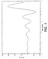
- FIGURE 1 shows the profile of the typical pulse
- FIGURE 2 shows the frequency response caused by the pulse of FIGURE 1 when applied to an MR imaging apparatus.
- the z magnetization is normalized to be 1 at equilibrium.
- Table 1 below lists the frequency characteristics resulting from the application of these pulses.
- shaped pulses lasting for 5 msec were synthesized to desired frequency requirements using N (column 1) hard pulses. From Table 1, it can be appreciated that as N becomes larger and the individual flip angles become smaller, the approximation becomes even more accurate.
- the present inventor has shown that if one converts a shaped pulse into an N+1 hard pulse sequence, with N sufficiently large so that each flip angle of the hard pulse sequence is small, then a N , or the coefficient e -i ⁇ T in the Fourier expansion of ⁇ ( ⁇ ) is proportional to the power (Equation 15). Therefore, in the design of a hard pulse sequence in accordance with the present invention, one specifies ⁇ ( ⁇ ) so that it is close to the desired frequency response, subject to the constraint that log(a N ) or 1-a N is less than ( ⁇ 2 T*E)/2N, where E is the maximum total energy to be allowed for the pulse.
- an appropriate ⁇ ( ⁇ ) can be synthesized, and a hard pulse sequence constructed which can be used as the basis for a shaped (soft) pulse.
- the shaped pulse will have the designated maximum total energy and, as will be described more fully below, a reduced peak power.
- the relationship between the Fourier transform of the frequency response of the pulse and the total energy of the pulse is encoded in the lowest Fourier coefficients of the frequency response.
- the total energy of the shaped pulse is encoded in one of the Fourier coefficients of ⁇ ( ⁇ ).
- the frequency response in order to synthesize the RF pulse with the desired frequency response, one has to specify the frequency response as a finite Fourier series. Typically, one specifies either M z ( ⁇ ), or equivalently
- 2 . One then constructs ⁇ ( ⁇ ) and ⁇ ( ⁇ ) using a phase retrieval algorithm and then constructs the desired pulse. Because algorithms, using the cepstral transform, exist for rapidly obtaining the minimum and maximum phase solutions, such techniques may be readily used for calculating ⁇ ( ⁇ ) as well as ⁇ ( ⁇ ). This approach has the additional advantage that if one specified a symmetric M z ( ⁇ )M z (- ⁇ ) M z ( ⁇ ), one gets a constant phase pulse.
- the basis for reducing the peak power of the pulse is the idea that using variable phase pulses may require less peak power than constant phase pulses because each frequency can be excited by a radio frequency pulse close to it.
- the pulse synthesis algorithm of U.S. Patent No. 5,153,515 is thus modified by constructing a filter for M z ( ⁇ ), or equivalently, for
- the minimum phase solution for ⁇ ( ⁇ ) is then determined so that the total energy of the pulse is unchanged.
- ⁇ ( ⁇ ) is synthesized which is compatible. If ⁇ ( ⁇ ) is chosen such that it is not symmetric in ⁇ , the pulse synthesized will be a variable phase pulse. Since the maximum power requirements of a variable phase pulse are generally less than that of a constant phase pulse (because it can effect a frequency sweep), the peak power may be minimized by choosing a ⁇ ( ⁇ ) which best approximates a frequency sweep. This is accomplished by appropriately selecting the roots for ⁇ ( ⁇ ).
- a phase retrieval algorithm may be used to solve for the roots of
- These roots generally come in pairs (z, 1/z*). As described in that patent, each pair is ordered so that
- M z ( ⁇ ) M z (- ⁇ )
- z* a constant phase pulse
- ⁇ ( ⁇ ) the conjugate
- ⁇ ( ⁇ ) the conjugate
- ⁇ ( ⁇ ) the conjugate
- ⁇ ( ⁇ ) the conjugate
- ⁇ ( ⁇ ) with real coefficients in the expansion and a constant phase pulse.
- the cepstral deconvolution algorithm yields such constant phase pulses.
- a different root selection scheme for ⁇ ( ⁇ ) is chosen. For each ordered pair, z is selected as the solution for ⁇ ( ⁇ ) when the imaginary component of z is greater than or equal to 0; otherwise 1/z* is chosen.
- z may be selected as a solution for ⁇ ( ⁇ ) when the imaginary component of z is less than or equal to 0; otherwise 1/z* is selected.
- Such selections of the roots of ⁇ ( ⁇ ) lead to pulses with variable phase. Because the same ⁇ ( ⁇ ) is used, roughly the same total energy is used. Also, the larger the number of pulses used, the less change there is in the total energy.
- the modified algorithm described herein has been applied to the synthesis of reduced power inversion and excitation pulses.
- the B 1 amplitude (in Hz) for a constant phase pulse is reduced by the use of a reduced power, variable phase pulse in accordance with the invention.
- the peak of B 1 is reduced from 2301 Hz for a constant phase inversion pulse to 1374 Hz for a reduced power, variable phase pulse.
- FIGURE 4 illustrates the phase of the variable phase pulse of FIGURE 3, where peak B 1 is reduced by 40% and the total energy by 64%.
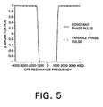
- FIGURE 5 illustrates a comparison of the inversion profiles of the resulting z magnetizations. As illustrated, the two curves are superimposable since they are substantially identical.
- the frequency response of every soft pulse can be uniformly approximated on every bounded frequency range by hard pulse sequences.
- the jth pulse of an N hard sequence lasting for time T can be constructed.
- the soft pulse would have N segments, each lasting for a time T/(N-1). During each segment, one applies a constant B 1 field which has the effect of rotating the 0 frequency spins the same amount as the hard pulses did.
- the frequency responses of the hard pulse sequence and the soft pulse, over a limited frequency range are similar.
- the soft pulse with a similar frequency response to a hard pulse sequence may be formed from a hard pulse sequence by choosing a large number of pulses N for the hard pulse sequence and then choosing a hard pulse sequence which has relatively small flip angles.
- the roots of 1-M z 2 are then chosen in accordance with the techniques described in U.S. Patent No. 5,153,515.
- the root selection for M xy is also made.
- Equation 17 E lim S ⁇ 0 a( S ) ⁇ 2
- the pulse can be defined to be the limit of the pulse lasting from -T to T, as T approaches infinity.
- the power of the pulse is the limit of the power of the finite duration pulses. Therefore, given the frequency response of the pulse, the power is encoded in the value of the Fourier transform of ⁇ ( ⁇ ) at a particular point.
Landscapes
- Physics & Mathematics (AREA)
- High Energy & Nuclear Physics (AREA)
- Condensed Matter Physics & Semiconductors (AREA)
- General Physics & Mathematics (AREA)
- Magnetic Resonance Imaging Apparatus (AREA)
- Control Of Stepping Motors (AREA)
- Regulation And Control Of Combustion (AREA)
Abstract
Description
- The present invention relates to novel methods of selectively exciting specified frequencies of magnetic resonance imaging systems. More specifically, the present invention relates to methods of synthesizing reduced power frequency selective radio frequency (RF) pulse sequences which generate desired frequency dependent excitations when applied to subjects in nuclear magnetic resonance (NMR) imaging systems yet do not exceed the peak power and total energy limitations on the input RF pulses.
- In magnetic resonance and optical spectroscopy, it is necessary to design pulses which will selectively excite only a part of the spectrum. There are several techniques for such selective excitation, including the technique described by the present inventor in U.S. Patent No. 5,153,515.
- In that patent, the present inventor disclosed a method of constructing selective excitations such as π/2, π and refocusing pulse sequences for perturbing the spins of a magnetic resonance imaging system. In particular, the present inventor illustrated that the desired z magnetization, Mz, for a system starting at equilibrium (Mz(ω)=1), can be written as an (N-1)th order Fourier series ωt, where ω is the off-resonance frequency. In addition, if all pulses have the same phase, then the z magnetization is symmetric in frequency (Mz(ω) = Mz(-ω)), and can be written as an Nth order Fourier cosine series in ωt. Then, the present inventor illustrated that, given a Fourier series or Fourier cosine series (in ωt) representing the desired z magnetization, it is possible to perform an inversion of the nonlinear problem to determine a hard pulse sequence which will actually yield the desired response. The desired z magnetization was written as a Fourier series in ωt using finite impulse response filter theory so that hard pulse sequences could be generated which would yield an optimal frequency response when applied to the system. It was also illustrated that a soft pulse could be generated from the hard pulse sequence which would yield the same frequency response as the hard pulse sequence.
- In the direct synthesis approach described in U.S. Patent No. 5,153,515, one specifies the desired frequency spectrum and then synthesizes an RF pulse which will yield that desired response. Unfortunately, one has little control over the shape of the RF pulse which is actually applied to the system. However, in practice, it is necessary to limit the pulse shape. For example, the peak power (instantaneous power) of the applied pulse is limited by the transmitter power. Also, the total energy used by the pulse (i.e., the integral of the instantaneous power over the pulse duration) is limited by concerns for sample or tissue heating. In practice, the total energy deposited by the RF pulse is related to the specific absorption rate (SAR), which is limited by FDA guidelines. This limitation poses severe constraints on some fast imaging schemes. As a result, it is desired to develop a technique for the synthesis of reduced power pulses with a specified frequency profile within FDA guidelines yet which also may be used to generate the desired frequency response characteristics.
- As noted in U.S. Patent No. 5,153,515, the relationship between a radio frequency pulse and the frequency response of its effects on even a simple spin system is complex and nonlinear. The nonlinearity of this relationship has led to difficulties in the analysis and inversion of this relationship. However, over the last several years, many of these difficulties have been overcome. For example, given a desired frequency profile, the present inventor has proposed in U.S. Patent No. 5,153,515 an algorithm which allows for the generation of pulses that will yield the desired response. Other systems for generating a desired frequency profile have also been proposed by Pauly et al. in an article entitled "Parameter Relations for the Shinnar-Le Roux Selective Excitation Pulse Design Algorithm," IEEE Trans. Med. Imag., Vol. 10, No. 1, pp. 53-65 (1991); Carlson in an article entitled "Exact Solutions for Selective-Excitation Pulses," J. Magn. Reson., Vol. 94, pp. 376-386 (1991); and Yagle in an article entitled "Inversion of the Bloch Transform in Magnetic Resonance Imaging Using Asymmetric Two-Component Inverse Scattering," Inverse Problems, Vol. 6, pp. 133-151 (1990). However, such algorithms offer only a partial solution in that there is still no illustration of the relationship between the details of the pulse shape and the frequency response. For example, if the pulse is restricted so that either the total energy or the peak power is bounded by a preset maximum, the limits this places on the possible frequency response have heretofore been unknown. Furthermore, outside of using a search algorithm such as that described by Conolly et al. in an article entitled "Optimal Control Solutions to the Magnetic Resonance Selective Excitation Problem," IEEE Trans. Med. Imaging, Vol. 5, No. 2, pp. 106-115 (1986), there is no known algorithm for incorporating constraints on the energy into the direct synthesis algorithms.
- Recently, the present inventor obtained a partial solution to the relationship between a pulse and its frequency response. In particular, it was illustrated by Shinnar et al. in an article entitled "Inversion of the Bloch Equation," J. Chem. Phys., Vol. 98, pp. 6121-6128 (1993), that if pulses are restricted to be of finite time duration T, then the Fourier transform of the frequency response function is nonzero only over a finite period in the time domain. In other words, if the z magnetization, as a function of frequency ω, is Fourier transformed back into the time domain s, it is zero for all |s| > T. Similar results have been obtained for all other functions which can be used to describe the frequency response. The present inventor further showed that one could not have a frequency response that had a sharper transition zone between excited and unexcited frequencies than the Fourier transform limit, 1/T. This solved the open problem about the limits achievable by RF pulses described by McDonald et al. in an article entitled "Testing the Limits of Shape Optimization by Large-Flip-Angle Pulses," J. Magn. Reson., Vol. 99, pp. 282-291 (1992).
- Thus, if pulses are restricted to a finite time duration T, the Fourier transform of the frequency response of the RF pulse completely characterizes the space of magnetizations reachable with a finite duration RF pulse. In other words, not only must any magnetization profile achievable by a finite duration RF pulse satisfy this constraint, but also, for any magnetization function which satisfies this constraint, a finite duration pulse can be synthesized which yields the desired magnetization.
- In practice, many other limitations on the pulse shape are useful. For example, the total energy and peak power used by a pulse are clearly of major significance because of sample heating and hardware limitations. As noted above, in clinical imaging, specific absorption rate (SAR) significantly limits some fast imaging schemes. Unfortunately, to date, there exists no theory or method known to the inventor for directly relating the energy of a pulse to the frequency response function. At present, one has to invert the Bloch equation and then calculate the energy. To the inventor's knowledge, no one has suggested calculating the energy requirement directly from the frequency response function.
- It is thus desired to develop a technique which relates the energy requirement to the frequency response function so that the peak power of the synthesized "optimal" RF pulses can be reduced without any change in the excitation profile, time of the pulse, or the total energy of the pulse. Also, it is desired to develop a technique in which the total energy of the pulse is reduced as well. The method of the present invention has been developed for these purposes.
- In the above-mentioned paper by John Pauly et al. ("Parameter Relations for the Shinnar-Le Roux Selective Excitation Pulse Design Algorithm", IEEE Trans. Med. Im., Vol. 10, pages 53 to 65, 1991), there is described a method of performing magnetic resonance imaging comprising the method steps forming the preamble of claim 1.
- The above-mentioned needs in the prior art have been met by the present invention as a result of the present inventor's discovery of how the power requirements of the RF pulse are encoded in the frequency response of the RF pulse. As a result of this discovery, one merely needs to specify in the synthesis algorithm described in U.S. Patent No. 5,153,515 the total amount of power so that a pulse can be synthesized with the desired power.
- The present inventor has discovered that the total energy of the pulse is encoded in the lowest order Fourier coefficients of the frequency response and that this knowledge can be used in inverting the Bloch equation to yield selective RF pulses with reduced total energy. Reductions in total energy on the order of 10-20% have already been achieved using the techniques of the invention. In addition, modifications to the techniques disclosed in U.S Patent No. 5,135,515 have led to reductions in peak power on the order of 60-70% without changing the frequency response.
- Thus, in accordance with the present invention there is provided a method of generating a desired physically realizable, frequency dependent excitation of a system having predetermined constraints on its frequency response, as defined in claim 1.
- In a preferred embodiment of the invention, a method of generating a desired physically realizable, frequency dependent excitation of a system having predetermined constraints on its frequency response is described.
- In the preferred embodiment, the system is a nuclear magnetic resonance imaging system and the hard pulse sequence of N pulses is used to form an imaging slice for display. In NMR, the desired frequency dependent excitation is a magnetization applied to the system when the system is in an external B0 magnetic field, and the desired frequency dependent excitation includes a rotation operator applied to perturb the system. The synthesized hard pulse sequence of N pulses is then used to refocus the imaging slice for display.
- Typically, the predetermined constraints on the frequency response of the system include a maximum acceptable total energy and a reduction in maximum peak power of the hard pulse sequence. To accommodate such constraints, the synthesizing step (c) comprises the step of determining the constraints on the pulse profile of the approximation which yield the desired frequency dependent excitation yet satisfy the predetermined constraints on the input pulses to the system.
- In the preferred embodiment, step (a) comprises the step of determining, as a function of frequency ω, an approximation to a desired physically realizable magnetization Mz in a direction z parallel to an external magnetic field B for the desired frequency dependent excitation of the system. Preferably, the desired frequency dependent excitation is described by a spinor of the form (α(ω),β(ω)), where Mz(ω) = |α(ω)|2 - |β(ω)|2, whereand where
 a and b being coefficients of the hard pulse sequence and T being a time duration of the hard pulse sequence.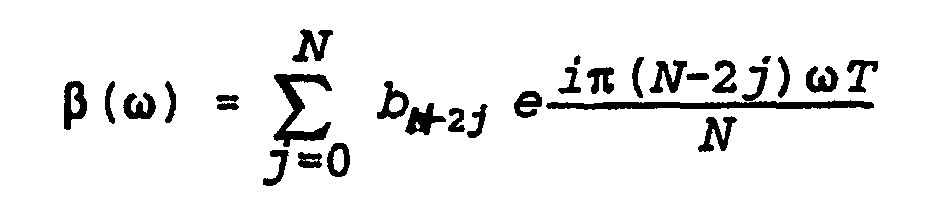
- The present inventor has discovered that the total energyfor the hard pulse sequence applied to the system is proportional to a Fourier coefficient for α, where the Fourier coefficient is defined as:

- On the other hand, the peak power may be reduced during synthesizing step (c) by solving for the roots of β(ω)2, where |β(ω)|2 = 1 - |α(ω)|2 = (1 - Mz(ω))/2, placing the roots of |β(ω)|2 in ordered pairs (z, 1/z*), where |z|>=1, and then either selecting z as a solution for β(ω) when zimaginary>=0, selecting 1/z* as a solution for β(ω) when zimaginary<0, selecting z as a solution for β(ω) when the zimaginary=<0, or selecting 1/z* as a solution for β(ω) when zimaginary>0. This approach leads to RF pulses with variable phase but less peak power. Since this calculation is independent of the determination of α(ω), the same total energy results.
- Of course, the technique of the invention is preferably used to generate "optimal" reduced power soft pulses. In such a case, the soft pulse is synthesized from the hard pulse sequence using the technique described in U.S. Patent No. 5,153,515 so that the frequency dependent excitation of the system substantially corresponds to the frequency dependent excitation of the system when the hard pulse sequence is applied.
- The above and other objects and advantages of the invention will become more apparent to one skilled in the art in view of the accompanying drawings, of which:
- FIGURE 1 illustrates a typical RF pulse synthesized in accordance with the invention.
- FIGURE 2 illustrates the frequency response of the RF pulse of FIGURE 1 where the z magnetization is normalized to be one at equilibrium.
- FIGURE 3 illustrates the amplitude of a constant phase inversion pulse and of a reduced power, variable phase pulse produced in accordance with the invention. As illustrated, the energy B1 of the variable phase pulse is reduced by 40% and the peak power by 64% compared to the constant phase pulse.
- FIGURE 4 illustrates the phase of the variable phase pulse of FIGURE 3.
- FIGURE 5 illustrates a comparison of the conversion profiles in response to the constant phase pulse and the variable phase pulse. As illustrated, the inversion profiles are substantially identical.
-
- A method in accordance with a presently preferred exemplary embodiment of the invention will be described below with reference to FIGURES 1-5. It will be appreciated by those of ordinary skill in the art that the description given herein with respect to those figures is for exemplary purposes only and is not intended in any way to limit the scope of the invention. All questions regarding the scope of the invention may be resolved by referring to the appended claims.
- In U.S. Patent No. 5,153,515, the present inventor described how to generate a B1 profile which will give the desired excitation profile for NMR imaging and the like. In particular, a technique was described which allows an ideal pulse to be approximated as closely as possible. Tailored hard pulse sequences or soft pulse sequences were designed which excite a narrow bandwidth of resonant frequencies for clarity of imaging for better clinical diagnosis. The techniques described in that patent describe how to generate hard pulse sequences or soft pulses which achieve frequency responses as close as possible to the ideal or optimal pulse.
- In accordance with the method described in U.S. Patent No. 5,153,515, one starts with a physically realizable z magnetization which may be achieved by a hard pulse sequence and then determines a hard pulse sequence which will actually yield that z magnetization. In particular, an N hard pulse sequence to be applied around the x axis within a total duration of T has a magnetization response Mz which is written as a Fourier cosine series in which |Mz(ω)| is always less than or equal to one. Then, if a desired Mz(ω) is given, the equation for calculating Mz(ω) reduces to a phase retrieval or deconvolution problem in which Mz(ω) may be converted to a complex polynomial in s = exp (iωT/(N-1)) and then solved for the roots of the polynomial 1 - Mz 2(ω), or equivalently, for the two polynomials 1 - Mz(ω) and 1 + Mz(ω). One then groups the roots of the polynomials by means of symmetry considerations and chooses half of them. There are also techniques such as cepstral deconvolution which allow for the solution of Mxy(ω) as an (N-1) degree polynomial in s. This is a representation of Mxy(ω) as an (N-1)th degree complex Fourier series. As will be noted in more detail below, by representing these magnetization vectors as spinors and selecting different roots for the polynomials, constraints such as peak power and total energy over the pulse may be placed on the input pulses used to generate the desired frequency dependent excitation.
- The next step in the process is to find a pulse sequence which will yield the Fourier series which will provide the desired magnetization. Generally, Mz is a complex Fourier series. As noted in U.S. Patent No. 5,153,515, the resulting problem is similar to a problem in digital filter design, namely, the design of finite impulse response filters. Using finite impulse response filter theory, a desired hard pulse sequence may be created by specifying the desired z magnetization, the number of pulses, and the duration of the pulse sequence. One then views Mz as a Fourier series in ωT/(N-1) and uses a finite impulse response filter design technique to obtain a Fourier series which specifies Mz as having certain desired values over certain specified ranges. One then normalizes the Fourier series obtained for Mz so that it is always less than or equal to one in absolute value and then one uses the techniques described in U.S. Patent No. 5,153,515 to synthesize the consistent Mxy and a pulse sequence to actually generate that magnetization, B1.
- The present invention is an extension of the technique described in U.S. Patent No. 5,153,515 in that now one may specify further constraints on the input pulses such as the maximum total energy over the pulse duration and/or that the peak power should be reduced. To explain how this may be accomplished in accordance with the present invention, the magnetization system will be described using the spinor formulation of the Bloch equation without relaxation. In this version of the formulation, a classical description of nuclear magnetic resonance is used in which the effect of being off resonance or of a radio frequency pulse is to induce a rotation.
- A counterclockwise rotation of radians around an axis having directional cosines (cx, cy, cz) can be written as the following complex unitary matrix:
- The effect of a radio frequency pulse on a spin at frequency ω can be described by a spinor [α(ω), β(ω)]. When applied to a system at equilibrium (Mz = 1), then the resultant magnetization can be written as:
- As noted in U.S. Patent No. 5,153,515, each hard pulse can be considered to be a rotation around an axis in the xy plane, lasting for an infinitesimal time. The sequence consists of (N+1) hard pulses, separated by time T/N, when the system precesses freely around the z axis. The total duration of the sequence is T. It was also shown that the spinor corresponding to such a pulse sequence can be written as:
 Using such notation, the spinor corresponding to a rotation by angle around an axis in the xy plane with phase is [cos(/2), eisin(/2)].
- Over any bounded frequency range, the frequency response of any shaped pulse can be approximated to arbitrary accuracy by an N hard pulse sequence, for large N. Furthermore, the flip angles and phases of the hard pulses may be derived from the shaped pulse amplitude. In other words, if the shaped pulse is described by ω1(t), where ω1(t) is in radians, then the jth hard pulse has amplitude
- The present inventor has discovered that the total energy of the shaped pulse is encoded in one of the Fourier coefficients of α(ω). If the total energy E of the shaped pulse lasting from time 0 to time T is defined as:where |ω1(t)| is the amplitude (in Hz) of the radio frequency pulse, then using the notation of Equation 4, it can be shown that:
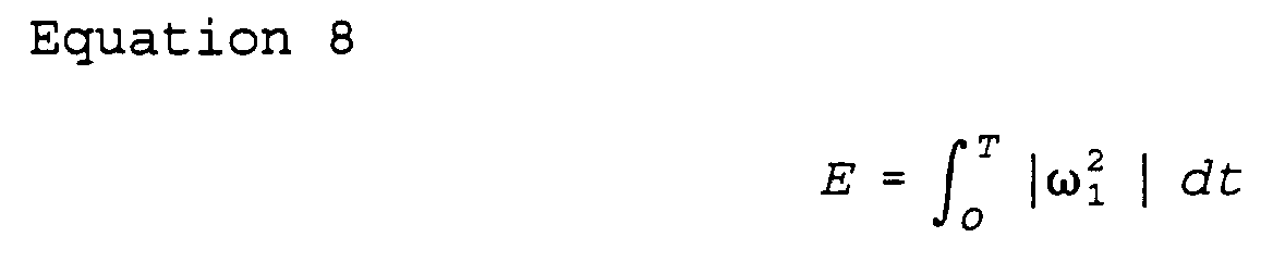
- The proof of this is relatively simple. In the hard pulse sequence:For large N, a hard pulse sequence derived from a shaped pulse sequence has a small j which can be written as (O (1/N)) using Landau's O notation. As a result,
 Since the last term can be neglected, substituting for , we get:
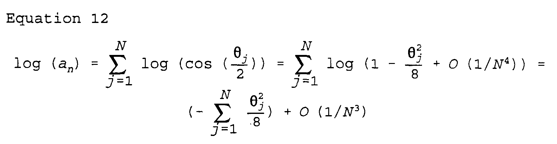 However, using a Riemann sum approximation for the integral defining the energy E, we get:
 Therefore:
- The relationship of Equation 15 has a number of immediate consequences. First, it establishes that the total pulse energy is proportional to the Fourier coefficient, a, and that everything else relates to the shape of the pulse's profile. Second, for a hard pulse sequence derived from a shaped pulse, it establishes that 1 - aN is O(1/N). This can serve as a rough check to see if N is large enough, which also implies that the proportionality is valid for large N. Third, if α(ω) is specified, the total energy has also been specified. Therefore, all the RF pulses which can be generated with the same α(ω) but different β(ω) will have the same energy.
- In accordance with the invention, if only Mz(ω) is specified, then one has only specified |α(ω)|2. Generally, α(ω) is generated using a phase retrieval algorithm. Given a desired frequency response, it is known that one should choose the minimum phase solution for α(ω) corresponding to all roots outside the unit circle in order to obtain the pulse with the least energy. For example, Pauly et al. teach in the afore-mentioned article entitled "Parameter Relations for the Shinnar-Le Roux Selective Excitation Pulse Design Algorithm", IEEE Trans. Med. Imaging, Vol. 10, No. 1, March 1991, that the minimum phase solution minimizes the power requirements. However, Pauly et al. do not illustrate that the frequency response could be modified by choosing a different α(ω). In other words, given α(ω) with the same |α(ω)|2, Pauly et al. demonstrated that the minimum phase α(ω) was the minimum energy. However, the comparison of two different α(ω) was not made by Pauly et al., and Pauly et al. did not suggest that such a consideration should be introduced into the pulse design protocol.
- If Mz(ω) is symmetric (i.e., Mz(ω) = Mz(-ω), then the minimum phase solution has all real coefficients. Therefore, a pulse with constant RF phase can be synthesized which has minimum energy. In other words, for symmetric |α(ω)|2, one cannot reduce the energy requirements by using variable phase pulses. However, for this relationship to be valid, it is necessary that N be sufficiently large that approximations for the cosine of the flip angle are valid.
- To illustrate this, a series of pulses have been synthesized with different frequency responses. The energy of these pulses vary by a factor of almost 40. FIGURE 1 shows the profile of the typical pulse, and FIGURE 2 shows the frequency response caused by the pulse of FIGURE 1 when applied to an MR imaging apparatus. In FIGURE 2, the z magnetization is normalized to be 1 at equilibrium. Table 1 below lists the frequency characteristics resulting from the application of these pulses. In Table 1, shaped pulses lasting for 5 msec were synthesized to desired frequency requirements using N (column 1) hard pulses. From Table 1, it can be appreciated that as N becomes larger and the individual flip angles become smaller, the approximation becomes even more accurate.
NUMBER OF PULSES EXCITATION ANGLE WIDTH (± HZ) ENERGY (FROM PULSE) ENERGY (FROM EQUATION 15) % ERROR 40 90 500 96.1462 96.3247 .186 40 90 1000 165.537 166.572 .625 40 90 2000 301.328 307.025 1.891 80 90 500 96.3913 96.4867 .099 80 90 1000 166.401 166.725 .195 80 90 2000 305.921 307.148 .401 80 180 500 988.438 999.140 1.083 80 180 1000 1822.55 1866.4 2.406 80 180 2000 3377.18 3636.91 7.691 120 180 2000 3515.5 3622.96 3.057 - In summary, the present inventor has shown that if one converts a shaped pulse into an N+1 hard pulse sequence, with N sufficiently large so that each flip angle of the hard pulse sequence is small, then aN, or the coefficient e-iπωT in the Fourier expansion of α(ω) is proportional to the power (Equation 15). Therefore, in the design of a hard pulse sequence in accordance with the present invention, one specifies α(ω) so that it is close to the desired frequency response, subject to the constraint that log(aN) or 1-aN is less than (π2T*E)/2N, where E is the maximum total energy to be allowed for the pulse. Given such an α(ω), an appropriate β(ω) can be synthesized, and a hard pulse sequence constructed which can be used as the basis for a shaped (soft) pulse. However, in accordance with the invention, the shaped pulse will have the designated maximum total energy and, as will be described more fully below, a reduced peak power.
- Thus, the relationship between the Fourier transform of the frequency response of the pulse and the total energy of the pulse is encoded in the lowest Fourier coefficients of the frequency response. In particular, the total energy of the shaped pulse is encoded in one of the Fourier coefficients of α(ω). This observation allows the pulse synthesis algorithm described in U.S. Patent No. 5,153,515 to use the total energy of the pulse as a design parameter, further elucidating the complex relationship between an RF pulse and its frequency response. In other words, the problem of synthesizing reduced energy pulses is reduced to the problem of synthesizing a Fourier series whose frequency profile is close to a desired profile, subject to a constraint on one Fourier coefficient. Using the technique of the invention, reductions in energy of inversion pulses of the order of 10-20% have been achieved with minimal effects on the inversion profile. Further reductions are achievable with proportionately more effect on the inversion profile. For many rapid imaging schemes, this reduction in SAR per pulse can be highly significant. Reduction of Peak Power
- The above approach illustrates how to reduce the total energy required by the pulse. However, because of transmitter power limitations, it is often desirable to reduce the maximum power required by the RF pulse as well. The following description illustrates how this may be done.
- As noted above, in order to synthesize the RF pulse with the desired frequency response, one has to specify the frequency response as a finite Fourier series. Typically, one specifies either Mz(ω), or equivalently |α(ω)|2 or |β(ω)|2. One then constructs α(ω) and β(ω) using a phase retrieval algorithm and then constructs the desired pulse. Because algorithms, using the cepstral transform, exist for rapidly obtaining the minimum and maximum phase solutions, such techniques may be readily used for calculating β(ω) as well as α(ω). This approach has the additional advantage that if one specified a symmetric Mz(ω)Mz(-ω) = Mz(ω), one gets a constant phase pulse.
- In accordance with the method of the invention, on the other hand, the basis for reducing the peak power of the pulse is the idea that using variable phase pulses may require less peak power than constant phase pulses because each frequency can be excited by a radio frequency pulse close to it. The pulse synthesis algorithm of U.S. Patent No. 5,153,515 is thus modified by constructing a filter for Mz(ω), or equivalently, for |α(ω)|2. The minimum phase solution for α(ω) is then determined so that the total energy of the pulse is unchanged.
- Where the present method differs is in the choice of β(ω). In accordance with the method of the invention, if an α(ω) is specified which automatically specifies the total energy, then a β(ω) is synthesized which is compatible. If β(ω) is chosen such that it is not symmetric in ω, the pulse synthesized will be a variable phase pulse. Since the maximum power requirements of a variable phase pulse are generally less than that of a constant phase pulse (because it can effect a frequency sweep), the peak power may be minimized by choosing a β(ω) which best approximates a frequency sweep. This is accomplished by appropriately selecting the roots for β(ω).
- As noted in the U.S. Patent No. 5,153,515, a phase retrieval algorithm may be used to solve for the roots of |β(ω)|2. These roots generally come in pairs (z, 1/z*). As described in that patent, each pair is ordered so that |z| ≥ 1. For each pair, one chooses one element of the pair, zj, and:where c is a suitable normalizing constant. The result is a solution for β(ω).
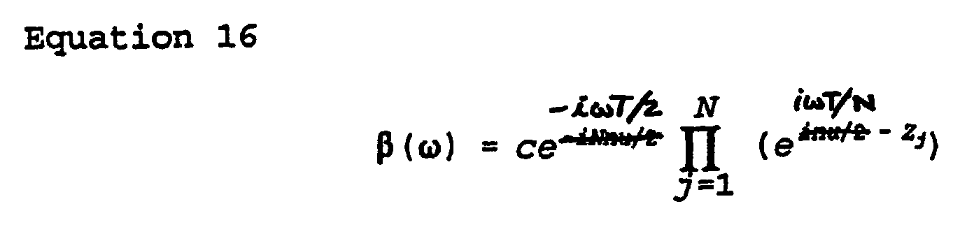
- If Mz(ω) is symmetric (i.e., Mz(ω) = Mz(-ω)), then if z is a root, so is z*. To obtain a constant phase pulse, whenever a root is chosen, its conjugate is also chosen. This will lead to a β(ω) with real coefficients in the expansion and a constant phase pulse. The cepstral deconvolution algorithm yields such constant phase pulses. However, in order to obtain reduced peak power pulses in accordance with the invention, a different root selection scheme for β(ω) is chosen. For each ordered pair, z is selected as the solution for β(ω) when the imaginary component of z is greater than or equal to 0; otherwise 1/z* is chosen. On the other hand, z may be selected as a solution for β(ω) when the imaginary component of z is less than or equal to 0; otherwise 1/z* is selected. Such selections of the roots of β(ω) lead to pulses with variable phase. Because the same α(ω) is used, roughly the same total energy is used. Also, the larger the number of pulses used, the less change there is in the total energy.
- Those skilled in the art will appreciate that unlike the minimum phase solution, the roots are not always outside the unit circle |z|>1. Those skilled in the art will also appreciate that minor modifications to the process may be made where a few roots are chosen by different criteria, sos long as substantially similar results are yielded.
- The modified algorithm described herein has been applied to the synthesis of reduced power inversion and excitation pulses. As shown in FIGURE 3, the B1 amplitude (in Hz) for a constant phase pulse is reduced by the use of a reduced power, variable phase pulse in accordance with the invention. For example, in FIGURE 3, the peak of B1 is reduced from 2301 Hz for a constant phase inversion pulse to 1374 Hz for a reduced power, variable phase pulse. FIGURE 4 illustrates the phase of the variable phase pulse of FIGURE 3, where peak B1 is reduced by 40% and the total energy by 64%. FIGURE 5 illustrates a comparison of the inversion profiles of the resulting z magnetizations. As illustrated, the two curves are superimposable since they are substantially identical.
- Thus, it is possible to reduce the peak power demands of a pulse by properly selecting the roots for β(ω), without any effect on the excitation or inversion profile, time of the pulse, or the total energy of the pulse sequence. Indeed, numerous constraints on the desired frequency response for the Fourier transform in such a response may be introduced in accordance with the invention in order to, for example, minimize the total energy of the pulse or to provide reduced peak powers. Peak power reductions on the order of 60-70% have been obtained using the techniques of the present invention.
- As noted in U.S. Patent No. 5,153,515, the frequency response of every soft pulse can be uniformly approximated on every bounded frequency range by hard pulse sequences. In other words, given a soft pulse lasting for time T, for a given N, the jth pulse of an N hard sequence lasting for time T can be constructed. As described therein, one can reverse the procedure by constructing the soft pulse from a given hard pulse sequence. That is, given an N hard pulse sequence lasting for time T, one can construct a soft pulse lasting for T*(N/(N-1)). The soft pulse would have N segments, each lasting for a time T/(N-1). During each segment, one applies a constant B1 field which has the effect of rotating the 0 frequency spins the same amount as the hard pulses did.
- If the flip angles of the hard pulses are relatively small, the frequency responses of the hard pulse sequence and the soft pulse, over a limited frequency range, are similar. As described in U.S. Patent No. 5,153,515, the soft pulse with a similar frequency response to a hard pulse sequence may be formed from a hard pulse sequence by choosing a large number of pulses N for the hard pulse sequence and then choosing a hard pulse sequence which has relatively small flip angles. The roots of 1-Mz 2 are then chosen in accordance with the techniques described in U.S. Patent No. 5,153,515. The root selection for Mxy is also made.
- In accordance with the invention, a reduced power soft pulse is generated by defining the spinor components of a pulse, α(ω) and β(ω), and assuming that the pulse lasts for time T. Then, for a soft pulse, it can be shown that the Fourier transform of the eπiωTα(ω) = g (s) is 0 for s (the Fourier transform variable) as s approaches 0. In other words, the limit as s approaches 0 for g(s) is equal to E*π2, where E is the total energy of the soft pulse. Also, a(s) is zero for s<0 or s>T. Thus:
- Certain embodiments of the invention have been described in detail above which will provide methods of pulse generation for optimally exciting specified frequency bands with certain constraints on the input pulse. While preferred embodiments have been shown and described, modifications will be recognized by those with ordinary skill in the art. For example, the invention need not be implemented using spinors but may be represented using conventional nomenclature. Accordingly, all such modifications are intended to be included within the scope of the invention as defined by the following claims.
Claims (12)
- A method of generating a desired physically realizable, frequency dependent excitation of a system comprising the steps of:characterized in that said method has predetermined constraints on its frequency response and further comprises the step of:(a) determining, as a function of frequency, an approximation to the desired frequency dependent excitation;(b) synthesizing a hard pulse sequence of N pulses which generates said approximation; and either:(A) (c) applying the hard pulse sequence of N pulses synthesized in step (b) to said system; or(B) (d) synthesizing from said hard pulse sequence of N pulses a soft pulse which causes a frequency dependent excitation of said system substantially corresponding to the frequency dependent excitation of said system when said hard pulse sequence of N pulses is applied and applying the soft pulse so synthesized to said system;and in that each of said hard pulse sequence satisfies said predetermined constraints on the input pulses.(e) specifying said predetermined constraints on input pulses to the system which will yield the desired frequency dependent excitation, said predetermined constraints on the frequency response of said system including at least one of a maximum acceptable total energy for each of said input pulses and a reduction in maximum peak power of each of said input pulses which will still yield the desired frequency dependent excitation;
- A method as claimed in claim 1, wherein said system is a nuclear magnetic resonance imaging system and either (a) said hard pulse sequence of N pulses or(B) said soft pulse is used to form an imaging slice for display.
- A method as claimed in claim 2, wherein said desired frequency dependent excitation is a magnetization applied to said system when said system is in an external magnetic field.
- A method as claimed in claim 3, wherein said desired frequency excitation includes a rotation operator applied to said system when said system is in said external magnetic field and either (A) the synthesized hard pulse sequence of N pules or (B) the synthesized soft pulse is used to refocus said imaging slice for display.
- A method as in claim 1, wherein said synthesizing step (c) comprises the step of determining constraints of a pulse profile of said approximation which yield said desired frequency dependent excitation yet satisfy said predetermined constraints on the input pulses to said system.
- A method as in claim 1, wherein said determining step (a) comprises the step of determining, as a function of frequency ω, an approximation to a desired physically realizable magnetization Mz in a direction z parallel to an external magnetic field B for the desired frequency dependent excitation of said system.
- A method as in claim 1, wherein said desired frequency dependent excitation is described by a spinor of the form (α(ω),β(ω)), where Mz(ω) = |α(ω)|2 - |β(ω)|2, and whereand where
 where a and b are coefficients of said hard pulse sequence of N pulses and T is a time duration of said hard pulse sequence of N pulses.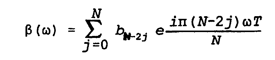
- A method as claimed in claim 1, wherein:(a) said hard pulse sequence has a predetermined maximum total energy during a duration T of said hard pulse sequence and said hard pulse sequence has a peak power which is reduced from the peak power which results when a minimum phase solution to a determination of the roots of β(ω) is used in calculation of a desired frequency dependent magnetization Mz;(b) the step of determining comprises determining, as a function of frequency ω, an approximation to the desired frequency dependent magnetization Mz in a direction z parallel to an external magnetic field B for the desired frequency dependent excitation of said system, where |Mz|2 = |α|2 - |β|2;(c) the step of specifying predetermined constraints comprises the step of selecting roots for α which minimize the total energy of said hard pulse sequence during said duration T and roots for β which minimize the peak power of each pulse of said hard pulse sequence during said duration T; and(d) the step of synthesizing comprises synthesizing the hard pulse sequence of N pulses which generates the approximation for Mz having the roots for α and β in the selecting step.
- A method as claimed in claims 7 or claim 8, wherein the maximum acceptable total energyfor said hard pulse sequence of N pulses applied to said system is proportional to a Fourier coefficient for ·, where said Fourier coefficient is defined as:

- A method as claimed in claim 9, wherein said synthesizing step (c) comprises the step of synthesizing α(ω) using a minimum phase solution so that it approximates the desired frequency dependent excitation, said step of synthesizing α(ω) being subject to the constraint that 1 - aN < (π2T*E) / 2N, where E is the maximum acceptable total energy allowed for said hard pulse sequence of N pulses.
- A method as claimed in claim 1, wherein(a) said hard pulse sequence has a predetermined maximum total energy during a duration T of said hard pulse sequence and said hard pulse sequence has a peak power which is reduced from the peak power which results when a minimum phase solution to a determination of the roots of β(ω) is used in calculation of a desired frequency dependent magnetization Mz;(b) the step of determining comprises determining, as a function of frequency ω, an approximation to the desired frequency dependent magnetization Mz in a direction z parallel to an external magnetic field B for the desired frequency dependent excitation of said system;(c) the step of specifying predetermined constraints comprises the step of specifying said predetermined maximum total energy and a desired reduction in peak power for the desired frequency dependent excitation;(d) the step of synthesizing comprises synthesizing from Mz (ω), said predetermined maximum total energy, and the desired reduction in peak power the hard pulse sequence of N pulses which generates the approximation for Mz determined in step (b), said hard pulse sequence having a total energy no greater than said predetermined maximum total energy and each pulse of said pulse sequence having a peak power reduced from the peak power which results when the minimum phase pulse solution to the determination of the roots of β(ω) is used in calculation of the desired frequency dependent magnetization Mz.
- A method as claimed in claim 10 or claim 11, wherein said synthesizing step (c) comprises the step of solving for the roots of β(ω)2, where |β(ω)|2 = 1 - |α(ω)|2 = (1 - Mz(ω))/2, placing the roots of |β(ω)|2 in ordered pairs (z, 1/z*), where |z|>=1, and then either selecting z as a solution for β(ω) when zimaginary>=0, selecting 1/z* as a solution for β(ω) when zimaginary<0, selecting z as a solution for β(ω) when the zimaginary=<0 or selecting 1/z* as a solution for β(ω) when zimaginary>0.
Applications Claiming Priority (3)
| Application Number | Priority Date | Filing Date | Title |
|---|---|---|---|
| US08/282,220 US5572126A (en) | 1994-07-28 | 1994-07-28 | Reduced power selective excitation RF pulses |
| US282220 | 1994-07-28 | ||
| PCT/US1995/009454 WO1996003665A1 (en) | 1994-07-28 | 1995-07-26 | Reduced power selective excitation rf pulses |
Publications (3)
| Publication Number | Publication Date |
|---|---|
| EP0801748A1 EP0801748A1 (en) | 1997-10-22 |
| EP0801748A4 EP0801748A4 (en) | 1997-12-03 |
| EP0801748B1 true EP0801748B1 (en) | 2004-01-21 |
Family
ID=23080557
Family Applications (1)
| Application Number | Title | Priority Date | Filing Date |
|---|---|---|---|
| EP95927474A Expired - Lifetime EP0801748B1 (en) | 1994-07-28 | 1995-07-26 | Reduced power selective excitation rf pulses |
Country Status (8)
| Country | Link |
|---|---|
| US (1) | US5572126A (en) |
| EP (1) | EP0801748B1 (en) |
| JP (1) | JP3647459B2 (en) |
| AT (1) | ATE258314T1 (en) |
| AU (1) | AU696291B2 (en) |
| CA (1) | CA2196216C (en) |
| DE (1) | DE69532480T2 (en) |
| WO (1) | WO1996003665A1 (en) |
Families Citing this family (15)
| Publication number | Priority date | Publication date | Assignee | Title |
|---|---|---|---|---|
| DE19612217C1 (en) * | 1996-03-27 | 1997-08-07 | Siemens Ag | Pulse sequence for NMR device |
| US6441613B1 (en) * | 1996-09-10 | 2002-08-27 | Ge Medical Systems | Frequency selective pulse |
| US6265875B1 (en) * | 1999-05-17 | 2001-07-24 | General Electric Company | Method and apparatus for efficient MRI tissue differentiation |
| US6426623B1 (en) | 2000-09-27 | 2002-07-30 | Mayo Foundation For Medical Education And Research | MRI RF power monitor |
| US7179450B2 (en) * | 2001-09-20 | 2007-02-20 | Medi-Physics, Inc. | Methods for in vivo evaluation of pulmonary physiology and/or function using NMR signals of polarized Xe |
| DE10221850B4 (en) * | 2002-05-16 | 2007-04-05 | Siemens Ag | A method of designing a selective RF pulse and selective RF pulse |
| AU2003300908A1 (en) * | 2002-12-13 | 2004-07-09 | The Trustees Of The University Of Pennsylvania | Practical pulse synthesis via the discrete inverse scattering transform |
| US7042214B2 (en) * | 2004-04-13 | 2006-05-09 | The Board Of Trustees Of The Leland Stanford Junior University | Non-linear symmetric sweep spectral-spatial RF pulses for MR spectroscopy |
| US7423427B2 (en) * | 2004-05-14 | 2008-09-09 | Massachusetts Institute Of Technology | Arbitrarily accurate composite pulse sequences |
| DE102008015054B3 (en) * | 2008-03-19 | 2010-01-28 | Universitätsklinikum Freiburg | MR method for selective excitation |
| US8063637B2 (en) * | 2009-04-16 | 2011-11-22 | General Electric Company | System and method for phase relaxed RF pulse design |
| EP2572210A1 (en) * | 2010-05-21 | 2013-03-27 | Commissariat à l'Énergie Atomique et aux Énergies Alternatives | Method and apparatus for correcting bl - inhomogeneity in slice - selective mri using composite rf pulses |
| CN103323828B (en) * | 2013-05-29 | 2015-08-19 | 中国科学院电子学研究所 | Ultrahigh resolution Space-borne SAR Imaging disposal route and device |
| US12339336B2 (en) | 2023-07-28 | 2025-06-24 | GE Precision Healthcare LLC | System and method to reduce specific absorption rate in magnetic resonance imaging |
| US12625216B2 (en) | 2024-03-20 | 2026-05-12 | GE Precision Healthcare LLC | Magnetic resonance imaging techniques integrating variable rate selective excitation (VERSE) and flow compensation along slice |
Family Cites Families (3)
| Publication number | Priority date | Publication date | Assignee | Title |
|---|---|---|---|---|
| US4760336A (en) * | 1987-02-27 | 1988-07-26 | Stanford University | Variable rate magnetic resonance selective excitation for reducing rf power and specific absorption rate |
| US5153515A (en) * | 1988-04-01 | 1992-10-06 | Trustees Of The University Of Penna. | Methods of generating pulses for selectively exciting frequencies |
| US5280245A (en) * | 1992-07-27 | 1994-01-18 | Board Of Trustees Of The Leland Stanford Junior Unversity | Magnetic resonance apparatus employing delayed self-refocusing RF excitation |
-
1994
- 1994-07-28 US US08/282,220 patent/US5572126A/en not_active Expired - Lifetime
-
1995
- 1995-07-26 AT AT95927474T patent/ATE258314T1/en not_active IP Right Cessation
- 1995-07-26 EP EP95927474A patent/EP0801748B1/en not_active Expired - Lifetime
- 1995-07-26 DE DE69532480T patent/DE69532480T2/en not_active Expired - Fee Related
- 1995-07-26 WO PCT/US1995/009454 patent/WO1996003665A1/en not_active Ceased
- 1995-07-26 AU AU31497/95A patent/AU696291B2/en not_active Ceased
- 1995-07-26 JP JP50596496A patent/JP3647459B2/en not_active Expired - Lifetime
- 1995-07-26 CA CA002196216A patent/CA2196216C/en not_active Expired - Fee Related
Also Published As
| Publication number | Publication date |
|---|---|
| WO1996003665A1 (en) | 1996-02-08 |
| DE69532480D1 (en) | 2004-02-26 |
| EP0801748A4 (en) | 1997-12-03 |
| JP3647459B2 (en) | 2005-05-11 |
| CA2196216C (en) | 2002-05-07 |
| AU3149795A (en) | 1996-02-22 |
| AU696291B2 (en) | 1998-09-03 |
| ATE258314T1 (en) | 2004-02-15 |
| EP0801748A1 (en) | 1997-10-22 |
| CA2196216A1 (en) | 1996-02-08 |
| US5572126A (en) | 1996-11-05 |
| JPH10503678A (en) | 1998-04-07 |
| DE69532480T2 (en) | 2004-11-25 |
Similar Documents
| Publication | Publication Date | Title |
|---|---|---|
| US5217016A (en) | Method for generating optimal pulses for magnetic resonance imaging using spatial modulation of magnetization | |
| AU696291B2 (en) | Reduced power selective excitation RF pulses | |
| Murdoch et al. | Computer-optimized narrowband pulses for multislice imaging | |
| Pauly et al. | Parameter relations for the Shinnar-Le Roux selective excitation pulse design algorithm (NMR imaging) | |
| Brooker et al. | Selective Fourier transform localization | |
| US4999580A (en) | magnetic resonance imaging and spectroscopy using a single excitation pulse for simultaneous spatial and spectral selectivity | |
| EP0206129B1 (en) | Nmr magnetization inversion by non-linear adiabatic fast passage | |
| US4812760A (en) | Multi-dimensional selective NMR excitation with a single RF pulse | |
| Shinnar et al. | The synthesis of soft pulses with a specified frequency response | |
| US5327088A (en) | Multiplexed echo trains in nuclear magnetic resonance | |
| JP2003052667A (en) | Magnetic resonance imaging system | |
| US5619138A (en) | Method of providing an RF pulse for use in NMR | |
| WO1991002260A1 (en) | Time symmetric pulse to rotate magnetization vectors | |
| US5153515A (en) | Methods of generating pulses for selectively exciting frequencies | |
| JP2005524453A (en) | SAR reduced state free precession MRI acquisition with variable flip angle | |
| EP0649539B1 (en) | Frequency calibration for mri scanner | |
| US8368400B2 (en) | Magnetic resonance selective excitation method of a target distribution of magnetization with complete full integration of bloch equations for RF large angle pulses (LAP)'s that are 15 degrees or greater, without small angle approximation | |
| Goelman et al. | Transverse Hadamard spectroscopic imaging technique | |
| US5126671A (en) | Method for exciting transverse magnetization in nmr pulse experiments | |
| US4940940A (en) | Method of radio-frequency excitation in an NMR experiment | |
| JPS6297544A (en) | Nmr signal receiving method | |
| JPH01113033A (en) | Method for determining nuclear magnetic distribution | |
| US4914392A (en) | Amplitude and frequency/phase modulated pulses to achieve plane rotations of nuclear spin magnetization vectors with inhomogeneous B1 | |
| US6472871B2 (en) | Magnetic resonance spectroscopic imaging with a variable repetition time in conjunction with a variable data acquisition time | |
| WO1999035509A1 (en) | Adiabatic pulse design |
Legal Events
| Date | Code | Title | Description |
|---|---|---|---|
| PUAI | Public reference made under article 153(3) epc to a published international application that has entered the european phase |
Free format text: ORIGINAL CODE: 0009012 |
|
| 17P | Request for examination filed |
Effective date: 19970214 |
|
| AK | Designated contracting states |
Kind code of ref document: A1 Designated state(s): AT BE CH DE DK ES FR GB GR IE IT LI LU MC NL PT SE |
|
| A4 | Supplementary search report drawn up and despatched |
Effective date: 19971015 |
|
| AK | Designated contracting states |
Kind code of ref document: A4 Designated state(s): AT BE CH DE DK ES FR GB GR IE IT LI LU MC NL PT SE |
|
| 17Q | First examination report despatched |
Effective date: 20010918 |
|
| GRAH | Despatch of communication of intention to grant a patent |
Free format text: ORIGINAL CODE: EPIDOS IGRA |
|
| GRAS | Grant fee paid |
Free format text: ORIGINAL CODE: EPIDOSNIGR3 |
|
| GRAA | (expected) grant |
Free format text: ORIGINAL CODE: 0009210 |
|
| AK | Designated contracting states |
Kind code of ref document: B1 Designated state(s): AT BE CH DE DK ES FR GB GR IE IT LI LU MC NL PT SE |
|
| PG25 | Lapsed in a contracting state [announced via postgrant information from national office to epo] |
Ref country code: LI Free format text: LAPSE BECAUSE OF FAILURE TO SUBMIT A TRANSLATION OF THE DESCRIPTION OR TO PAY THE FEE WITHIN THE PRESCRIBED TIME-LIMIT Effective date: 20040121 Ref country code: IT Free format text: LAPSE BECAUSE OF FAILURE TO SUBMIT A TRANSLATION OF THE DESCRIPTION OR TO PAY THE FEE WITHIN THE PRE;WARNING: LAPSES OF ITALIAN PATENTS WITH EFFECTIVE DATE BEFORE 2007 MAY HAVE OCCURRED AT ANY TIME BEFORE 2007. THE CORRECT EFFECTIVE DATE MAY BE DIFFERENT FROM THE ONE RECORDED.SCRIBED TIME-LIMIT Effective date: 20040121 Ref country code: FR Free format text: LAPSE BECAUSE OF FAILURE TO SUBMIT A TRANSLATION OF THE DESCRIPTION OR TO PAY THE FEE WITHIN THE PRESCRIBED TIME-LIMIT Effective date: 20040121 Ref country code: ES Free format text: LAPSE BECAUSE OF FAILURE TO SUBMIT A TRANSLATION OF THE DESCRIPTION OR TO PAY THE FEE WITHIN THE PRESCRIBED TIME-LIMIT Effective date: 20040121 Ref country code: CH Free format text: LAPSE BECAUSE OF FAILURE TO SUBMIT A TRANSLATION OF THE DESCRIPTION OR TO PAY THE FEE WITHIN THE PRESCRIBED TIME-LIMIT Effective date: 20040121 Ref country code: BE Free format text: LAPSE BECAUSE OF FAILURE TO SUBMIT A TRANSLATION OF THE DESCRIPTION OR TO PAY THE FEE WITHIN THE PRESCRIBED TIME-LIMIT Effective date: 20040121 Ref country code: AT Free format text: LAPSE BECAUSE OF FAILURE TO SUBMIT A TRANSLATION OF THE DESCRIPTION OR TO PAY THE FEE WITHIN THE PRESCRIBED TIME-LIMIT Effective date: 20040121 |
|
| REG | Reference to a national code |
Ref country code: GB Ref legal event code: FG4D |
|
| REG | Reference to a national code |
Ref country code: CH Ref legal event code: EP |
|
| REG | Reference to a national code |
Ref country code: IE Ref legal event code: FG4D |
|
| REF | Corresponds to: |
Ref document number: 69532480 Country of ref document: DE Date of ref document: 20040226 Kind code of ref document: P |
|
| PG25 | Lapsed in a contracting state [announced via postgrant information from national office to epo] |
Ref country code: SE Free format text: LAPSE BECAUSE OF FAILURE TO SUBMIT A TRANSLATION OF THE DESCRIPTION OR TO PAY THE FEE WITHIN THE PRESCRIBED TIME-LIMIT Effective date: 20040421 Ref country code: GR Free format text: LAPSE BECAUSE OF FAILURE TO SUBMIT A TRANSLATION OF THE DESCRIPTION OR TO PAY THE FEE WITHIN THE PRESCRIBED TIME-LIMIT Effective date: 20040421 Ref country code: DK Free format text: LAPSE BECAUSE OF FAILURE TO SUBMIT A TRANSLATION OF THE DESCRIPTION OR TO PAY THE FEE WITHIN THE PRESCRIBED TIME-LIMIT Effective date: 20040421 |
|
| PGFP | Annual fee paid to national office [announced via postgrant information from national office to epo] |
Ref country code: NL Payment date: 20040704 Year of fee payment: 10 |
|
| PGFP | Annual fee paid to national office [announced via postgrant information from national office to epo] |
Ref country code: GB Payment date: 20040721 Year of fee payment: 10 |
|
| PG25 | Lapsed in a contracting state [announced via postgrant information from national office to epo] |
Ref country code: LU Free format text: LAPSE BECAUSE OF NON-PAYMENT OF DUE FEES Effective date: 20040726 Ref country code: IE Free format text: LAPSE BECAUSE OF NON-PAYMENT OF DUE FEES Effective date: 20040726 |
|
| REG | Reference to a national code |
Ref country code: CH Ref legal event code: PL |
|
| PG25 | Lapsed in a contracting state [announced via postgrant information from national office to epo] |
Ref country code: MC Free format text: LAPSE BECAUSE OF NON-PAYMENT OF DUE FEES Effective date: 20040731 |
|
| PGFP | Annual fee paid to national office [announced via postgrant information from national office to epo] |
Ref country code: DE Payment date: 20040806 Year of fee payment: 10 |
|
| PLBE | No opposition filed within time limit |
Free format text: ORIGINAL CODE: 0009261 |
|
| STAA | Information on the status of an ep patent application or granted ep patent |
Free format text: STATUS: NO OPPOSITION FILED WITHIN TIME LIMIT |
|
| 26N | No opposition filed |
Effective date: 20041022 |
|
| EN | Fr: translation not filed | ||
| EN | Fr: translation not filed | ||
| REG | Reference to a national code |
Ref country code: IE Ref legal event code: MM4A |
|
| REG | Reference to a national code |
Ref country code: FR Ref legal event code: ERR Free format text: BOPI DE PUBLICATION N: 05/03 PAGES: 237 PARTIE DU BULLETIN CONCERNEE: BREVETS EUROPEENS DONT LA TRADUCTION N'A PAS ETE REMISE A I'INPI IL Y A LIEU DE SUPPRIMER: LA MENTION DE LA NON REMISE. |
|
| PG25 | Lapsed in a contracting state [announced via postgrant information from national office to epo] |
Ref country code: GB Free format text: LAPSE BECAUSE OF NON-PAYMENT OF DUE FEES Effective date: 20050726 |
|
| PG25 | Lapsed in a contracting state [announced via postgrant information from national office to epo] |
Ref country code: NL Free format text: LAPSE BECAUSE OF NON-PAYMENT OF DUE FEES Effective date: 20060201 Ref country code: DE Free format text: LAPSE BECAUSE OF NON-PAYMENT OF DUE FEES Effective date: 20060201 |
|
| GBPC | Gb: european patent ceased through non-payment of renewal fee |
Effective date: 20050726 |
|
| NLV4 | Nl: lapsed or anulled due to non-payment of the annual fee |
Effective date: 20060201 |
|
| PG25 | Lapsed in a contracting state [announced via postgrant information from national office to epo] |
Ref country code: PT Free format text: LAPSE BECAUSE OF NON-PAYMENT OF DUE FEES Effective date: 20040621 |