EP0801705B1 - Bloc obturateur haute pression leger et compact - Google Patents
Bloc obturateur haute pression leger et compact Download PDFInfo
- Publication number
- EP0801705B1 EP0801705B1 EP96903612A EP96903612A EP0801705B1 EP 0801705 B1 EP0801705 B1 EP 0801705B1 EP 96903612 A EP96903612 A EP 96903612A EP 96903612 A EP96903612 A EP 96903612A EP 0801705 B1 EP0801705 B1 EP 0801705B1
- Authority
- EP
- European Patent Office
- Prior art keywords
- bonnets
- ram
- hinge plate
- blowout preventer
- hinge
- Prior art date
- Legal status (The legal status is an assumption and is not a legal conclusion. Google has not performed a legal analysis and makes no representation as to the accuracy of the status listed.)
- Expired - Lifetime
Links
Images


Classifications
-
- E—FIXED CONSTRUCTIONS
- E21—EARTH DRILLING; MINING
- E21B—EARTH DRILLING, e.g. DEEP DRILLING; OBTAINING OIL, GAS, WATER, SOLUBLE OR MELTABLE MATERIALS OR A SLURRY OF MINERALS FROM WELLS
- E21B33/00—Sealing or packing boreholes or wells
- E21B33/02—Surface sealing or packing
- E21B33/03—Well heads; Setting-up thereof
- E21B33/06—Blow-out preventers, i.e. apparatus closing around a drill pipe, e.g. annular blow-out preventers
- E21B33/061—Ram-type blow-out preventers, e.g. with pivoting rams
- E21B33/062—Ram-type blow-out preventers, e.g. with pivoting rams with sliding rams
-
- Y—GENERAL TAGGING OF NEW TECHNOLOGICAL DEVELOPMENTS; GENERAL TAGGING OF CROSS-SECTIONAL TECHNOLOGIES SPANNING OVER SEVERAL SECTIONS OF THE IPC; TECHNICAL SUBJECTS COVERED BY FORMER USPC CROSS-REFERENCE ART COLLECTIONS [XRACs] AND DIGESTS
- Y10—TECHNICAL SUBJECTS COVERED BY FORMER USPC
- Y10T—TECHNICAL SUBJECTS COVERED BY FORMER US CLASSIFICATION
- Y10T137/00—Fluid handling
- Y10T137/0318—Processes
- Y10T137/0402—Cleaning, repairing, or assembling
- Y10T137/0491—Valve or valve element assembling, disassembling, or replacing
-
- Y—GENERAL TAGGING OF NEW TECHNOLOGICAL DEVELOPMENTS; GENERAL TAGGING OF CROSS-SECTIONAL TECHNOLOGIES SPANNING OVER SEVERAL SECTIONS OF THE IPC; TECHNICAL SUBJECTS COVERED BY FORMER USPC CROSS-REFERENCE ART COLLECTIONS [XRACs] AND DIGESTS
- Y10—TECHNICAL SUBJECTS COVERED BY FORMER USPC
- Y10T—TECHNICAL SUBJECTS COVERED BY FORMER US CLASSIFICATION
- Y10T137/00—Fluid handling
- Y10T137/598—With repair, tapping, assembly, or disassembly means
- Y10T137/5983—Blow out preventer or choke valve device [e.g., oil well flow controlling device, etc.]
-
- Y—GENERAL TAGGING OF NEW TECHNOLOGICAL DEVELOPMENTS; GENERAL TAGGING OF CROSS-SECTIONAL TECHNOLOGIES SPANNING OVER SEVERAL SECTIONS OF THE IPC; TECHNICAL SUBJECTS COVERED BY FORMER USPC CROSS-REFERENCE ART COLLECTIONS [XRACs] AND DIGESTS
- Y10—TECHNICAL SUBJECTS COVERED BY FORMER USPC
- Y10T—TECHNICAL SUBJECTS COVERED BY FORMER US CLASSIFICATION
- Y10T137/00—Fluid handling
- Y10T137/8593—Systems
- Y10T137/86268—With running joint between movable parts of system
Definitions
- This invention pertains to pressure vessels and particularly to features of high pressure blowout preventers that allow for the reduction of profile and/or reduction of weight as compared with conventional blowout preventers, without sacrificing or reducing the operating parameters.
- Blowout preventers are employed in oil and gas wells as safety devices to ensure that the well bore is closed off in the presence of unexpected high pressures developing down hole. Blowout preventers operate to not only assure personnel safety,.but also to prevent tubing and tools and even drilling fluids from being blown out of the well when a blowout threatens.
- a ram type blowout preventer is essentially a specialized type of valve that closes off the wellbore through the use of operational rams positioned transverse to the wellbore and which meet at the center when closed to close off the hole.
- the faces of the rams are equipped with large rubber packers suitably shaped to close around tubing, drill pipe, casing or on each other when the hole through the blowout preventer is open.
- the opening and closing motivating force to the rams is suitably controlled and applied hydraulic fluid pressure.
- Ram type blowout preventers meet all kinds of drilling applications and can be used on the land, on offshore platforms and subsea.
- the principal housing parts of a blowout preventer are its body and its bonnets.
- the body is the center part of the housing that includes a center, vertical opening for alignment with the borehole and transverse guideways for permitting ram operation as described above, the guideways being on two opposite sides of the center opening. Since the rams move an appreciable distance in and out, the housing is extended on either side contiguous with the guideways into guideway extensions located in bonnets. Thus, there are two bonnets located on either side of the body.
- Bonnets are typically bolted to the body using a plurality of bolts that bolt a flange on the bonnet to the body.
- the bolts conventionally are pressure torqued to minimize pressure leaks between the body and the bonnet, are located so as to mostly surround the guideway extension, and are located in multiple circular rows.
- pressure tools are required to remove the many highly torqued bolts. It is not uncommon for such removal to take 20-30 minutes.
- the multiple bolt rows or partial rows and by mostly surrounding the extension guideway of the bonnet necessitate wide flanges.
- the heights and the widths of the body and bonnet flanges are appreciable.
- bonnets are mounted for easy access.
- Bonnets that are only bolted on are not easy to handle when disassembled. They are heavy and they are difficult to hold in position while the connecting bolts are reinserted and tightened.
- a hinge has been used to hold a bonnet to the body while the connecting bolts are removed. Although satisfactory in many installations, it is necessary to anticipate the conditions of crowded installations so that the hinge bolt holes on the body can be drilled and tapped on the correct side for accepting the hinge. Otherwise, there may not be enough room to hinge the bonnet properly for ready access.
- the rams of the blowout preventer are hydraulically operated.
- the piston drive end of a ram is located in a guideway extension or cylinder portion thereof located in the bonnet.
- hydraulic fluid is directed to one side or the other of the piston.
- motivating fluid is applied to one side, the other side of the piston has to be ported for evacuating the fluid previously applied thereto.
- Application of fluid to and from a ram type blowout preventer traditionally is to and from "open” and "close” ports in the body and, from there, through passages in a hinge to the applicable passages in the bonnet. If there is a hydraulic problem, all of the above passageway possibilities exist, including possible problems in the body, which is the least removable or replaceable component of the entire blowout preventer assembly of parts.
- a ram operates within a sleeve present in the guideway extension of the bonnet. Fluid to the "close" side of the piston head of the ram is directed in such a system between the sleeve and the guideway extension. It will be noted that by eliminating such a sleeve and including a passageway for the closing hydraulic fluid within the housing of the bonnet, valuable reduction in overall size of the bonnet can be achieved vis-a-vis the prior art.
- a low profile, lightweight high pressure ram-type blowout preventer that includes a pressure axis-positionable-and-radially expansible metallic sealing ring for sealing against pressure leaks through gaps between the body and a bonnet of the blowout preventer.
- a small plurality of normally torqued connecting bolts are located at a uniform radius or in a single line from the ram axis that operates into and out of the guideway extension in the bonnet.
- a stack of similar blowout preventers can be provided with a common body having guideways for a multiple set of rams, each bonnet being similarly bolted.
- a hinge plate is provided with hinge attachments at either end so that it can be located on either side of the body of the blowout preventer for hinging the bonnets, as desired.
- the hinge plate provides porting to hydraulic connections for opening and closing the rams, the passageways for the hydraulic connections leading through the hinge plate to the fluid hinges without also going through the body first.
- the hinge plate is connected to each of the bonnets so that matching passageways in the bonnets mate with the passageways in the hinge ends of the hinge plate.
- the assembly of hinge plate and the two adjoining bonnets are merely turned over or upside down.
- the bonnets and the hinge plate are capable of being mounted either way. If there is a hydraulic passageway maintenance problem, the hinge plate and/or the affected bonnet can be easily repaired and/or replaced without having to perform maintenance on the body.
- the fluid hinge sub seal structure is also preferably simplified by balancing the pressure through the fluid seal utilizing only one spring and a centralized, telescoping sub.
- blowout preventer disclosed herein utilizes passageways in the housing of the bonnets to either side of the respective ram pistons.
- the passageways in the bonnets are located parallel to the guideway extensions or cylinders and between the inside wall of such cylinders and outside surface of the respective bonnets.
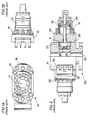
- Fig. 1A is an end view of a conventional ram-type blowout preventer in accordance with the prior art.
- Fig. 1B is a side view of the ram-type blowout preventer shown in Fig. 1A.
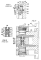
- Fig. 2 is a side view, partially in cutaway, of a ram-type blowout preventer in the prior art that employs a sealing ring for sealing leaks that would otherwise occur between the body and the bonnet of the preventer.
- Fig. 3 is a close up cross-sectional view of area 3 identified in Fig. 2.
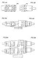
- Fig. 4A is an end view of a lightweight ram-type blowout preventer in accordance with the present invention.
- Fig. 4B is a side view of the preventer shown in Fig. 4A.
- Figs. 5A and 5B represent a side-by-side comparison of a conventional blowout preventer and one of the same pressure capacity in accordance with the present invention.
- Figs. 6A and 6B represent a side-by-side comparison of a conventional dual stack blowout preventer and a lightweight dual stack blowout preventer in accordance with the present invention wherein the lightweight preventer is rated at one and one-half the capacity of the conventional preventer.
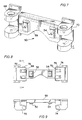
- Fig. 7 is an oblique view of a hinge plate in accordance with the present invention.
- Fig. 8 is a front view of the hinge plate shown in Fig. 7.
- Fig. 9 is a top view of the hinge plate shown in Fig. 8.
- Fig. 10 is a cross-sectional view of a typical fluid hinge of a blowout preventer in the prior art.
- Fig. 11 is a cross-sectional view of a fluid hinge of a blowout preventer in accordance with the present invention.
- Fig. 12 is a blowout preventer in accordance with the present invention illustrating passageways in the hinge plate and in the bonnet housing.
- Fig. 13 is a cross sectional view taken at line 13-13 of Fig. 12.
- Fig. 14 is a close-up lateral cross sectional view of the bonnet housing passageways for the embodiment shown in Fig. 12.
- a conventional bonnet 10 of a ram-type blowout preventer is shown in an end view and a side view, respectively.
- the conventional bonnet 10 is connected to body 12 of the blowout preventer by a plurality of connecting bolts 14 through a suitable wide flange 16 on the bonnet.
- the flange is elongated on either side, as shown in end view Fig. 1A. That is, a full ring of bolts around the elongate axis of the bonnet, which is also the elongate axis of the ram operating within the bonnet, would require a much larger flange to both sides and above and below the structure illustrated.
- FIGs. 2 and 3 selected illustrations are shown from the blowout preventer described in U.S. patent 5,255,890, Morrill, issued October 26, 1993 and commonly assigned herewith. The full disclosure is incorporated herein for all purposes; however, so as to permit an understanding of the structure, a brief description is now set forth.
- Overall preventer 20 comprises a body 21 having a bore 22 therethrough and means such as a flange on its lower end so that it can readily be installed on the upper end of a wellhead and thereby form an upper continuation of the bore to receive drill pipe or other pipe as it is raised or lowered within the wellhead from and to the well below.
- the body has guideways 23 extending from its bore and through the body generally radially opposite one another.
- a ram 24 is slidable within each guideway (only the right guideway is shown) for movement between an inner or closed position and an outer or open position.
- the outer end of each guideway is adapted to be opened and closed by means of a bonnet 25, similar to bonnet 10 of Fig. 1B, releasably connected to the body by means of threaded bolts 26, similar to bolts 14 described in connection with Figs. 1A & 1B.
- the rams are adapted to be moved between open and closed positions by operating means including a cylinder 29 mounted on the outer side of the bonnet 25, and a piston 30 sealably reciprocal in the cylinder and having a rod 31 which extends through a hole in the bonnet to connect with the ram 24.
- hydraulic fluid may be selectively introduced to and exhausted from opposite sides of the piston 30 in the cylinder 29 for selectively moving the ram between its open and closed positions.
- a hinge 32 connects the bonnet to the body for swinging about hinge pin 33 between open and closed positions when it has been disconnected from the body by backing off the bolts 26.
- the outer end of the guideway is suitably enlarged to permit the ram to move freely into and out of the guideway when the ram is in its outer open position.
- inner face 27 of each bonnet has an annular recess formed therein which, as shown, is cylindrical, but which may be of other configuration, such as oval.
- the recess has a peripheral wall 34 and an end wall 35 which is opposite the outer face 21A of the preventer body, and a seal assembly, including a metal ring 36, is mounted in the recess for limited axial and radial movement within the recess. More particularly, the assembly also includes a first elastomeric ring 37 which is received in a groove 38 about the inner side of the metal ring for engaging the outer face 21A of the body.
- the seal ring is an O-ring having a diameter greater than the depth of the recess so as to protrude therefrom, and a wavy spring 39 is received within a groove 41 about the outer side of the metal ring in position to be axially compressed between the bottom of the groove and end wall 35 of the bonnet recess, whereby the metal ring is urged inwardly toward the body face 21A so as to compress seal ring 37 between the face and bottom of the groove in the metal ring.
- the assembly also includes another elastomeric seal ring 40 which is received in a groove 41 about the outer circumference of the metal ring opposite the peripheral wall 34 of the recess.
- this ring 40 is also an O-ring and has a diameter greater than the depth of the groove 41 so as to protrude therefrom and thus sealably engage the wall 34.
- seal rings 37 and 40 may be other than O-rings, such as lips arranged to face the internal pressure.
- means other than the wavy spring 39, such as an O-ring may be compressed axially between the groove and end wall of the recess, may be used to initially urge the inner side of the metal ring against the outer face 21A.
- the O-ring 40 sealably engages the peripheral wall of the recess about an area greater than the area with which the seal ring 37 sealably engages the face 21A of the preventer body.
- fluid pressure in the guideway of the preventer is effective to urge the metal ring inwardly against the face 21A with a force equal to that pressure times an annular area equal to the difference between the outer diameter of the O-ring 40 and the sealing diameter of the seal ring 37.
- the metal ring since the O-ring 40 sealably engages the cylindrical wall 34 outwardly from the preventer body face 21A that is sealably engaged by the O-ring 37, the metal ring is urged radially outwardly toward the wall 34 by a force equal to the internal pressure times an annular area intermediate the sealing engagement of O-ring 37 with face 21A and the sealing engagement of O-ring 40 with wall 34. More particularly, as is previously described, the ring is of such size and shape that the internal pressure will force the inner side of the metal ring tightly against the outer face of the body prior to radial expansion of its periphery against the peripheral wall of the recess.
- the metal ring should not be so thin relative to its length as to be too stiff in an axial direction to conform to the outer face of the preventer body, or to lack sufficient stiffness radially to cause its outer periphery to engage the peripheral wall of the recess too soon and thus lock it within the recess prior to axial movement of its inner side against the face 21A of the body.
- the metal ring should not be so thick in a radial direction as to prevent its outer periphery from conforming to the peripheral wall, following conforming of its inner side against the outer face of the body, so as to close gaps through which seal ring 40 might extrude.
- the areas A f and A o are respectively the unbalanced area of the seal face of the ring and the unbalanced area about the outer periphery of the ring.
- the minimum area A o for a given A f may be calculated in accordance with the following equations, wherein:
- the metal ring 36 is mounted on the bonnet by a pair of spaced-apart bolts 42 which extend through holes 43 in the ring and which are threadedly connected at their inner ends to threaded sockets in the end wall of the recess. As shown, the holes 43 are substantially larger than the diameters of the bolts 42 so as to permit limited radial movement of the metal ring with respect to the bolts, as may be necessary to enable the metal ring to be forced radially outwardly by internal pressure, as previously described.
- the metal ring is retained on the bonnet by an enlarged head 44 received in a recess 45 on the inner side of the metal ring.
- the heads 44 are larger than the holes 43.
- the bolts do not have to be highly torqued in an attempt to minimize pressure leaks in the gap between the body and the bonnet since the pressurized metal ring structure discussed above satisfactorily minimizes or eliminates undesirable leakage. Ordinary torquing in the vicinity of less than 2710 Nm (2000 ft.-lbs.) is satisfactory.
- the bolts themselves can be larger in diameter, but there is a saving in overall weight because of bonnet flange size reduction reduces the overall weight by as much as 20-25%.
- the profile is reduced in size. The reduction of the flange size has the further beneficial effect of reducing the overall stresses in the preventer and, therefore, allows more efficient use of materials overall.
- a comparison of a conventional ram blowout preventer (Fig. 5B) with the same ram operator is shown with the lightweight blowout preventer (Fig. 5A) just described.
- preventers are also made in a stacked configuration wherein two or more ram operators are located operating within respective guideways of the same body.
- Another way of illustrating the great savings effected by the arrangement discussed above is illustrated in Figs. 6A and 6B, wherein a lightweight 476 mm - 1 ⁇ 03 x 10 8 Nm -2 (18-3 ⁇ 4" - 15,000 psi) dual ram-type blowout preventer is shown on the right side in Fig. 6B compared with a conventional 476 mm - 68 ⁇ 9 x 10 6 Nm -2 (18-3 ⁇ 4" - 10,000 psi) ram-type blowout preventer shown on the left side in Fig. 6A.
- the approximate weight of the dual preventer is 22200 kg (49,000 pounds).
- the conventional dual stack is 1 ⁇ 86 m (73.2 inches) high compared with the overall height of the lightweight dual stack that measures 1 ⁇ 9 m (75.0 inches). This means that for about the same weight and height, the capacity of the preventer stack has been increased by 50%. This becomes very important with respect to material handling considerations as well as installation situations.
- the same material handling equipment conventionally able and available for handling the conventional 10,000 psi dual stack can now be used for handling the 15,000 psi dual stack of the lightweight design.
- the same support structure can be used and the same room or space conditions will accept either the 10,000 psi dual stack of conventional design or the 15,000 psi dual stack of the lightweight design.
- available platforms and the like can be used with drilling situations that drill into the deeper and higher pressure zones.
- hinge plate 50 a further convenience for use with the new lightweight designed blowout prevent is shown in hinge plate 50.
- Hinges even fluid hinges that include fluid passageways, have been employed in the prior art for connecting bonnets to the body of a blowout preventer.
- the passageways for opening and closing hydraulic fluid have heretofore been to the body, through the hinge, through the bonnet, to the ram pistons.
- the hinge plate By having a hinge plate with a manifold construction, passageways do not have to be included in the body. Instead, the hinge plate itself becomes a manifold for the passageways leading to the hinges. That is, the opening and closing ports 52 and 54, respectively, for attachment to the opening and closing hydraulic lines (not shown) are included in the hinge plate.
- the passageways are conveniently drilled and plugged in body portion 59 of the hinge plate and in hinge portions 68 and 70. That is, the passageways shown in dotted sections heading from parts 52 and 54, respectively, are straight passageways with 90° bends that are drilled from the most convenient end, top or front surface of the hinge plate and then plugged so that the operating passageways, as shown, remain as the manifold connections.
- the passageways in plate hinge portions 68 and 70 lead to passageways in bonnet hinge portions 72 and 74, respectively.
- each bonnet hinge section includes three arms so as to surround the two arms of the plate hinge section.
- the arms are held in place by a vertical bolt 76 or 78 in much the same fashion as used on common door hinges.
- the center arm of the bonnet hinges in addition to including suitable ports or passageways, also include a suitable balancing sub, as shown in Fig. 11.
- Hinges in the prior art have included a balanced sub arrangement as typified by Fig. 10.
- a central sub 80 with a spring 82 and a spring 84 located on either side provide a mechanical loading to outward seals 86 and 88, respectfully.
- These outward seals include a passageway therethrough and appropriate O-rings to urge the seals against the faces of the adjoining hinge arm in sealing relationships regardless of whether the opening hydraulic fluid or the closing hydraulic fluid is being applied.
- the change of pressure on the side of central sub 80 causes an unbalanced condition that is made up for by the pressure of springs 82 and 84 and the pressurizing of sub 80 to prevent the fluid hinge from leaking.
- Hinge plate 50 provides the capability of hinging both bonnets on the same side, but that hinging can be selected to be on either side. Thus, if there is insufficient room or access to hinge the bonnets on one side in a particular installation, the connecting hinging can be easily provided by installing the plate and the bonnets on the opposite side of the body. Moreover, in a stack arrangement, the bonnets on the body operating with a first ram pair can be conveniently hinged on one side while the bonnets operating with a second ram pair can be conveniently hinged on the opposite side or on the same side, as selectively desired. Hinge plate 50 includes the open and close connecting passageways to the bonnets, as conveniently shown in Figs. 7 and 12.
- the hinge plate and bonnets are conveniently made to be reversible so that when mounted on a first side of the body the "top” of the hinge plate and bonnets are located on the same side as the top side of the body. However, when the hinge plate and bonnets are mounted on the other or second side of the body, the assembly is upside down from its first orientation so that the "top” of the hinge plate and bonnets are now located on the “bottom". Actually, neither the "top” nor the "bottom” of the hinge plate and bonnets are designated top or bottom since these assemblies are completely bidirectional. It is apparent that only one close passageway set and one open passageway set is required for both the hinge plate connecting passageways and the passageways in each of the bonnets because of this reversibility.
- the hydraulic fluid passageways in the bonnets are conveniently located in the housing of the bonnet at locations on either side of the pistons for the respective rams.
- the design is not only simplified, but less material is required for the body than in the prior art. By avoiding a sleeve, potential cumbersome maintenance problems are eliminated.
- FIG. 12 A partial passageway drawing is shown in Fig. 12, wherein hinge plate 59 previously discussed is shown bolted to body 95 of a blowout preventer. As shown by the dotted lines in the hinge plate, opening hydraulic port 52 and closing hydraulic port 54 are connected to appropriate passageways down the hinge plate and through fluid hinge section 72, which is part of bonnet 96.
- Bonnet 96 is conveniently made in multiple parts that includes a section that is attached directly to body 95 via bolts not shown in Fig. 12 but are shown in Fig. 13, an intermediate section 98 that is bolted to the first section via bolts 14B, and a bonnet cap 99 that is bolted to the intermediate section in bolts 14C.
- passageways 100a and 100b within the bonnet leads from the fluid hinge.
- Passageway 100a which is shown in Fig. 12 more to the right than passageway 100b, joins closing passageway 102a.
- Passageway 100b which is parallel to passageway 100a in Fig. 12, joins opening passageway 102b.
- the open space portion of the cylinder or guideway extension 105 shown in Figure 14 in which piston head 103 operates is open to passageway 104.
- Passageway 104 preferably first leads to ram lock 107, which is part of the assembly of parts within the bonnet, as explained in U.S. patents 4,052,995 and 4,290,577, both commonly assigned with the present application.
Claims (25)
- Obturateur à mâchoires, surbaissé léger et à haute pression, pour un puits de pétrole ou de gaz, comprenant un corps (21) pourvu d'une ouverture verticale centrale (22) permettant le passage d'un tubage de forage ou de production, ledit corps (21) incluant également des glissières opposées (23) transversales par rapport à ladite ouverture verticale (22) pour le fonctionnement de mâchoires à commande hydraulique (24) qui ferment et ouvrent ladite ouverture verticale (22), deux capots (96) boulonnés sur ledit corps (21), chacun des dits capots (96) étant pourvu d'une extension de glissière (105) alignée de façon contiguë avec une des dites glissières (23) du dit corps (21), respectivement, afin de recevoir l'extrémité commandée de l'une des dites mâchoires (24), respectivement, deux bagues d'étanchéité métalliques (36) servant respectivement à assurer l'étanchéité contre des fuites de pression à travers un espace respectif entre ledit corps (2) et un des dits capots (96), une mâchoire respective (24) fonctionnant dans chacune des dites glissières (23) dudit corps (21) et des extensions de glissière (105) contiguës de l'un des dits capots (96), chacune des dites mâchoires (24) incluant un piston moteur (103), caractérisé en ce que chaque piston moteur est entouré par une des bagues d'étanchéité métalliques (36), et en ce que l'obturateur comprend, en outre, un petit nombre de boulons (14a) serrés à couple ordinaire servant à relier chacun des dits capots (96) au dit corps (21), le nombre maximum étant de quatre boulons (14a) situés généralement sur les côtés horizontaux opposés d'un axe de mâchoire respectif, de manière que la tenue à la pression de chacun des dits capots (96) par rapport au dit corps (21) dépende de l'une des dites bagues d'étanchéité métalliques (36) respectives et non de l'étanchéité effective produite par les dits boulons (14a) ni de la taille des dits capots (96).
- Obturateur à mâchoires selon la revendication 1, dans lequel lesdits boulons (14a) situés sur chacun des côtés horizontaux opposés d'un axe de mâchoire respectif sont situés à une distance essentiellement égale de l'axe de mâchoire.
- Obturateur à mâchoires selon la revendication 1, dans lequel lesdits boulons (14a) sont serrés selon un couple ne dépassant pas 2710 Nm (2000 pieds-livres).
- Obturateur à mâchoires, comprenant un corps (21) pourvu d'une ouverture verticale centrale (22) permettant le passage d'un tubage de forage ou de production, ledit corps (21) incluant également des glissières opposées (23) transversales par rapport à ladite ouverture verticale (22) pour le fonctionnement de mâchoires à commande hydraulique (24) qui ferment et ouvrent ladite ouverture verticale (22), deux capots boulonnés sur ledit corps (21), chacun des dits capots (96) étant pourvu d'une extension de glissière (105) alignée de façon contiguë avec une des dites glissières (23) du dit corps (21), respectivement, afin de recevoir l'extrémité commandée de l'une des dites mâchoires (24), respectivement, une mâchoire respective (24) fonctionnant dans chacune des dites glissières (23) dudit corps (21) et des extensions de glissière (105) contiguës de l'un des dits capots (96), chacune des dites mâchoires (24) incluant un piston moteur (103), caractérisé en ce que chaque piston moteur est entouré par une bague d'étanchéité métallique (36) servant à assurer l'étanchéité contre des fuites de pression à travers les espaces entre ledit corps (21) et un des dits capots (96), et en ce que l'obturateur comprend, en outre, une plaque à charnières (50) destinée à supporter au moins un des dits capots (96) sur ledit corps (21), ce qui permet de déboulonner ledit capot supporté (96) et de le faire pivoter loin dudit corps (21).
- Obturateur à mâchoires selon la revendication 4, dans lequel ladite plaque à charnières (50) est pourvue d'un collecteur avec un piston de commande (90, 92) pouvant être positionné de manière à appliquer de façon équilibrée un fluide hydraulique de fermeture et d'ouverture à des orifices (100a, 100b) dans les dits capots (96) menant aux dits pistons moteurs (103) des dites mâchoires (24), ladite plaque à charnières (50) incluant également un ressort simple (94) pour appliquer une pression d'étanchéité aux premier et second joints d'étanchéité (86a, 88a) menant des côtés opposés du dit collecteur à des passages respectifs dans ladite plaque à charnières, l'application d'une pression de fluide hydraulique, soit de fermeture, soit d'ouverture, au dit collecteur ayant pour résultat l'application d'une pression d'étanchéité positive supplémentaire à la fois au premier et au second joints d'étanchéité (86a, 88a), et ladite plaque à charnières pouvant être remplacée.
- Obturateur à mâchoires selon la revendication 5, dans lequel ledit piston de commande (90, 92) pouvant être positionné est un sub télescopique centralisé.
- Obturateur à mâchoires selon l'une quelconque des revendications 4 à 6, dans lequel ladite plaque à charnières (5) possède une charnière hydraulique (68), ledit capot (96) étant pourvu de passages hydrauliques correspondant à ladite charnière hydraulique (68) de manière à appliquer le fluide de commande à ladite mâchoire (24) fonctionnant à l'intérieur dudit capot supporté (96), et ladite plaque à charnières (50) étant pourvue d'orifices (52, 54) servant à établir des connexions hydrauliques extérieures pour l'ouverture et la fermeture de ladite mâchoire (24) fonctionnant à l'intérieur dudit capot supporté (96), ladite plaque à charnières (5) comportant des passages hydrauliques intérieurs menant des dits orifices (52, 54) à ladite charnière hydraulique (68) sans traverser également ledit corps (21).
- Obturateur à mâchoires selon la revendication 7, dans lequel ledit capot supporté (96) peut subir une rotation à 180° de manière à placer sur le côté opposé dudit corps (21) ses passages hydrauliques correspondant à ladite charnière hydraulique, et ladite plaque à charnières (50) peut s'adapter pour supporter ledit capot supporté (96) sur le côté opposé dudit corps (21) en étant tournée à l'envers.
- Obturateur à mâchoires selon la revendication 4, dans lequel ladite plaque à charnières (50) est pourvue d'un collecteur avec un piston de commande (92, 94) pouvant être positionné de manière à appliquer de façon équilibrée un fluide hydraulique de fermeture et d'ouverture à des orifices dans les dits capots (96) menant aux dits pistons moteurs (103) des dites mâchoires (24), ladite plaque à charnières (50) pouvant être remplacée, et le premier des dits deux capots (96) étant supporté sur une extrémité de ladite plaque à charnières (50) et le second des dits deux capots (96) étant supporté sur l'extrémité opposée de ladite plaque à charnières (50).
- Obturateur à mâchoires selon la revendication 9, dans lequel ladite plaque à charnières (5) et au moins un des dits capots (96) peuvent être inversés pour être boulonnés sur le côté opposé du dit corps (21).
- Obturateur à mâchoires selon la revendication 9 ou 10, dans lequel ladite plaque à charnières (5) possède une charnière hydraulique (68) sur chacune de ses extrémités pour supporter respectivement les dits capots (96) sur ledit corps (21), ce qui permet de déboulonner respectivement les dits capots supportés (96) et de les faire pivoter loin dudit corps (21), chacun des dits capots (96) étant pourvu de passages hydrauliques correspondant respectivement à une des dites charnières hydrauliques (68), de manière à appliquer le fluide de commande à ladite mâchoire (24) respective fonctionnant à l'intérieur des dits capots supportés (96), respectivement, ladite plaque à charnières (50) étant pourvue d'orifices (52, 54) servant à établir des connexions hydrauliques extérieures pour l'ouverture et la fermeture des dites mâchoires (24) respectives à l'intérieur des dits capots supportés (96) respectifs, ladite plaque à charnières (50) comportant des passages hydrauliques intérieurs menant des dits orifices aux dites charnières hydrauliques (68) respectives sans traverser également ledit corps (21).
- Obturateur à mâchoires selon la revendication 11, dans lequel les dits capots supportés (96) respectifs peuvent subir une rotation à 180° de manière à placer sur le côté opposé dudit corps (21) leurs passages hydrauliques correspondant aux dites charnières hydrauliques (68) respectives, et ladite plaque à charnières (50) peut s'adapter pour supporter les dits capots supportés (96) respectifs sur le côté opposé dudit corps (21) en étant tournée à l'envers.
- Obturateur à mâchoires selon la revendication 4, dans lequel l'obturateur est un bloc obturateur surbaissé étagé léger, à haute pression, pour un puits de pétrole ou de gaz, et comprend une seconde paire de glissières opposées (23) situées verticalement sous la première paire de glissières opposées (23) pour le fonctionnement de deux paires de mâchoires (24) qui ferment et ouvrent ladite ouverture verticale (22), les dits deux capots (96) boulonnés sur chaque côté du dit corps (21), comprenant sur chaque côté un premier capot (96) situé au-dessus d'un second capot (96), chacun des dits premiers capots (96) étant pourvu d'une extension de glissière (105) alignée de façon contiguë avec une des glissières de ladite première paire de glissières opposées (23), et chacun des dits seconds capots (96) étant pourvu d'une extension de glissière (105) alignée de façon contiguë avec une des glissières de ladite seconde paire de glissières opposées (23) dudit corps (21), afin de recevoir, respectivement, l'extrémité commandée d'une mâchoire (24) de chacune des dites paires de mâchoires (24), une seconde plaque à charnières (50) destinée à supporter sur ledit corps (21) une seconde paire de capots (96) fonctionnant avec ladite seconde paire de mâchoires (24), ce qui permet de déboulonner ladite seconde paire de capots supportés (96) et de les faire pivoter loin dudit corps (21) en direction de ladite seconde plaque (50).
- Obturateur à mâchoires selon la revendication 13, dans lequel chacune des dites plaques à charnières (50) est pourvue d'un collecteur avec un sub télescopique (90, 92) pouvant être positionné et un ressort (94) sur un côté de manière à appliquer de façon équilibrée un fluide hydraulique de fermeture et d'ouverture à des orifices dans les capots supportés (96) menant aux pistons moteurs (103) respectifs des mâchoires (24) fonctionnant à l'intérieur.
- Obturateur à mâchoires selon la revendication 13, dans lequel chacune des dites plaques à charnières (50) est pourvue d'un collecteur avec un piston de commande (90, 92) pouvant être positionné de manière à appliquer de façon équilibrée un fluide hydraulique de fermeture et d'ouverture à des orifices dans une des dites paires de capots (96) menant aux dits pistons moteurs (103) des dites mâchoires (24), et les dites plaques à charnières (50) pouvant être remplacées, et le premier des dits deux capots (96) de chaque paire respective de capots (96) est supporté sur une extrémité d'une plaque à charnières (50) respective et le second des dits deux capots (96) de chaque paire respective de capots (96) est supporté sur l'extrémité opposée d'une plaque à charnières (50) respective.
- Obturateur à mâchoires selon la revendication 15, dans lequel les dites plaques à charnières (50) sont situées sur le même côté du dit corps (21).
- Obturateur à mâchoires selon la revendication 15, dans lequel les dites plaques à charnières (50) sont situées sur les côtés opposés du dit corps (21).
- Obturateur à mâchoires selon l'une quelconque des revendications 15 à 17, dans lequel chacune des dites plaques à charnières (50) possède une charnière hydraulique (68) sur chacune de ses extrémités pour supporter respectivement les dits capots (96) respectifs sur ledit corps (21), ce qui permet de déboulonner respectivement les dits capots supportés (96) et de les faire pivoter loin dudit corps (21), chacun des dits capots (96) étant pourvu de passages hydrauliques correspondant à une des dites charnières hydrauliques (68), respectivement, de manière à appliquer le fluide de commande à ladite mâchoire (24) respective fonctionnant à l'intérieur des dits capots supportés (96), respectivement, chacune des dites plaques à charnières (50) étant pourvue d'orifices (52, 54) servant à établir des connexions hydrauliques extérieures pour l'ouverture et la fermeture des dites mâchoires (24) respectives à l'intérieur des dits capots supportés (96) respectifs, chacune des dites plaques à charnières (50) comportant des passages hydrauliques intérieurs menant des dits orifices (52, 54) respectifs aux dites charnières hydrauliques (68) respectives sans traverser également ledit corps (21).
- Obturateur à mâchoires selon la revendication 18, dans lequel les dits capots supportés (96) respectifs peuvent subir une rotation à 180° de manière à placer sur le côté opposé dudit corps (21) leurs passages hydrauliques correspondant aux dites charnières hydrauliques (68) respectives, et les dites plaques à charnières (50) peuvent s'adapter pour supporter les dits capots supportés (96) respectifs sur le côté opposé dudit corps (21) en étant tournées à l'envers.
- Obturateur à mâchoires selon l'une quelconque des revendications précédentes, dans lequel la bague d'étanchéité (36) ou chaque bague d'étanchéité (36) peut être positionnée dans l'axe de la pression et est expansible radialement sous l'effet de la pression.
- Procédé pour préparer un carter pour un obturateur à mâchoires pour un puits de pétrole ou de gaz, destiné à être utilisé lorsque l'espace latéral contigu disponible est limité, comprenant les étapes qui consistent à prévoir un corps (21) pourvu d'une ouverture verticale centrale (22) permettant le passage d'un tubage de forage ou de production, ledit corps (21) incluant également une paire de glissières opposées (23) transversales par rapport à ladite ouverture verticale (22) pour le fonctionnement d'une paire de mâchoires (24) qui ferment et ouvrent ladite ouverture verticale (22), prévoir un premier capot (96) qui va être boulonné sur un premier côté dudit corps (21) et un second capot (96) qui va être boulonné sur un second côté dudit corps (21) opposé au dit premier côté, chacun des dits capots (96) étant pourvu d'une extension de glissière (105) alignée de façon contiguë avec une des dites glissières opposées (23) afin de recevoir l'extrémité commandée d'une mâchoire (24) de ladite paire de mâchoires (24), respectivement, caractérisé en ce que l'on prévoit une plaque à charnières (50) couvrant un côté sélectionné du dit corps (21) afin d'articuler les dits premier et second capots (96) sur ledit corps (21), ce qui permet de déboulonner chacun des dits capots (96) et de les faire pivoter en direction de ladite plaque à charnières (50).
- Procédé pour préparer un carter étagé pour un obturateur à mâchoires selon la revendication 21 pour un puits de pétrole ou de gaz, destiné à être utilisé lorsque l'espace latéral contigu disponible est limité, caractérisé en ce que l'on prévoit une seconde paire de glissières opposées (23) pour le fonctionnement des deux paires de mâchoires (24) qui ferment et ouvrent ladite ouverture verticale (22), en ce qu'on prévoit un troisième et un quatrième capots (96), les dits troisième et quatrième capots (96) étant situés, sur chaque côté, au-dessus des premier et second capots (96), respectivement, chacun des dits troisième et quatrième capots (96) étant pourvu d'une extension de glissière (105) alignée de façon contiguë avec une des glissières de ladite seconde paire de glissières opposées (23), en ce qu'on prévoit une seconde plaque à charnières (50) couvrant un côté sélectionné du dit corps (21) afin d'articuler chaque capot de la paire des troisième et quatrième capots (96) sur ledit corps (21), ce qui permet de déboulonner chacun des dits troisième et quatrième capots (96) et de les faire pivoter en direction de ladite seconde plaque (50).
- Procédé selon la revendication 21 ou 22, comprenant l'étape qui consiste à prévoir pour la ou chaque plaque à charnières (50) une pluralité de passages reliant l'application d'un fluide hydraulique d'ouverture et de fermeture au(x) dit(s) capot(s) (96) respectif(s) à travers les parties de charnière respectives (68) de la ou de chaque plaque à charnières (50).
- Procédé selon la revendication 21 ou 22, comprenant l'étape qui consiste à prévoir pour la ou chaque plaque à charnières (50) et pour chacun des dits capots (96) des dimensions uniformes de manière à pouvoir les inverser pour les fixer de manière sélective sur l'un ou l'autre des deux côtés opposés du dit corps (21).
- Carter pour un obturateur à mâchoires pour un puits de pétrole ou de gaz, comprenant un corps (21) pourvu d'une ouverture verticale centrale (22) permettant le passage d'un tubage de forage ou de production, ledit corps (21) incluant également une paire de glissières opposées (23) transversales par rapport à ladite ouverture verticale (22) pour le fonctionnement d'une paire de mâchoires (24) qui ferment et ouvrent ladite ouverture verticale (22), un capot (96) boulonné sur chaque côté dudit corps (21), chacun des dits capots (96) étant pourvu d'une extension de glissière (105) alignée de façon contiguë avec une des dites glissières opposées (23) du dit corps (21), afin de recevoir l'extrémité commandée d'une mâchoire de ladite paire de mâchoires (24), respectivement, caractérisé en ce que le carter comprend, en outre, une plaque à charnières (50) destinée à supporter les deux capots de la paire des dits capots (96) sur un côté sélectionné du dit corps (21), ce qui permet de déboulonner ladite paire de capots (96) et de les faire pivoter loin dudit corps (21) en direction de ladite plaque à charnières (50).
Applications Claiming Priority (3)
| Application Number | Priority Date | Filing Date | Title |
|---|---|---|---|
| US37239795A | 1995-01-13 | 1995-01-13 | |
| US372397 | 1995-01-13 | ||
| PCT/US1996/000839 WO1996021795A1 (fr) | 1995-01-13 | 1996-01-16 | Bloc obturateur haute pression leger et compact |
Publications (2)
| Publication Number | Publication Date |
|---|---|
| EP0801705A1 EP0801705A1 (fr) | 1997-10-22 |
| EP0801705B1 true EP0801705B1 (fr) | 2002-04-17 |
Family
ID=23467936
Family Applications (1)
| Application Number | Title | Priority Date | Filing Date |
|---|---|---|---|
| EP96903612A Expired - Lifetime EP0801705B1 (fr) | 1995-01-13 | 1996-01-16 | Bloc obturateur haute pression leger et compact |
Country Status (7)
| Country | Link |
|---|---|
| US (5) | US5647572A (fr) |
| EP (1) | EP0801705B1 (fr) |
| AT (1) | ATE216461T1 (fr) |
| DE (1) | DE69620738T2 (fr) |
| DK (1) | DK0801705T3 (fr) |
| ES (1) | ES2179176T3 (fr) |
| WO (1) | WO1996021795A1 (fr) |
Cited By (1)
| Publication number | Priority date | Publication date | Assignee | Title |
|---|---|---|---|---|
| EP3144467A3 (fr) * | 2015-09-08 | 2017-06-14 | Axon EP, Inc. | Obturateur anti-éruption à couvercle articulé |
Families Citing this family (76)
| Publication number | Priority date | Publication date | Assignee | Title |
|---|---|---|---|---|
| GB0107910D0 (en) * | 2001-03-29 | 2001-05-23 | Isis Innovation | Deployable stent |
| US7357187B2 (en) * | 2001-05-04 | 2008-04-15 | Hydril Company Lp | BOP conversion apparatus |
| US6510897B2 (en) * | 2001-05-04 | 2003-01-28 | Hydril Company | Rotational mounts for blowout preventer bonnets |
| US7413019B2 (en) * | 2001-05-04 | 2008-08-19 | Hydril Usa Manufacturing Llc | Mounts for blowout preventer bonnets |
| US7096960B2 (en) * | 2001-05-04 | 2006-08-29 | Hydrill Company Lp | Mounts for blowout preventer bonnets |
| US6554247B2 (en) | 2001-05-04 | 2003-04-29 | Hydril Company | Quick release blowout preventer bonnet |
| US6845959B2 (en) | 2001-05-04 | 2005-01-25 | Hydril Company, L.P. | Quick release blowout preventer bonnet |
| US6651746B2 (en) * | 2001-11-26 | 2003-11-25 | Anthony R. Boyd | High torque and high capacity rotatable center core and floatable sealed body assemblies with universals ram applications and method |
| US6637516B1 (en) * | 2001-11-26 | 2003-10-28 | Anthony R. Boyd | High torque and high capacity rotatable center core and floatable sealed body assemblies with universal RAM applications and method |
| US7086467B2 (en) * | 2001-12-17 | 2006-08-08 | Schlumberger Technology Corporation | Coiled tubing cutter |
| US7699554B2 (en) | 2003-06-03 | 2010-04-20 | Hydril Usa Manufacturing Llc | Removable seal carrier for blowout preventer bonnet assembly |
| US7287544B2 (en) * | 2003-10-21 | 2007-10-30 | Varco I/P, Inc. | Triple valve blow out preventer |
| CN100417850C (zh) * | 2003-10-21 | 2008-09-10 | 瓦克I/P公司 | 内防喷器 |
| EP2518259B1 (fr) * | 2003-12-31 | 2014-08-13 | Varco I/P, Inc. | Vanne de bloc obturateur interne instrumentée pour mesurer des paramètres de forage du train de forage |
| US7234530B2 (en) * | 2004-11-01 | 2007-06-26 | Hydril Company Lp | Ram BOP shear device |
| US7703739B2 (en) * | 2004-11-01 | 2010-04-27 | Hydril Usa Manufacturing Llc | Ram BOP shear device |
| US8424607B2 (en) | 2006-04-25 | 2013-04-23 | National Oilwell Varco, L.P. | System and method for severing a tubular |
| US8720565B2 (en) | 2006-04-25 | 2014-05-13 | National Oilwell Varco, L.P. | Tubular severing system and method of using same |
| US8720564B2 (en) | 2006-04-25 | 2014-05-13 | National Oilwell Varco, L.P. | Tubular severing system and method of using same |
| US7367396B2 (en) | 2006-04-25 | 2008-05-06 | Varco I/P, Inc. | Blowout preventers and methods of use |
| US8702106B2 (en) * | 2006-07-20 | 2014-04-22 | Hydril Usa Manufacturing Llc | Pressure energized radial seal |
| US7721401B2 (en) * | 2006-09-28 | 2010-05-25 | Hydril Usa Manufacturing Llc | Reinforcement of irregular pressure vessels |
| US7849599B2 (en) * | 2006-09-28 | 2010-12-14 | Hydril Usa Manufacturing Llc | Imputing strength gradient in pressure vessels |
| US20080105340A1 (en) * | 2006-11-02 | 2008-05-08 | Huff Philip A | Heat Treatment Method of Inlaid Pressure Vessels |
| US20080105341A1 (en) * | 2006-11-02 | 2008-05-08 | Huff Philip A | Heat treatment of inlaid pressure vessels |
| US20080078081A1 (en) * | 2006-09-28 | 2008-04-03 | Huff Philip A | High pressure-rated ram blowout preventer and method of manufacture |
| US20080105436A1 (en) * | 2006-11-02 | 2008-05-08 | Schlumberger Technology Corporation | Cutter Assembly |
| US7980305B2 (en) * | 2007-02-16 | 2011-07-19 | Hydril Usa Manufacturing Llc | Ram BOP position sensor |
| US7832706B2 (en) * | 2007-02-16 | 2010-11-16 | Hydrill USA Manufacturing LLC | RAM BOP position sensor |
| US9089928B2 (en) | 2008-08-20 | 2015-07-28 | Foro Energy, Inc. | Laser systems and methods for the removal of structures |
| US8820434B2 (en) | 2008-08-20 | 2014-09-02 | Foro Energy, Inc. | Apparatus for advancing a wellbore using high power laser energy |
| US9347271B2 (en) | 2008-10-17 | 2016-05-24 | Foro Energy, Inc. | Optical fiber cable for transmission of high power laser energy over great distances |
| US9267330B2 (en) | 2008-08-20 | 2016-02-23 | Foro Energy, Inc. | Long distance high power optical laser fiber break detection and continuity monitoring systems and methods |
| US9664012B2 (en) | 2008-08-20 | 2017-05-30 | Foro Energy, Inc. | High power laser decomissioning of multistring and damaged wells |
| US9242309B2 (en) | 2012-03-01 | 2016-01-26 | Foro Energy Inc. | Total internal reflection laser tools and methods |
| US9669492B2 (en) | 2008-08-20 | 2017-06-06 | Foro Energy, Inc. | High power laser offshore decommissioning tool, system and methods of use |
| US9719302B2 (en) | 2008-08-20 | 2017-08-01 | Foro Energy, Inc. | High power laser perforating and laser fracturing tools and methods of use |
| US10301912B2 (en) * | 2008-08-20 | 2019-05-28 | Foro Energy, Inc. | High power laser flow assurance systems, tools and methods |
| US9138786B2 (en) | 2008-10-17 | 2015-09-22 | Foro Energy, Inc. | High power laser pipeline tool and methods of use |
| US8627901B1 (en) | 2009-10-01 | 2014-01-14 | Foro Energy, Inc. | Laser bottom hole assembly |
| US9027668B2 (en) | 2008-08-20 | 2015-05-12 | Foro Energy, Inc. | Control system for high power laser drilling workover and completion unit |
| US9360631B2 (en) | 2008-08-20 | 2016-06-07 | Foro Energy, Inc. | Optics assembly for high power laser tools |
| US8571368B2 (en) | 2010-07-21 | 2013-10-29 | Foro Energy, Inc. | Optical fiber configurations for transmission of laser energy over great distances |
| US9244235B2 (en) | 2008-10-17 | 2016-01-26 | Foro Energy, Inc. | Systems and assemblies for transferring high power laser energy through a rotating junction |
| US9080425B2 (en) | 2008-10-17 | 2015-07-14 | Foro Energy, Inc. | High power laser photo-conversion assemblies, apparatuses and methods of use |
| US8220773B2 (en) * | 2008-12-18 | 2012-07-17 | Hydril Usa Manufacturing Llc | Rechargeable subsea force generating device and method |
| US8844898B2 (en) | 2009-03-31 | 2014-09-30 | National Oilwell Varco, L.P. | Blowout preventer with ram socketing |
| US8684088B2 (en) * | 2011-02-24 | 2014-04-01 | Foro Energy, Inc. | Shear laser module and method of retrofitting and use |
| US8783360B2 (en) | 2011-02-24 | 2014-07-22 | Foro Energy, Inc. | Laser assisted riser disconnect and method of use |
| US8783361B2 (en) | 2011-02-24 | 2014-07-22 | Foro Energy, Inc. | Laser assisted blowout preventer and methods of use |
| US8720584B2 (en) | 2011-02-24 | 2014-05-13 | Foro Energy, Inc. | Laser assisted system for controlling deep water drilling emergency situations |
| US8230931B2 (en) * | 2009-12-29 | 2012-07-31 | Hydril Usa Manufacturing Llc | Lifting device and method for lifting a bonnet |
| AU2011256976B2 (en) | 2010-05-28 | 2015-05-21 | National Oilwell Varco, L.P. | Tubular severing system and method of using same |
| US9428994B2 (en) | 2010-07-01 | 2016-08-30 | National Oilwell Varco, L.P. | Blowout preventer monitor with trigger sensor and method of using same |
| CN103025995B (zh) | 2010-07-01 | 2016-11-16 | 国民油井华高公司 | 防喷器监控系统及其使用方法 |
| US8540017B2 (en) | 2010-07-19 | 2013-09-24 | National Oilwell Varco, L.P. | Method and system for sealing a wellbore |
| US8544538B2 (en) | 2010-07-19 | 2013-10-01 | National Oilwell Varco, L.P. | System and method for sealing a wellbore |
| CA2808214C (fr) | 2010-08-17 | 2016-02-23 | Foro Energy Inc. | Systemes et structures d'acheminement destines a une emission laser longue distance a haute puissance |
| US8807219B2 (en) | 2010-09-29 | 2014-08-19 | National Oilwell Varco, L.P. | Blowout preventer blade assembly and method of using same |
| EP2678512A4 (fr) | 2011-02-24 | 2017-06-14 | Foro Energy Inc. | Procédé de forage mécanique-laser de grande puissance |
| WO2012116155A1 (fr) | 2011-02-24 | 2012-08-30 | Foro Energy, Inc. | Moteur électrique pour forage laser-mécanique |
| CN103502565B (zh) | 2011-03-09 | 2016-03-09 | 国民油井华高公司 | 用于密封井眼的方法及设备 |
| EP2715887A4 (fr) | 2011-06-03 | 2016-11-23 | Foro Energy Inc | Connecteurs optiques robustes à fibre laser d'énergie élevée passivement refroidie et procédés d'utilisation |
| SG11201406396RA (en) * | 2012-04-10 | 2014-11-27 | Nat Oilwell Varco Lp | Blowout preventer seal assembly and method of using same |
| CN102704885A (zh) * | 2012-06-18 | 2012-10-03 | 盐城华亚石油机械制造有限公司 | 多用途封井器 |
| EP2890859A4 (fr) | 2012-09-01 | 2016-11-02 | Foro Energy Inc | Systèmes de commande de puits d'énergie mécanique réduite et procédés d'utilisation |
| EP2959096B1 (fr) | 2013-02-21 | 2018-05-16 | National Oilwell Varco, L.P. | Système de surveillance d'un bloc obturateur de puits et son procédé d'utilisation |
| DE102013217383A1 (de) | 2013-08-30 | 2015-03-19 | Klaus Biester | Blowout-Preventer Stack und Versorgungssystem |
| CN104060963A (zh) * | 2014-06-05 | 2014-09-24 | 宝鸡石油机械有限责任公司 | 修井钻井用一体式防喷器 |
| CN104912509B (zh) * | 2015-04-22 | 2017-08-08 | 北京敏秋科技有限公司 | 一种快装卸可调偏斜多级密封防喷装置 |
| CN104847296A (zh) * | 2015-04-30 | 2015-08-19 | 顾军锋 | 防喷器的铰链座 |
| US10746205B2 (en) | 2015-08-06 | 2020-08-18 | National Oilwell Varco, L.P. | Flow responsiveness enhancer for a blowout preventer |
| USD782542S1 (en) | 2015-09-08 | 2017-03-28 | Axon Pressure Products, Inc. | Hinged bonnet for a blowout preventer |
| US10221687B2 (en) | 2015-11-26 | 2019-03-05 | Merger Mines Corporation | Method of mining using a laser |
| DE102016216469A1 (de) | 2016-08-31 | 2018-03-01 | Klaus Biester | Blowout-Preventer Stack |
| WO2024091454A1 (fr) * | 2022-10-28 | 2024-05-02 | Schlumberger Technology Corporation | Distributeur de câbles métalliques à orifice interne |
Citations (1)
| Publication number | Priority date | Publication date | Assignee | Title |
|---|---|---|---|---|
| US4437643A (en) * | 1981-06-25 | 1984-03-20 | Cameron Iron Works, Inc. | Ram-type blowout preventer |
Family Cites Families (7)
| Publication number | Priority date | Publication date | Assignee | Title |
|---|---|---|---|---|
| US3658287A (en) * | 1970-12-04 | 1972-04-25 | Hydril Co | Swinging blowout preventer head with fluid connector |
| US4052995A (en) * | 1975-08-19 | 1977-10-11 | Hydril Company | Blowout preventer ram lock and locking method |
| US4253638A (en) * | 1979-08-02 | 1981-03-03 | Cameron Iron Works, Inc. | Blowout preventer |
| US4290577A (en) * | 1979-09-24 | 1981-09-22 | Hydril Company | Blowout preventer ram lock |
| US4582293A (en) * | 1982-01-06 | 1986-04-15 | Koomey Blowout Preventers, Inc. | Hydraulically operated valves |
| US4456215A (en) * | 1982-05-07 | 1984-06-26 | Bowen Tools, Inc. | Inner seal and support rod assembly for high pressure blowout preventers |
| US5255890A (en) * | 1992-11-12 | 1993-10-26 | Hydril Company | Ram type blowout preventer |
-
1996
- 1996-01-16 EP EP96903612A patent/EP0801705B1/fr not_active Expired - Lifetime
- 1996-01-16 AT AT96903612T patent/ATE216461T1/de not_active IP Right Cessation
- 1996-01-16 WO PCT/US1996/000839 patent/WO1996021795A1/fr active IP Right Grant
- 1996-01-16 ES ES96903612T patent/ES2179176T3/es not_active Expired - Lifetime
- 1996-01-16 DE DE69620738T patent/DE69620738T2/de not_active Expired - Lifetime
- 1996-01-16 DK DK96903612T patent/DK0801705T3/da active
- 1996-02-09 US US08/599,245 patent/US5647572A/en not_active Expired - Lifetime
- 1996-02-09 US US08/598,811 patent/US5655745A/en not_active Expired - Lifetime
- 1996-02-09 US US08/599,177 patent/US5638855A/en not_active Expired - Lifetime
- 1996-02-09 US US08/599,246 patent/US5645098A/en not_active Expired - Lifetime
- 1996-02-09 US US08/598,812 patent/US5642872A/en not_active Expired - Lifetime
Patent Citations (1)
| Publication number | Priority date | Publication date | Assignee | Title |
|---|---|---|---|---|
| US4437643A (en) * | 1981-06-25 | 1984-03-20 | Cameron Iron Works, Inc. | Ram-type blowout preventer |
Cited By (1)
| Publication number | Priority date | Publication date | Assignee | Title |
|---|---|---|---|---|
| EP3144467A3 (fr) * | 2015-09-08 | 2017-06-14 | Axon EP, Inc. | Obturateur anti-éruption à couvercle articulé |
Also Published As
| Publication number | Publication date |
|---|---|
| DE69620738D1 (de) | 2002-05-23 |
| WO1996021795A1 (fr) | 1996-07-18 |
| US5645098A (en) | 1997-07-08 |
| ATE216461T1 (de) | 2002-05-15 |
| ES2179176T3 (es) | 2003-01-16 |
| DK0801705T3 (da) | 2002-08-19 |
| US5647572A (en) | 1997-07-15 |
| US5655745A (en) | 1997-08-12 |
| US5642872A (en) | 1997-07-01 |
| US5638855A (en) | 1997-06-17 |
| DE69620738T2 (de) | 2002-11-21 |
| EP0801705A1 (fr) | 1997-10-22 |
Similar Documents
| Publication | Publication Date | Title |
|---|---|---|
| EP0801705B1 (fr) | Bloc obturateur haute pression leger et compact | |
| US10233716B2 (en) | Blowout preventer including blind seal assembly | |
| US11187054B2 (en) | BOP booster piston assembly and method | |
| US7281586B2 (en) | Mounts for blowout preventer bonnets | |
| USRE37538E1 (en) | Ram type blowout preventer | |
| US5653418A (en) | Ram-type blowout preventer | |
| US20020162663A1 (en) | Rotational mounts for blowout preventer bonnets | |
| US7413019B2 (en) | Mounts for blowout preventer bonnets | |
| GB2154262A (en) | Ram type blowout preventer | |
| US20100258294A1 (en) | Slip spool assembly and method of using same | |
| US5863022A (en) | Stripper/packer and blowout preventer with split bonnet | |
| US7357187B2 (en) | BOP conversion apparatus | |
| US5931443A (en) | Method of rebuilding annular-type blow out preventer | |
| GB2275704A (en) | Wellhead apparatus | |
| US11668154B2 (en) | Variable bore ram assembly | |
| US11549327B2 (en) | Blowout preventer and method | |
| NO20211149A1 (en) | Device for connection or release of bop ram actuator |
Legal Events
| Date | Code | Title | Description |
|---|---|---|---|
| PUAI | Public reference made under article 153(3) epc to a published international application that has entered the european phase |
Free format text: ORIGINAL CODE: 0009012 |
|
| 17P | Request for examination filed |
Effective date: 19970813 |
|
| AK | Designated contracting states |
Kind code of ref document: A1 Designated state(s): AT DE DK ES FR GB IE IT NL SE |
|
| 17Q | First examination report despatched |
Effective date: 19991108 |
|
| GRAG | Despatch of communication of intention to grant |
Free format text: ORIGINAL CODE: EPIDOS AGRA |
|
| GRAG | Despatch of communication of intention to grant |
Free format text: ORIGINAL CODE: EPIDOS AGRA |
|
| GRAH | Despatch of communication of intention to grant a patent |
Free format text: ORIGINAL CODE: EPIDOS IGRA |
|
| GRAH | Despatch of communication of intention to grant a patent |
Free format text: ORIGINAL CODE: EPIDOS IGRA |
|
| REG | Reference to a national code |
Ref country code: GB Ref legal event code: IF02 |
|
| GRAA | (expected) grant |
Free format text: ORIGINAL CODE: 0009210 |
|
| AK | Designated contracting states |
Kind code of ref document: B1 Designated state(s): AT DE DK ES FR GB IE IT NL SE |
|
| REF | Corresponds to: |
Ref document number: 216461 Country of ref document: AT Date of ref document: 20020515 Kind code of ref document: T |
|
| REG | Reference to a national code |
Ref country code: IE Ref legal event code: FG4D |
|
| REF | Corresponds to: |
Ref document number: 69620738 Country of ref document: DE Date of ref document: 20020523 |
|
| REG | Reference to a national code |
Ref country code: DK Ref legal event code: T3 |
|
| ET | Fr: translation filed | ||
| PG25 | Lapsed in a contracting state [announced via postgrant information from national office to epo] |
Ref country code: IE Free format text: LAPSE BECAUSE OF NON-PAYMENT OF DUE FEES Effective date: 20030116 Ref country code: AT Free format text: LAPSE BECAUSE OF NON-PAYMENT OF DUE FEES Effective date: 20030116 |
|
| REG | Reference to a national code |
Ref country code: ES Ref legal event code: FG2A Ref document number: 2179176 Country of ref document: ES Kind code of ref document: T3 |
|
| PG25 | Lapsed in a contracting state [announced via postgrant information from national office to epo] |
Ref country code: SE Free format text: LAPSE BECAUSE OF NON-PAYMENT OF DUE FEES Effective date: 20030117 Ref country code: ES Free format text: LAPSE BECAUSE OF NON-PAYMENT OF DUE FEES Effective date: 20030117 |
|
| PG25 | Lapsed in a contracting state [announced via postgrant information from national office to epo] |
Ref country code: DK Free format text: LAPSE BECAUSE OF NON-PAYMENT OF DUE FEES Effective date: 20030131 |
|
| PLBE | No opposition filed within time limit |
Free format text: ORIGINAL CODE: 0009261 |
|
| STAA | Information on the status of an ep patent application or granted ep patent |
Free format text: STATUS: NO OPPOSITION FILED WITHIN TIME LIMIT |
|
| 26N | No opposition filed |
Effective date: 20030120 |
|
| PG25 | Lapsed in a contracting state [announced via postgrant information from national office to epo] |
Ref country code: NL Free format text: LAPSE BECAUSE OF NON-PAYMENT OF DUE FEES Effective date: 20030801 |
|
| EUG | Se: european patent has lapsed | ||
| REG | Reference to a national code |
Ref country code: DK Ref legal event code: EBP |
|
| NLV4 | Nl: lapsed or anulled due to non-payment of the annual fee |
Effective date: 20030801 |
|
| REG | Reference to a national code |
Ref country code: IE Ref legal event code: MM4A |
|
| REG | Reference to a national code |
Ref country code: ES Ref legal event code: FD2A Effective date: 20030117 |
|
| PG25 | Lapsed in a contracting state [announced via postgrant information from national office to epo] |
Ref country code: IT Free format text: LAPSE BECAUSE OF NON-PAYMENT OF DUE FEES Effective date: 20050116 |
|
| REG | Reference to a national code |
Ref country code: GB Ref legal event code: 732E |
|
| REG | Reference to a national code |
Ref country code: FR Ref legal event code: TP |
|
| REG | Reference to a national code |
Ref country code: FR Ref legal event code: PLFP Year of fee payment: 20 |
|
| PGFP | Annual fee paid to national office [announced via postgrant information from national office to epo] |
Ref country code: DE Payment date: 20150128 Year of fee payment: 20 |
|
| PGFP | Annual fee paid to national office [announced via postgrant information from national office to epo] |
Ref country code: FR Payment date: 20150119 Year of fee payment: 20 Ref country code: GB Payment date: 20150127 Year of fee payment: 20 |
|
| REG | Reference to a national code |
Ref country code: DE Ref legal event code: R071 Ref document number: 69620738 Country of ref document: DE |
|
| REG | Reference to a national code |
Ref country code: GB Ref legal event code: PE20 Expiry date: 20160115 |
|
| PG25 | Lapsed in a contracting state [announced via postgrant information from national office to epo] |
Ref country code: GB Free format text: LAPSE BECAUSE OF EXPIRATION OF PROTECTION Effective date: 20160115 |