EP0801345B1 - Circuit for modulo multiplication and exponentiation arithmetic - Google Patents
Circuit for modulo multiplication and exponentiation arithmetic Download PDFInfo
- Publication number
- EP0801345B1 EP0801345B1 EP97105465A EP97105465A EP0801345B1 EP 0801345 B1 EP0801345 B1 EP 0801345B1 EP 97105465 A EP97105465 A EP 97105465A EP 97105465 A EP97105465 A EP 97105465A EP 0801345 B1 EP0801345 B1 EP 0801345B1
- Authority
- EP
- European Patent Office
- Prior art keywords
- arithmetic
- value
- register
- multiplication
- equation
- Prior art date
- Legal status (The legal status is an assumption and is not a legal conclusion. Google has not performed a legal analysis and makes no representation as to the accuracy of the status listed.)
- Expired - Lifetime
Links
Images


Classifications
-
- G—PHYSICS
- G06—COMPUTING; CALCULATING OR COUNTING
- G06F—ELECTRIC DIGITAL DATA PROCESSING
- G06F7/00—Methods or arrangements for processing data by operating upon the order or content of the data handled
- G06F7/60—Methods or arrangements for performing computations using a digital non-denominational number representation, i.e. number representation without radix; Computing devices using combinations of denominational and non-denominational quantity representations, e.g. using difunction pulse trains, STEELE computers, phase computers
- G06F7/72—Methods or arrangements for performing computations using a digital non-denominational number representation, i.e. number representation without radix; Computing devices using combinations of denominational and non-denominational quantity representations, e.g. using difunction pulse trains, STEELE computers, phase computers using residue arithmetic
- G06F7/728—Methods or arrangements for performing computations using a digital non-denominational number representation, i.e. number representation without radix; Computing devices using combinations of denominational and non-denominational quantity representations, e.g. using difunction pulse trains, STEELE computers, phase computers using residue arithmetic using Montgomery reduction
-
- G—PHYSICS
- G06—COMPUTING; CALCULATING OR COUNTING
- G06F—ELECTRIC DIGITAL DATA PROCESSING
- G06F7/00—Methods or arrangements for processing data by operating upon the order or content of the data handled
- G06F7/38—Methods or arrangements for performing computations using exclusively denominational number representation, e.g. using binary, ternary, decimal representation
- G06F7/48—Methods or arrangements for performing computations using exclusively denominational number representation, e.g. using binary, ternary, decimal representation using non-contact-making devices, e.g. tube, solid state device; using unspecified devices
- G06F7/544—Methods or arrangements for performing computations using exclusively denominational number representation, e.g. using binary, ternary, decimal representation using non-contact-making devices, e.g. tube, solid state device; using unspecified devices for evaluating functions by calculation
- G06F7/5443—Sum of products
-
- G—PHYSICS
- G06—COMPUTING; CALCULATING OR COUNTING
- G06F—ELECTRIC DIGITAL DATA PROCESSING
- G06F7/00—Methods or arrangements for processing data by operating upon the order or content of the data handled
- G06F7/38—Methods or arrangements for performing computations using exclusively denominational number representation, e.g. using binary, ternary, decimal representation
- G06F7/48—Methods or arrangements for performing computations using exclusively denominational number representation, e.g. using binary, ternary, decimal representation using non-contact-making devices, e.g. tube, solid state device; using unspecified devices
- G06F7/52—Multiplying; Dividing
- G06F7/523—Multiplying only
- G06F7/53—Multiplying only in parallel-parallel fashion, i.e. both operands being entered in parallel
- G06F7/5324—Multiplying only in parallel-parallel fashion, i.e. both operands being entered in parallel partitioned, i.e. using repetitively a smaller parallel parallel multiplier or using an array of such smaller multipliers
-
- G—PHYSICS
- G06—COMPUTING; CALCULATING OR COUNTING
- G06F—ELECTRIC DIGITAL DATA PROCESSING
- G06F7/00—Methods or arrangements for processing data by operating upon the order or content of the data handled
- G06F7/60—Methods or arrangements for performing computations using a digital non-denominational number representation, i.e. number representation without radix; Computing devices using combinations of denominational and non-denominational quantity representations, e.g. using difunction pulse trains, STEELE computers, phase computers
- G06F7/72—Methods or arrangements for performing computations using a digital non-denominational number representation, i.e. number representation without radix; Computing devices using combinations of denominational and non-denominational quantity representations, e.g. using difunction pulse trains, STEELE computers, phase computers using residue arithmetic
- G06F7/723—Modular exponentiation
Definitions
- the present invention relates to the encryption and decryption technique of information used in the field such as information communication networks, traffic systems, banking facilities, medical services, distribution industries and the like, and more particularly to a circuit and a system for modulo exponentiation arithmetic and an arithmetic method of performing modulo exponentiation arithmetic for realizing the encryption and decryption of the information.
- the encryption and decryption technique of information is being used not only in the information communication field but also in the fields such as traffic systems, banking facilities, medical service, distribution industries and the like. Accordingly, the encryption and decryption technique of this kind is required to be able to realize the high-degree security by a simple principle.
- the "asymmetric cryptograph algorithm” is excellent qualitatively.
- the encryption key and the decryption key are different from each other and one key cannot be calculated easily from the other key.
- the representatives of the asymmetric cryptograph algorithm involve the RSA cryptograph, the Elgamal cryptograph, the Rabin cryptograph and the Williams cryptograph using the modulo exponentiation arithmetic.
- the representatives of the digital signature systems to be standardized involve the RSA signature method, the Elgamal signature method, the Schnorr signature method and the DSA (Digital Signature Algorithm) method, all of which use the modulo exponentiation arithmetic of a long bit length. Accordingly, it is indispensable to develop an arithmetic unit capable of completing the modulo exponentiation arithmetic having a long bit length in a short time in order to realize the digital signature system.
- the RSA cryptograph, the Elgamal cryptograph, the Rabin cryptograph and the Williams cryptograph basically use the modulo exponentiation arithmetic form represented by the following equation (1).
- the equation (1) means that a remainder of X Y divided by N is calculated. Further, in the equation (1), X represents a plaintext to be encrypted (decrypted), and Y and N represent keys for encryption (decryption). X Y modN
- the modulo exponentiation arithmetic can be used to perform the encryption and the decryption of information easily and make it difficult to cryptanalize the keys by lengthening the bit length of operands of X, Y and N.
- M C d modn
- C an encrypted plaintext, that is, a ciphertext.
- e and n represent encryption keys and in the equation (3) d and n decryption keys.
- p and q are relatively prime integers.
- the keys e and n are public keys and d, n and q are secret keys.
- the above equations (4) and (5) both define conditions of numerical values of the modulo exponentiation arithmetic in the encryption algorithm.
- the equation (4) defines that n is a product of large prime numbers p and q which are prime to each other.
- the prime numbers p and q are both odd numbers and accordingly the product n must be naturally an odd number.
- the equation (5) shows that a remainder of a product c ⁇ d of c and d divided by the least common multiple of values obtained by subtracting 1 from p and q shown in the equation (4) is 1.
- the plaintext M is encrypted by means of the equation (2) and the encrypted plaintext M (ciphertext C) is decrypted by means of the equation (3).
- the plaintext MA prepared by the transmitting person A is encrypted by means of the transmitting person's own secret key dA to prepare a signature text CA (signature).
- the public key eB of the person B is used to prepare an encrypted signature text cA (encryption).
- the cA is transmitted to the person B.
- the encrypted signature text cA received by the person B is decrypted by means of the receiving person's own secret key dB (decryption).
- the eB and dB are expressed by the following equation by using a certain integer h.
- eB ⁇ dB h(pB-1)+1
- the public key eA of the transmitting person is used to prepare the plaintext MA (authentication of signature).
- values of e, d and n are determined under condition of the equations (4) and (5) and the modulo exponentiation arithmetic form represented by the equation (1) is used basically, so that plaintext can be encrypted and the encrypted plaintext can be decrypted.
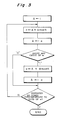
- the iterative square and multiplication method is expressed by a flow chart of Fig. 3.
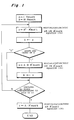
- an initial value 1 is loaded into a register A.
- the value stored in the register A is multiplied by itself to calculate A ⁇ A and the product A ⁇ A is divided by N to obtain a remainder.
- the remainder is stored in a register a.
- the value stored in the register a is loaded into the register A.
- the exponent e is equal to 1
- the value stored in the register A is multiplied by the plaintext M and the product thereof is divided by N to obtain a remainder, which is stored in the register a.
- the contents of the register a is stored into the register A again. If the exponent e is equal to 0, the above calculation is not performed and the value stored in the register A remains as it is without any operation.
- the above calculation is repeatedly performed from the most significant bit to the least significant bit of e, so that the value stored finally into the register A is a solution of the modulo exponentiation arithmetic to be calculated.
- the foundation of the arithmetic is the multiplication and division (modular arithmetic) as shown by the equations (16) and (17).
- the multiplication performs A ⁇ A or A ⁇ M for the value of A having 1 as its initial value and the division performs modN for the value obtained by each multiplication.
- a pair of arithmetic operations of the multiplication and the division are repeated in accordance with bit values of "e". That is, the multiplication and the division are performed in accordance with the contents of bits from the most significant bit to the least significant bit of "e".
- the object of the present invention is to provide the apparatus for performing modular arithmetic more simply and efficiently, in particular according to claims 1 and 8.
- Montgomery has proposed a scheme for obtaining a solution of a modular arithmetic by performing "multiplication" and simple bit string process without performing the modular arithmetic in the general manner as described above.
- the present invention basically utilizes the Montgomery's proposed scheme to perform the arithmetic operation and accordingly the Montgomery's proposed scheme is now described in brief, while measures for shortening an operation time in each arithmetic operation are characteristic of the present invention.
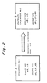
- the flow 2 is a flow for calculating a solution of the modular arithmetic and is not a flow for calculating a solution of the modulo exponentiation arithmetic.
- the solution of the equation (18) is t or t-N obtained by the above function.
- calculation of t of the equation (20) is classified into the following two manners.
- Judgment as to whether X is a multiple of R or not can be made on the basis of whether a value of X less than R is 0 or not. This means that calculation for all of the bit length of X is not required in the calculation of t, so that a calculation amount and a calculation time can be reduced.
- the calculation result of the function REDC(X) is a value in the range of 0 ⁇ t ⁇ 2N and when N ⁇ t, calculation of t-N must be made again as shown in the flow 2.
- the calculation result t of the function REDC(X) performed on the way of the modulo exponentiation arithmetic, when it is within the range of t ⁇ R even if there is the relation of N ⁇ t, the subsequent calculation may be made as it is. The reason is that N value left at this process is removed by the modular arithmetic performed later.
- Bit 4 of t at this time is "0", while a pure solution of the modular arithmetic is not obtained as a value of t itself yet.
- t does not exceed the bit length of N, it is appropriate as a substitution value in the next modulo exponentiation arithmetic of A ⁇ A ⁇ R'modN or A ⁇ M ⁇ R'modN.
- REDC(X) the value having N which has been left
- a ⁇ A ⁇ R'modN is calculated as follows.
- the function REDC for performing the Montgomery's arithmetic shown in the Flow 2 merely obtains the solution of the Montgomery's arithmetic. That is, as shown in the equation (18), in order to facilitate the calculation, a peculiar numerical value of R' is used. In order to obtain the solution of the equation using the multiplication modN form which does not include R', it is necessary to return the solution of the Montgomery's arithmetic shown in the Flow 2 to numerical value which does not include R' by means of any operation.
- M ⁇ RmodN can be obtained by the following calculation using the Montgomery's arithmetic.
- the Flow 2 is executed using the multiplied result as X in the Flow 2 to thereby obtain M ⁇ RmodN.
- the calculation in the Flow 2 includes the multiplication using N and N' and the division using R. Accordingly, the solution can be obtained only by the multiplication and the addition without substantial execution of the division (modular arithmetic).
- the previously obtained RmodN is stored in a register A (The register A may be a memory, for example. The same applies hereinafter.) as an initial value.
- the previously obtained M ⁇ RmodN is stored in a register B.
- the reason why M ⁇ RmodN is stored in the register B is that M ⁇ RmodN in the equation (25) used in the later process is ensured.
- the equation (24) is executed. That is, the Montgomery's arithmetic A 2 ⁇ R'modN is executed.
- the equation (24) is obtained by executing the Flow 2 as described above.
- a value obtained by squaring the value stored in the register A is calculated as X in the equation (19) to obtain m.
- the obtained m is used to execute the equation (20).
- a value obtained by squaring the value stored in the register A is calculated as X in the equation (20) to obtain t.
- bits of the exponent e is made. If bit is 1, the equation (25) is executed. That is, the Montgomery's arithmetic A ⁇ B ⁇ R'modN is executed. The equation (25) is obtained by executing the Flow 2 as described above. A product of the value stored in the register A and the value stored in the register B is calculated as X in the equation (19) to obtain m. The obtained m is used to execute the equation (20). A product of the value stored in the register A and the value stored in the register B is calculated as X in the equation (20) to obtain t. The calculation result is stored in the register a. The calculation result stored in the register a is stored in the register A.
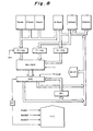
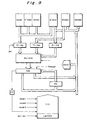
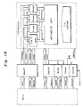
- Fig. 4 is a block diagram schematically illustrating an actual hardware.
- numerals 401, 403, 405, 407, 409, 411, 413 and 415 denote memories or registers. Values described in respective boxes are stored in the registers 401, 403, 405, 407, 409, 411 and 413.
- the register 405 corresponds to the register A described in Fig. 1 and the register 415 corresponds to the register a.
- a selector 417 serves to transfer any output of the register 407 or the register 405 to an arithmetic unit 419 in accordance with an indication from a one-bit left-shift register 409 in which the exponent e is stored.
- the selector 417 corresponds to a portion for executing the "shift and carry of e" in Fig. 1.
- the arithmetic unit 419 includes a multiplier unit and a divider unit.
- the arithmetic unit 419 executes multiplication and the function REDC(X).
- the calculation method of the modulo exponentiation arithmetic M e modN performs the two kinds of arithmetic operations of A 2 ⁇ R'modN ... (24) and A ⁇ B ⁇ R'modN ... (25) (B corresponds to a portion in which "M ⁇ RmodN" of the equation (25) is positioned) in the Montgomery's arithmetic method described above repeatedly on the basis of a prescribed procedure in accordance with contents of bit values of the exponent "e” and finally performs the following equation (26) as described in Fig. 1 and the Flow 3.
- the coprocessor can be used (the repetitive procedure of arithmetic may be realized by a control method of any of software or hardware) to obtain the solution of the modulo exponentiation arithmetic.
- the present invention concerns the coprocessor having the three kinds of modular arithmetics or three arithmetic modes.
- Fig. 5 is a diagram schematically illustrating a modular arithmetic coprocessor according to a first embodiment of the present invention.
- thick arrowed lines connecting blocks represent buses for transferring data.
- the modular arithmetic coprocessor of the present invention comprises a timing/control circuit T/C for supplying operation timings of the whole coprocessor and control signals corresponding to a kind of the arithmetic operations of three kinds to various circuits in arithmetic unit, and a plurality of arithmetic value memories Smem, N'mem, Nmem, Mmem, A'mem, Wlmem and Whmem for storing arithmetic values in the Montgomery's method.
- the modular arithmetic coprocessor of the present invention comprises a high-speed multiplier/adder Mul/Add for performing multiplication and addition, a high-speed adder Add for performing addition, a multiplier storage register Xi-reg for storing a multiplier value, a multiplicand storage register Yi-reg for storing a multiplicand, an augend storage register Ai-reg for storing an augend, and a register RH for storing an upper digit of a value produced by the high-speed adder Add.
- the high-speed adder Add, the multiplier storage register Xi-reg, the multiplicand storage register Yi-reg and the augend storage register Ai-reg have the function of temporarily storing a value read out from the arithmetic value memories and corresponding to an input bit length of the high-speed multiplier/adder Mul/Add.
- the high-speed multiplier/adder Mul/Add is a multiplier/adder of a specific bit length which is supplied with an output value of the register Xi-reg and an output value of the register Yi-reg as input value in the multiplication operation and is supplied with an output value of the register Ai-reg as input value in the addition operation.
- An output of the high-speed multiplier/adder is inputted to the high-speed adder Add of next stage as an addition input value.
- the high-speed adder Add is an adder of a specific bit length which performs addition of an output value of the high-speed multiplier/adder Mul/Add and an output value of the register RH.
- the upper digit of the output of the high-speed adder Add is supplied to the register RH or the arithmetic value memories and the lower digit thereof is supplied to the arithmetic value memories.
- a value of A is stored in both the arithmetic value memories A'mem and Wlmem, a value of N' in the Montgomery's method is stored in the arithmetic value memory N'mem and a value of N is stored in the arithmetic value memory Nmem. Since the values of N and N' are keys for encryption/decryption, the values are determined by the cryptograph system operator to the transmitting/receiving person of data.
- a value of R is determined from the value of N. The value of A is determined by executing RmodN as described above.
- a mode 1 signal is supplied to the timing/control circuit T/C to thereby execute the equation (24) of A 2 ⁇ R'modN as described below.
- a value corresponding to the input bit length of the high-speed multiplier/adder Mul/Add is taken in the register Xi-reg from the arithmetic value memory A'mem.
- a value corresponding to the input bit length of the high-speed multiplier/adder Mul/Add is taken in the register Yi-reg from the arithmetic value memory Wlmem.
- This arithmetic operation means that values obtained by multiplying values stored in addresses A'3, A'2, A'1 and A'0 of the arithmetic value memory A'mem by values stored in addresses Wl3, Wl2, Wl1 and Wl0 are stored in addresses Wh3, Wh2, Wh1, Wh0, Wl3. Wl2, Wl1 and Wl0 of the arithmetic value memories Whmem and Wlmem.
- the value (multiplicand) stored in the address Wl0 of the arithmetic memory Wlmem is taken in the register Yi-reg and the value (multiplier) stored in the address A'0 of the arithmetic value memory A'mem is taken in the register Xi-reg.
- the high-speed multiplier/adder Mul/Add multiplies the multiplier by the multiplicand and supplies a product thereof to the high-speed adder Add.
- the addend supplied to the high-speed multiplier/adder Mul/Add from the register Ai-reg is assumed to be 0.
- the value of the register Ai-reg is set to 0 or the value stored in the register Ai-reg is adapted not to be supplied to the high-speed multiplier/adder Mul/Add.) Further, a high level signal is supplied to a through terminal of the high-speed adder Add so that contents of the register RH are not added.
- the lower digit of the operation result in the unit of multiplication and addition 1 is stored in the least significant address Wl0 of the arithmetic value memory Wlmem as the final operation result of this multiplication.
- the final operation result is stored in the underlined address.
- the upper digit of the operation result of the unit of multiplication and addition 1 is stored in the register RH in order to align the digit in the next unit of multiplication and addition.
- the register Yi-reg holds the already stored value (multiplicand) and the register Xi-reg takes in the value (multiplier) stored in the address A'1 of the arithmetic value memory A'mem. Then, the high-speed multiplier/adder Mul/Add multiplies the multiplier by the multiplicand and supplies the product thereof to the high-speed adder Add. In this multiplication and addition unit 2, the addend supplied to the high-speed multiplier/adder Mul/Add from the register Ai-reg is assumed to be 0.
- the value of the register Ai-reg is set to 0 or the value stored in the register Ai-reg is adapted not to be supplied to the high-speed multiplier/adder Mul/Add.
- a low level signal is supplied to the through terminal of the high-speed adder Add so that contents (the upper digit of the operation result of the multiplication and addition unit 1) of the register RH are added to the output of the high-speed multiplier/adder Mul/Add.
- the lower digit of the operation result in the unit of multiplication and addition 2 is stored in the least significant address Wh0 of the arithmetic value memory Whmem.
- the upper digit of the operation result of the unit of multiplication and addition 2 is stored in the register RH in order to align the digit in the next unit of multiplication and addition.
- the register Yi-reg holds the already stored value (multiplicand) and the register Xi-reg takes in the value (multiplier) stored in the address A'2 of the arithmetic value memory A'mem. Then, the high-speed multiplier/adder Mul/Add multiplies the multiplier by the multiplicand and supplies the product thereof to the high-speed adder Add. In this multiplication and addition unit 3, the addend supplied to the high-speed multiplier/adder Mul/Add from the register Ai-reg is assumed to be 0.
- the value of the register Ai-reg is set to 0 or the value stored in the register Ai-reg is adapted not to be supplied to the high-speed multiplier/adder Mul/Add.
- a low level signal is supplied to the through terminal of the high-speed adder Add so that contents (the upper digit of the operation result of the multiplication and addition unit 1) of the register RH are added to the output of the high-speed multiplier/adder Mul/Add.
- the lower digit of the operation result in the unit of multiplication and addition 3 is stored in the address Wh1 of the arithmetic value memory Whmem.
- the upper digit of the operation result of the unit of multiplication and addition 3 is stored in the register RH in order to align the digit in the next unit of multiplication and addition.
- the register Yi-reg holds the already stored value (multiplicand) and the register Xi-reg takes in the value (multiplier) stored in the address A'3 of the arithmetic value memory A'mem. Then, the high-speed multiplier/adder Mul/Add multiplies the multiplier by the multiplicand and supplies the product thereof to the high-speed adder Add. In this multiplication and addition unit 4, the addend supplied to the high-speed multiplier/adder Mul/Add from the register Ai-reg is assumed to be 0.
- the value of the register Ai-reg is set to 0 or the value stored in the register Ai-reg is adapted not to be supplied to the high-speed multiplier/adder Mul/Add.
- a low level signal is supplied to the through terminal of the high-speed adder Add so that contents (the upper digit of the operation result of the multiplication and addition unit 1) of the register RH are added to the output of the high-speed multiplier/adder Mul/Add.
- the lower digit of the operation result in the unit of multiplication and addition 4 is stored in the address Wh2 of the arithmetic value memory Whmem.
- the upper digit of the operation result of the unit of multiplication and addition 4 is stored in the address Wh3 of the arithmetic value memory Whmem in order to align the digit in the next unit of multiplication and addition.
- the register Yi-reg takes in the value (multiplicand) stored in the address Wl1 of the arithmetic value memory Wlmem
- the register Xi-reg takes in the value (multiplier) stored in the address A'0 of the arithmetic value memory A'mem
- the register Ai-reg takes in the value (addend) stored in the address Wh0 of the arithmetic value memory Whmem.
- a high level signal is supplied to the through terminal of the high-speed adder Add so that the contents (upper digit of the operation result of the unit of multiplication and addition 4) of the register RH are not added.
- the lower digit of the operation result of this multiplication and addition unit 5 is stored in the address Wl1 of the arithmetic value memory Wlmem.
- the upper digit of the operation result of this multiplication and addition unit 5 is stored in the register RH in order to align the digit in the next unit of multiplication and addition.
- the register Yi-reg holds the already stored value (multiplicand), the register Xi-reg takes in the value (multiplier) stored in the address A'1 of the arithmetic value A'mem and the register Ai-reg takes in the value (addend) stored in the address Wh1 of the arithmetic value memory Whmem. Then, the high-speed multiplier/adder Mul/Add multiplies the multiplier by the multiplicand and adds the addend to this multiplication result to supply the added result to the high-speed adder Add.
- a low level signal is supplied to the through terminal of the high-speed adder Add so that the contents (upper digit of the operation result of the unit of multiplication and addition 5) of the register RH are added to the output of the high-speed multiplier/adder Mul/Add.
- the lower digit of the operation result of this multiplication and addition unit 6 is stored in the address Wh0 of the arithmetic value memory Whmem.
- the upper digit of the operation result of this multiplication and addition unit 6 is stored in the register RH in order to align the digit in the next unit of multiplication and addition.
- the register Yi-reg holds the already stored value (multiplicand), the register Xi-reg takes in the value (multiplier) stored in the address A'2 of the arithmetic value A'mem and the register Ai-reg takes in the value (addend) stored in the address Wh2 of the arithmetic value memory Whmem. Then, the high-speed multiplier/adder Mul/Add multiplies the multiplier by the multiplicand and adds the addend to this multiplication result to supply the added result to the high-speed adder Add.
- a low level signal is supplied to the through terminal of the high-speed adder Add so that the contents (upper digit of the operation result of the unit of multiplication and addition 6) of the register RH is added to the output of the high-speed multiplier/adder Mul/Add.
- the lower digit of the operation result of this multiplication and addition unit 7 is stored in the address Wh1 of the arithmetic value memory Whmem.
- the upper digit of the operation result of this multiplication and addition unit 7 is stored in the register RH in order to align the digit in the next unit of multiplication and addition.
- the register Yi-reg holds the already stored value (multiplicand), the register Xi-reg takes in the value (multiplier) stored in the address A'3 of the arithmetic value A'mem and the register Ai-reg takes in the value (addend) stored in the address Wh3 of the arithmetic value memory Whmem. Then, the high-speed multiplier/adder Mul/Add multiplies the multiplier by the multiplicand and adds the addend to this multiplication result to supply the added result to the high-speed adder Add.
- a low level signal is supplied to the through terminal of the high-speed adder Add so that the contents (upper digit of the operation result of the unit of multiplication and addition 7) of the register RH are added to the output of the high-speed multiplier/adder Mul/Add.
- the lower digit of the operation result of this multiplication and addition unit 8 is stored in the address Wh2 of the arithmetic value memory Whmem.
- the upper digit of the operation result of this multiplication and addition unit 8 is stored in the address Wh3 of the arithmetic value memory Whmem.
- a ⁇ A that is, the value obtained by multiplying the value stored in the arithmetic value memory A'mem by the value stored in the arithmetic value memory Wlmem is stored in the form of Whmem-Wlmem ("-" is not a mark representing subtraction).
- the upper digit 65h thereof is stored in the arithmetic value memory Whmem and the lower digit 72h is stored in the arithmetic value memory Wlmem.
- the function REDC is used to perform the modular arithmetic using the Montgomery's method.
- R 2 n as described above.
- the value obtained by the equation (28) is stored in both of the arithmetic value memories A'mem and Mmem. Further, when overflow of digit occurs, 1 is written in a carry flag CF.
- the value of (the inverted Nmem+1) in the equation (29) is obtained by calculating a complement of 1 for Nmem and changing the least significant bit to 1. This operation is realized by supplying 1 to a terminal Inv of the register Xi-reg shown in Fig. 5 (the complement of 1 for the value stored in the register Xi-reg is calculated).
- the value of A is stored in the arithmetic value memory Wlmem
- the value of B is stored in the arithmetic value memory Smem
- the value of N' in the Montgomery's method is stored in the arithmetic value memory N'mem
- the value of N is stored in the arithmetic value memory Nmem.
- a mode 2 signal is supplied to the timing/control circuit T/C to thereby execute the equation (25) of A ⁇ B ⁇ R'modN as described below.
- a value corresponding to the input bit length of the high-speed multiplier/adder Mul/Add is taken in the register Xi-reg from the arithmetic value memory Smem.
- a value corresponding to the input bit length of the high-speed multiplier/adder Mul/Add is taken in the register Yi-reg from the arithmetic value memory Wlmem.
- a ⁇ B is the same as the calculation of A ⁇ A described above except that the value supplied to the register Xi-reg is taken from the arithmetic value memory Smem.
- the function REDC is used to perform the modular arithmetic using the Montgomery's method.
- the calculation method is the same as in the case of A ⁇ A and the calculation result is stored in both of the arithmetic value memories A'mem and Wlmem.
- the equations (24) and (25) are calculated repeatedly.
- the calculation results of the equations (24) and (25) are stored in both of the arithmetic value memories A'mem and Wlmem. Accordingly, since the initialization of arithmetic values is not required at the beginning of calculation of each equation, the repetitive calculation can be performed smoothly.
- the value of A is stored in the arithmetic value memory Wlmem
- the value of N' in the Montgomery's method is stored in the arithmetic value memory N'mem
- the value of N is stored in the arithmetic value memory Nmem.
- a mode 3 signal is supplied to the timing/control circuit T/C to thereby execute the equation (26) of A ⁇ R'modN as described below.
- the calculation method of m in the modular arithmetic is substantially the same as in the case of A ⁇ A.
- the value of the arithmetic value memory Wlmem when the calculation result is stored in both of the arithmetic value memories A'mem and Wlmem in the form of A'mem-Wlmem is the value of m.
- the multiplier/adder (a multiplier and an adder may be provided separately) having the prescribed bit length is provided as a core of the arithmetic unit and the control signals from the timing/control signal generating circuit are supplied to the, circuit disposed at the periphery thereof to thereby be able to realize the modular arithmetic having a long bit length using the Montgomery's method or the modulo exponentiation arithmetic.
- the circuit scale can be made small and it is suitable for LSI.
- Fig. 8 is a block diagram schematically illustrating a modular arithmetic coprocessor according to a second embodiment of the present invention.
- the second embodiment includes, in addition to the configuration of the first embodiment (Fig. 5), a circuit for detecting that an arithmetic value is 0 and controlling the sequence for the next arithmetic operation.
- This control circuit is represented by ZeroC in Fig. 8.
- the control circuit ZeroC is a circuit for detecting that an arithmetic value is 0 to control the sequence for the next arithmetic operation and includes an input terminal to which the output signal of the high-speed adder Add is supplied and an output terminal.
- the control circuit produces from the output terminal a signal for subjecting the timing/control signal generated by the timing/control circuit T/C and the signal for operating the various circuits in the coprocessor to a predetermined control.
- the value of X obtained as the result of the previous multiplication can be classified into the following two cases.
- control circuit ZeroC detects whether the value less than R of the X value (value of A ⁇ A or A ⁇ B) is 0 or not and performs the sequence of the subsequent arithmetic operation in accordance with the detected result as follows.
- the upper digit of the calculated result of A ⁇ A and A ⁇ B is a value of t as it is. Accordingly, in the process by hardware in this case, the value stored in the arithmetic value memory Whmem is stored in both of the arithmetic value memories A'mem and Wlmem as it is and preparation for the next repetitive arithmetic operation is made. That is, when the value less than R of the X value (value obtained by the previous calculation) is 0, it is not necessary to calculate t. This means that it is not necessary to calculate the whole bit length of X in calculation of t.
- the calculation for obtaining m is performed in the same manner as the first embodiment and the calculated result is stored in both of the arithmetic value memories A'mem and Wlmem in the form of A'mem-Wlmem.
- the value stored in the arithmetic value memory Wlmem is made to be the value of m. Calculation of t is continuously performed.
- the solution of the equation (32) is obtained by performing calculation of (Wlmem) ⁇ (Nmem) to store the calculated result in both of the arithmetic value memories A'mem and Wlmem in the form of A'mem-Wlmem and then performing calculation of the following equation. (A'mem) ⁇ 1+(Whmem)+1
- (A'mem) ⁇ 1+(Whmem)+1 The reason is that since the value of X+m ⁇ N is a multiple of R necessarily, it is not necessary to calculate the value less than R purposely.
- 1 is supplied to the terminal +1 shown in Fig. 5 to execute addition of 1 in the equation (33).
- control circuit which can be configured by the circuit scale corresponding to the bit length of the multiplier/adder and is a small-scale circuit
- control circuit for detecting that the arithmetic value is 0 and controlling the sequence of the subsequent arithmetic operation
- Fig. 9 is a block diagram schematically illustrating a modular arithmetic coprocessor according to a third embodiment of the present invention.
- the third embodiment includes, in addition to the configuration of the first embodiment (Fig. 5) or the second embodiment (Fig. 8), a bit length selection control circuit for selecting the bit length of the operand to change the timing/control signal.
- bit length selection control circuit is represented by LenCont of Fig. 9.
- the bit length selection control circuit LenCont is operated to control the operation timing signal generated by the timing/control circuit T/C and the control signal supplied to the various circuits in the coprocessor in accordance with an input signal Sel-len.
- the value R, the value R' determined by the value of R, the bit length of the N' value and the repetitive procedure (the number of times) of the multiplication and addition of the prescribed bit length are changed in accordance with change of the bit length of the operand.
- the high-speed multiplier/adder Mul/Add is of 16-bit length and performs multiplication of A ⁇ A having the operand bit length of 512 bits
- the bit length selection control circuit LenCon controls the factor for the above changes, that is, the circuit controls to produce the operation timing signal and the control signal generated by the timing/control circuit T/C in accordance with the selected bit length.
- bit length selection control circuit LenCont can be realized by a relatively small-scale circuit configuration such as PLA or logic circuits.
- bit length selection control circuit LenCont is added to thereby be able to execute the modular arithmetic or the modulo exponentiation arithmetic having various operand bit lengths.
- the foundation of the arithmetic operation of the coprocessor described in the above embodiments is the multiplication and the addition of the prescribed bit length.
- the method of repeating the basic multiplication and addition to realize the modular arithmetic or the modulo exponentiation arithmetic is as described in the above embodiments.
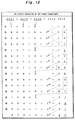
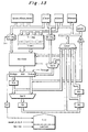
- Fig. 10 is a block diagram schematically illustrating the modular arithmetic coprocessor according to a fourth embodiment of the present invention.
- the multiplication and addition mode is added to the embodiments described above.
- a mode signal 4 is supplied to the timing/control circuit T/C.
- values A, B and C are stored in the arithmetic value memories Wlmem, Smem and Whmem.
- the mode signal 4 is supplied to the timing/control circuit T/C to set the kind of arithmetic operation to the mode of executing multiplication and addition.
- This arithmetic operation means that values obtained by adding values stored in addresses Wh3, Wh2, Wh1 and Wh0 to values obtained by multiplying values stored in addresses S3, S2, S1 and S0 of the arithmetic value memory Smem by values stored in addresses Wl3, Wl2, Wl1 and Wl0 of the arithmetic value memory Wlmem are stored in addresses Wh3, Wh2, Wh1, Wh0, Wl3, Wl2, Wl1 and Wl0 of the arithmetic value memories Whmem and Wlmem.
- the value (multiplicand) stored in address Wl0 of the arithmetic value memory Wlmem is supplied to the register Yi-reg
- the value (multiplier) stored in address S0 of the arithmetic value memory Smem is supplied to the register Xi-reg
- the value (addend) stored in address Wh0 of the arithmetic value memory Whmem is supplied to the register Ai-reg.
- the high-speed multiplier/adder Mul/Add multiplies the multiplier by the multiplicand and adds the multiplied result to the addend to supply the added result to the high-speed adder Add.
- a high level signal is supplied to the through terminal of the high-speed adder Add so that contents of the register RH is not added.
- the lower digit of the operation result in the unit of multiplication and addition is the least significant digit of the final operation result of this multiplication and addition
- the lower digit of the operation result in the unit of multiplication and addition 1 is stored in the least significant address Wl0 of the arithmetic value memory Wlmem as the final operation result of this multiplication. (In Fig. 11, the final operation result is stored in the underlined address.)
- the upper digit of the operation result of the unit of multiplication and addition 1 is stored in the register RH for the next unit of multiplication and addition.
- the register Yi-reg holds the already stored value (multiplicand) and the register Xi-reg takes in the value (multiplier) stored in the address S1 of the arithmetic value memory Smem and the register Ai-reg takes in the value (addend) stored in address Wh1 of the arithmetic value memory Whmem. Then, the high-speed multiplier/adder Mul/Add multiplies the multiplier by the multiplicand and adds the multiplied result to the addend to supply the added result to the high-speed adder Add.
- a low level signal is supplied to the through terminal of the high-speed adder Add so that contents (the upper digit of the operation result of the multiplication and addition unit 1) of the register RH is added to the output of the high-speed multiplier/adder Mul/Add.
- the lower digit of the operation result in the unit of multiplication and addition 2 is stored in the least significant address Wh0 of the arithmetic value memory Whmem.
- the upper digit of the operation result of the unit of multiplication and addition 2 is stored in the register RH in order to align the digit in the next unit of multiplication and addition.
- the register Yi-reg holds the already stored value (multiplicand) and the register Xi-reg takes in the value (multiplier) stored in the address S2 of the arithmetic value memory Smem and the register Ai-reg takes in the value (addend) stored in address Wh2 of the arithmetic value memory Whmem. Then, the high-speed multiplier/adder Mul/Add multiplies the multiplier by the multiplicand and adds the multiplied result to the addend to supply the added result to the high-speed adder Add.
- a low level signal is supplied to the through terminal of the high-speed adder Add so that contents (the upper digit of the operation result of the multiplication and addition unit 2) of the register RH is added to the output of the high-speed multiplier/adder Mul/Add.
- the lower digit of the operation result in the unit of multiplication and addition 3 is stored in the least significant address Wh1 of the arithmetic value memory Whmem.
- the upper digit of the operation result of the unit of multiplication and addition 3 is stored in the register RH in order to align the digit in the next unit of multiplication and addition.
- the register Yi-reg holds the already stored value (multiplicand) and the register Xi-reg takes in the value (multiplier) stored in the address S3 of the arithmetic value memory Smem and the register Ai-reg takes in the value (addend) stored in address Wh3 of the arithmetic value memory Whmem. Then, the high-speed multiplier/adder Mul/Add multiplies the multiplier by the multiplicand and adds the multiplied result to the addend to supply the added result to the high-speed adder Add.
- a low level signal is supplied to the through terminal of the high-speed adder Add so that contents (the upper digit of the operation result of the multiplication and addition unit 3) of the register RH is added to the output of the high-speed multiplier/adder Mul/Add.
- the lower digit of the operation result in the unit of multiplication and addition 4 is stored in the least significant address Wh2 of the arithmetic value memory Whmem.
- the upper digit of the operation result of the unit of multiplication and addition 4 is stored in address Wh3 of the arithmetic value memory Whmem in order to align the digit in the next unit of multiplication and addition.
- the value (multiplicand) stored in address Wl1 of the arithmetic value memory Wlmem is supplied to the register Yi-reg
- the value (multiplier) stored in address S0 of the arithmetic value memory Smem is supplied to the register Xi-reg
- the value (addend) stored in address Wh0 of the arithmetic value memory Whmem is supplied to the register Ai-reg.
- the high-speed multiplier/adder Mul/Add multiplies the multiplier by the multiplicand and adds the multiplied result to the addend to supply the added result to the high-speed adder Add.
- this multiplication and addition unit 5 a high level signal is supplied to the through terminal of the high-speed adder Add so that contents (upper digit of the operation result of the multiplication and addition unit 4) of the register RH is not added.
- the least significant digit of the operation result of the multiplication and addition unit 5 is stored in address Wl1 of the arithmetic value memory Wlmem.
- the most significant digit of the operation result of the multiplication and addition unit 5 is stored in the register RH in order to align the digit in the next unit of multiplication and addition.
- the register Yi-reg holds the already stored value (multiplicand) and the register Xi-reg takes in the value (multiplier) stored in the address S1 of the arithmetic value memory Smem and the register Ai-reg takes in the value (addend) stored in address Wh1 of the arithmetic value memory Whmem. Then, the high-speed multiplier/adder Mul/Add multiplies the multiplier by the multiplicand and adds the multiplied result to the addend to supply the added result to the high-speed adder Add.
- this multiplication and addition unit 6 a low level signal is supplied to the through terminal of the high-speed adder Add so that contents (the upper digit of the operation result of the multiplication and addition unit 5) of the register RH is added to the output of the high-speed multiplier/adder Mul/Add.
- the lower digit of the operation result in the unit of multiplication and addition 6 is stored in address Wh0 of the arithmetic value memory Whmem.
- the upper digit of the operation result of the unit of multiplication and addition 6 is stored in the register RH in order to align the digit in the next unit of multiplication and addition.
- the register Yi-reg holds the already stored value (multiplicand) and the register Xi-reg takes in the value (multiplier) stored in the address S2 of the arithmetic value memory Smem and the register Ai-reg takes in the value (addend) stored in address Wh2 of the arithmetic value memory Whmem. Then, the high-speed multiplier/adder Mul/Add multiplies the multiplier by the multiplicand and adds the multiplied result to the addend to supply the added result to the high-speed adder Add.
- the register Yi-reg holds the already stored value (multiplicand) and the register Xi-reg takes in the value (multiplier) stored in the address S3 of the arithmetic value memory Smem and the register Ai-reg takes in the value (addend) stored in address Wh3 of the arithmetic value memory Whmem. Then, the high-speed multiplier/adder Mul/Add multiplies the multiplier by the multiplicand and adds the multiplied result to the addend to supply the added result to the high-speed adder Add.
- a low level signal is supplied to the through terminal of the high-speed adder Add so that contents (the upper digit of the operation result of the multiplication and addition unit 7) of the register RH is added to the output of the high-speed multiplier/adder Mul/Add.
- the lower digit of the operation result in the unit of multiplication and addition 8 is stored in address Wh2 of the arithmetic value memory Whmem.
- the upper digit of the operation result of the unit of multiplication and addition 8 is stored in the address Wh3 of the arithmetic value memory Whmem.
- the units of multiplication and addition 9 to 16 are performed in accordance with the above multiplication and addition unit as shown in Fig. 11.
- the final operation result is stored in the form of Whmem-Wlmem ("-" is not a mark representing subtraction).
- the generality of the coprocessor can be improved greatly.
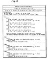
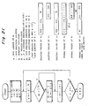
- Fig. 21 is a flowchart showing the calculation of N'.
- the reference symbol n denotes the bit length of N, i the bit position pointer, A the working register, B the N' result register, a 2 i N storage register, Ai the bit position denoted by i of A, and Bi the bit position denoted by i of B, wherein the bit length of the working register A and the 2 i N a is 2n, and the bit length of B is n.
- bit position pointer i data representing the bit length of N is set to n and the value of N is set to the working register A, while the bit position pointer i and the N' result register B are clear.
- the 2 i N storage register is set 2 i N (initial value is 2 0 N).
- the value of the bit position Ai is checked on whether it is equal to 1 or not. if yes, then the bit position pointer i develops its increment. If no, then the bit position Bi is set 1 and a new value of the former value of the working register A plus the value (initial value is 2 0 N) of the 2 i N storage register is set to the working register A; and also the same increment of the bit position pointer i follows.
- bit position pointer i is checked on whether or not it is equal to the bit length of N plus 1. If yes(it differs therefrom), then the similar procedure continues, which will repeat until it reaches the bit length of N plus 1. If no (it equals thereto), the calculation of N' is over. In this way, the final value of the N' result register B provides N'.
- FIG. 22 shows an example of calculating N' and R', each of which involves comparatively short digit number.
- the left bit-shift of N is repeated until the LSB (Least Significant Bit) of the shifted N encounters a first "0" bit (2 3 ) lying in the 2 0 ⁇ N, that is, the left bit-shift is performed three times. This gives 2 3 ⁇ N.
- the 2 0 ⁇ N and 2 3 ⁇ N are added, which provides a first sum 11110001111 as shown in the figure.
- Fig. 13 is a block diagram schematically illustrating the modular arithmetic coprocessor according to the fifth embodiment of the present invention.
- the multiplicand storage register Yi-reg is increased to a plurality of multiplicand storage registers and there is provided a circuit for selecting outputs of the plurality of multiplicand storage registers as compared with the above embodiments. Further, the registers for storing the upper digit output value or the lower digit output value of the high-speed adder Add are provided correspondingly in number to the multiplicand storage registers and there are provided selection circuits for properly selecting output values of the registers.
- registers Yi-reg[0], Yi-reg[1], Yi-reg[2] and Yi-reg[3] are the multiplicand storage registers having the bit length corresponding to the input bit length of the high-speed multiplier/adder Mul/Add and respective outputs of these multiplicand storage registers are connect to the multiplicand selection circuit Yi-sel.
- the multiplicand selection circuit Yi-sel is a selection circuit which selects any one of values in the registers Yi-reg[0], Yi-reg[1], Yi-reg[2] and Yi-reg[3] to supply the selected value to the high-speed multiplier/adder Mul/Add in the subsequent state.
- the selection circuit SelB selects any of contents of R-low and a register RA and is connected to the register RB to supply the selected result to the register RB.
- the register RB is a register for temporarily storing the output of the selection circuit SelB and the output of a register RB is connected to the register RC and Ensel.
- the register RC is a register for temporarily storing the output of the register RB and the output of the register RC is connected to a register RD and the selection circuit Ensel.
- the register RD is a register for temporarily storing the output of the register RC and the output of the register RD is connected to the selection circuit Ensel and the high-speed multiplier/adder Mul/Add.
- the selection circuit Ensel is a selection circuit for selecting any one of contents of the registers RA, RB, RC and RD and supplying the selected result to the arithmetic value memories.
- the underlined address means that the final arithmetic result is stored therein.
- An arithmetic operation is made among a value of the register Xi-reg, a value of the register Yi-reg[0] selected by the selection circuit Yi-sel, a value of the register RD and a value of the register Ai-reg selected by the selection circuit SelA.
- the upper digit R-high of the arithmetic result is stored in the register RA and the lower digit R-low thereof is stored in the arithmetic value memory Wlmem.
- the values of the registers RC and RB are stored in the registers RD and RC, respectively, and the value of the register RA is stored in the register RB selected by the selection circuit SelB.
- the arithmetic operation is made among the value of the register Xi-reg, the value of the register Yi-reg[1] selected by the selection circuit Yi-sel, the value of the register RD and the value of the register RA selected by the selection circuit SelA.
- the upper digit R-high of the arithmetic result is stored in the register RA and the lower digit R-low thereof is stored in the register RB selected by the selection circuit SelB.
- the values of the registers RC and RB are stored in the registers RD and RC, respectively.
- the arithmetic operation is made among the value of the register Xi-reg, the value of the register Yi-reg[2] selected by the selection circuit Yi-sel, the value of the register RD and the value of the register RA selected by the selection circuit SelA.
- the upper digit R-high of the arithmetic result is stored in the register RA and the lower digit R-low thereof is stored in the register RB selected by the selection circuit SelB.
- the values of the registers RC and RB are stored in the registers RD and RC, respectively.
- the arithmetic operation is made among the value of the register Xi-reg, the value of the register Yi-reg[3] selected by the selection circuit Yi-sel, the value of the register RD and the value of the register RA selected by the selection circuit SelA.
- the upper digit R-high of the arithmetic result is stored in the register RA and the lower digit R-low thereof is stored in the register RB selected by the selection circuit SelB.
- the values of the registers RC and RB are stored in the registers RD and RC, respectively.
- step 1 to step 4 the access to the arithmetic value memory is merely made once in step 1. Accordingly, during the remaining period from step 2 to step 4, change of addresses of the arithmetic value memories and precharging can be made to obtain the time for access to the memory.
- the operations performed in the period from step 2 to step 4 are substantially identical and accordingly the arithmetic operation is not complicated.
- the underlined values are the final results of the arithmetic operation.
- the modular arithmetic coprocessor constituted by a small-scale circuit as a whole and having a short operation time.
- Fig. 17 is a block diagram schematically illustrating the sixth embodiment of the present invention.
- the embodiment includes an arithmetic value memory interface circuit and an arithmetic control circuit provided between the coprocessor described above and the external unit.
- the circuit MemIF serves to transmit and receive data between MCU and the arithmetic value memories in the coprocessor.
- the arithmetic value memories store arithmetic data from the outside of the coprocessor prior to the arithmetic operation and send the arithmetic results to the outside of the coprocessor upon completion of the arithmetic operation.
- the arithmetic value memories repeatedly make access to the arithmetic unit dynamically without relation to the outside of the coprocessor. That is, the arithmetic value memories have two kinds of communication protocol.
- the arithmetic value memory interface circuit is constituted to attain the protocol.
- An address signal adrs and a memory control signal Memcon produced by the MCU are inputted to the arithmetic value memory interface MemIF and an address signal Comemad and a memory control signal Comcon are prepared for each arithmetic value memory in the coprocessor in the arithmetic value memory interface MemIF to be supplied to the coprocessor.
- MDbus is a data bus of MCU and CoDbus is a data bus for external interface of the coprocessor.
- arithmetic value memories When the arithmetic value memories are disposed in a single memory space within the MCU, one kind of the adrs signal and the Memcon signal inputted to the arithmetic value memory interface MemIF, and MDbus are provided, while when the arithmetic value memories are disposed in a plurality of memory spaces, a plurality of kinds of inputs are required.
- MDbus and CoDbu are often connected directly, while, for example, when the data length of the arithmetic value memories processed within the coprocessor and the data length of MCU are different, data conversion is made through the arithmetic value memory interface MemIF.
- the arithmetic value memories are operated dynamically for execution of the arithmetic while the coprocessor executes the arithmetic, it is controlled to inhibit access from the MCU. In this manner, the first communication protocol between the arithmetic value memories in the coprocessor and the external unit is realized.
- a memory control signal produced by the timing/control circuit T/C in the coprocessor is inputted to the arithmetic value memory interface MemIF.
- the interface MemIf supplies to the coprocessor the Comemad signal and the Comcon signal processed to cause the arithmetic value memories to transmit and receive data between the arithmetic unit and the arithmetic value memories.
- the second communication protocol between the arithmetic unit and the arithmetic value memories during execution of the arithmetic within the coprocessor is realized.
- the arithmetic control circuit CopCon serves to receive a coprocessor control signal Excon produced by the MCU and supply an arithmetic control signal Sevex (arithmetic mode signal, bit length selection signal and the like in the above embodiments) to the coprocessor.
- the arithmetic operation in the coprocessor is started by supplying the arithmetic mode signal and the clock COPCLK for the coprocessor.
- a timing signal Coend for completion of the arithmetic produced by the timing/control circuit T/C in the coprocessor is received by CopCon and an arithmetic completion monitoring signal Endmoni processed by a latch circuit or the like is supplied to MCU.
- the arithmetic control circuit CopCon can be constituted to be distributed in a local memory area as a peripheral circuit of MCU and make direct access by an instruction of MCU and can be realized by a relatively simple circuit.
- an MCUCLK signal represents a clock for MCU and a COPCLK signal represents a clock for the coprocessor.
- the interface between the external unit (for example, MCU) and the coprocessor can be realized by a relatively small-scale circuit
- the modular arithmetic coprocessor with the external interface or the MCU including the modular arithmetic coprocessor can be constituted and can be realized by LSI.
- the measure for confirming the completion of the arithmetic from the outside of the coprocessor is only the examination of the arithmetic completion monitoring signal Endmoni.
- the time for always monitoring the Endmoni on the side of the MCU in case where the external unit is, for example, the MCU is made relatively long and accordingly the operation performance of the MCU is reduced.
- this embodiment includes an exclusive interrupt control circuit for the completion time of the arithmetic.
- Fig. 18 is a block diagram schematically illustrating the seventh embodiment of the present invention.
- IntCon represents an arithmetic completion interrupt control circuit in which preparation of the interrupt is made by an interrupt setting signal Intset produced by the MCU previously.
- an interrupt processing request signal, an acknowledge signal and a vector control signal necessary for the interrupt are transmitted and received as Intsig between the MCU and the IntCon for each kind of the arithmetic mode set by the CopCon and finally the interrupt preparation is canceled to terminate the interrupt process.
- a single interrupt factor for the arithmetic completion may be set fixedly, while since the coprocessor has a plurality of arithmetic modes, the method of development to the modulo exponentiation arithmetic by the external unit is made easy by performing interrupt for each arithmetic mode and accordingly it is desirable to set a plurality of interrupt factors.
- Intcon can be constituted to be distributed in a local memory area as a peripheral circuit of the MCU similarly to the arithmetic control circuit CopCon and make direct access by an instruction of MCU and can be realized by a relatively simple circuit.
- the modular arithmetic coprocessor with the external interface or the MCU including the modular arithmetic coprocessor having the arithmetic completion interrupt function can be constituted by a relatively small-scale circuit and can be realized by LSI.
- operation of the external unit during execution of the arithmetic may be set to a temporary stop state (hereinafter referred to sleep) in order to suppress a consumption current during execution of the arithmetic in the whole system connected to the external unit.
- sleep a temporary stop state
- the embodiment includes an exclusive external unit sleep control circuit and clock control circuit provided in order to realize the sleep operation.
- Fig. 19 schematically illustrates the eighth embodiment and includes the external unit sleep control circuit and the clock control circuit added to the seventh embodiment.
- Slpcon represents an MCU sleep control circuit, which receives a sleep set signal Slpset from the MCU and produces a sleep signal Slp to supply the sleep signal to the clock control circuit CLKCon.
- the clock control circuit CLKCon usually supplies the clock MCUCLK to the MCU in response to the system clock CLK signal inputted externally, while once the Slp signal is received, the clock control circuit CLKCon serves to stop supply of the clock MCUCLK to the MCU.
- the arithmetic completion timing signal Coend is supplied to the SlpCon to stop supply of the Slp signal to the CLKCon, so that supply of MCUCLK to the MCU from the CLKCon is resumed.
- the sleep control circuit SlpCon may be constituted to have this function.
- the SlpCon can be constituted to be distributed in a local area memory as a peripheral circuit of the MCU similarly to the arithmetic control circuit CopCon and to make direct access by an instruction of the MCU and can be realized by a relatively simple circuit.
- the modular arithmetic coprocessor with the external interface or the MCU including the modular arithmetic coprocessor having the external unit sleep function can be constituted by a relatively small-scale circuit and can be realized by LSI.
- the coprocessor can be used when the high-speed characteristic of the processing time of the cryptograph algorithm for performing a large-scale complicated modular arithmetic is questioned. Accordingly, it is required that the operation time is short even for any frequency of an input clock supplied to the system.
- a frequency multiplied clock control circuit is included to improve the operation speed.
- Fig. 20 is a block diagram schematically illustrating the ninth embodiment, in which the clock control circuit of the eighth embodiment is modified to constitute the frequency multiplied clock control circuit.
- the frequency multiplied clock control circuit may be added to the sixth or seventh embodiment separately.
- CLKCon2 represents the clock control circuit including the frequency multiplied clock control circuit, which is supplied with a signal Ckwset from the MCU as a frequency multiplication setting signal to operate the frequency multiplication function.
- the frequency multiplication function is operated in response to the clock CLK supplied externally, and the circuit thereof is constituted so that the prepared frequency multiplied clock is produced as the clock MCUCLK for the MCU, the clock COPCLK for the coprocessor or both of them.
- the user can make various selection in the system in consideration of trade-off of the consumption current.
- the frequency multiplication function can be canceled by inputting the signal Ckwset as a cancellation signal in the same manner as the setting thereof.
- the frequency multiplied clock control circuit can be constituted to be distributed in a local memory area as a peripheral circuit of the MCU similarly to the arithmetic control CopCon and to make direct access by an instruction of the MCU and can be realized by a relatively simple circuit.
- the modular arithmetic coprocessor with the external interface or the MCU including the modular arithmetic coprocessor having the frequency multiplication function of the system can be constituted by a relatively small-scale circuit to improve the operation processing speed of the whole system and can be realized by LSI.
- the high-speed multiplier/adder Mul/Add shown in the first to fifth embodiments may be constituted by the multiplier and the adder provided separately.
- the high-speed multiplier/adder Mul/Add and the high-speed adder Add shown in the first to fifth embodiments may be constituted integrally.
- the high-speed multiplier/adder Mul/Add and the high-speed adder Add shown in the first to fifth embodiments may be constituted by commercially available ICs.
- the coprocessor shown in the sixth to ninth embodiments is constituted on the basis of the coprocessor shown in the first to fifth embodiments but may be constituted by another coprocessor having the same function as that of the coprocessor shown in the first to fifth embodiment.
- the long-bit-length multiplication algorithm shown in the first to fifth embodiments has been described generally, while another algorithm (for example, BOOTH or the like) capable of being used by the hardware structure used in the description may be constituted by the timing/control circuit.
- another algorithm for example, BOOTH or the like
- the "0" detection circuit ZeroC is used to reduce the arithmetic value memories as the primary object, while the ZeroC can be used to control the sequence so that, for example, when contents of the multiplier or the multiplicand of the unit of multiplication, the arithmetic operation is omitted and the value on the way of the arithmetic operation is set to 0 to proceed to the next operation to thereby reduced the operation time.
- the number of the multiplicand storage register is increased, while the bit length of the multiplicand storage register is lengthened to increase the size thereof.
- the previously prepared mode signal can be merely supplied to thereby execute the various arithmetic operations.
Landscapes
- Engineering & Computer Science (AREA)
- General Physics & Mathematics (AREA)
- Physics & Mathematics (AREA)
- Theoretical Computer Science (AREA)
- Mathematical Optimization (AREA)
- Mathematical Analysis (AREA)
- Pure & Applied Mathematics (AREA)
- Computational Mathematics (AREA)
- Computing Systems (AREA)
- General Engineering & Computer Science (AREA)
- Mathematical Physics (AREA)
- Complex Calculations (AREA)
- Executing Machine-Instructions (AREA)
Applications Claiming Priority (3)
| Application Number | Priority Date | Filing Date | Title |
|---|---|---|---|
| JP110057/96 | 1996-04-05 | ||
| JP11005796A JP3525209B2 (ja) | 1996-04-05 | 1996-04-05 | べき乗剰余演算回路及びべき乗剰余演算システム及びべき乗剰余演算のための演算方法 |
| JP11005796 | 1996-04-05 |
Publications (2)
| Publication Number | Publication Date |
|---|---|
| EP0801345A1 EP0801345A1 (en) | 1997-10-15 |
| EP0801345B1 true EP0801345B1 (en) | 2002-10-16 |
Family
ID=14526000
Family Applications (1)
| Application Number | Title | Priority Date | Filing Date |
|---|---|---|---|
| EP97105465A Expired - Lifetime EP0801345B1 (en) | 1996-04-05 | 1997-04-02 | Circuit for modulo multiplication and exponentiation arithmetic |
Country Status (5)
| Country | Link |
|---|---|
| US (1) | US5982900A (zh) |
| EP (1) | EP0801345B1 (zh) |
| JP (1) | JP3525209B2 (zh) |
| CN (1) | CN1148643C (zh) |
| DE (1) | DE69716331T2 (zh) |
Families Citing this family (48)
| Publication number | Priority date | Publication date | Assignee | Title |
|---|---|---|---|---|
| US6105005A (en) * | 1997-09-15 | 2000-08-15 | Merrill Lynch & Co., Inc. | System for enhanced financial trading support |
| US6557020B1 (en) * | 1997-12-10 | 2003-04-29 | Seiko Epson Corporation | Information processing system, enciphering/deciphering system, system LSI, and electronic apparatus |
| US7587044B2 (en) | 1998-01-02 | 2009-09-08 | Cryptography Research, Inc. | Differential power analysis method and apparatus |
| DE69930334T2 (de) | 1998-01-28 | 2006-11-09 | Hitachi, Ltd. | IC-Karte ausgerüstet mit einer Verarbeitungsanlage für Elliptische-Kurven-Verschlüsselung |
| EP2031792B1 (en) * | 1998-06-03 | 2013-01-09 | Cryptography Research Inc. | Secure modular exponentiation with leak minimization for smartcards and other cryptosystems |
| IL139935A (en) | 1998-06-03 | 2005-06-19 | Cryptography Res Inc | Des and other cryptographic processes with leak minimization for smartcards and other cryptosystems |
| ATE360866T1 (de) | 1998-07-02 | 2007-05-15 | Cryptography Res Inc | Leckresistente aktualisierung eines indexierten kryptographischen schlüssels |
| US6963644B1 (en) * | 1999-04-07 | 2005-11-08 | Matsushita Electric Industrial Co., Ltd. | Multi-word arithmetic device for faster computation of cryptosystem calculations |
| FR2799851B1 (fr) * | 1999-10-14 | 2002-01-25 | Gemplus Card Int | Procede de contre-mesure dans un composant electronique mettant en oeuvre un algorithme de cryptographie a cle publique de type rsa |
| US6879689B2 (en) * | 2000-05-09 | 2005-04-12 | Verizon Laboratories Inc. | Stream-cipher method and apparatus |
| US7031943B1 (en) | 2000-05-10 | 2006-04-18 | Cisco Technology, Inc. | Digital license agreement |
| US6763365B2 (en) | 2000-12-19 | 2004-07-13 | International Business Machines Corporation | Hardware implementation for modular multiplication using a plurality of almost entirely identical processor elements |
| CA2330166A1 (en) * | 2000-12-29 | 2002-06-29 | Nortel Networks Limited | Data encryption using stateless confusion generators |
| DE10107376A1 (de) * | 2001-02-16 | 2002-08-29 | Infineon Technologies Ag | Verfahren und Vorrichtung zum modularen Multiplizieren und Rechenwerk zum modularen Multiplizieren |
| JP3950638B2 (ja) | 2001-03-05 | 2007-08-01 | 株式会社日立製作所 | 耐タンパーモジュラ演算処理方法 |
| DE10111987A1 (de) * | 2001-03-13 | 2002-09-26 | Infineon Technologies Ag | Verfahren und Vorrichtung zum modularen Multiplizieren |
| US20020184208A1 (en) * | 2001-04-24 | 2002-12-05 | Saul Kato | System and method for dynamically generating content on a portable computing device |
| US7017064B2 (en) * | 2001-05-09 | 2006-03-21 | Mosaid Technologies, Inc. | Calculating apparatus having a plurality of stages |
| US7027597B1 (en) | 2001-09-18 | 2006-04-11 | Cisco Technologies, Inc. | Pre-computation and dual-pass modular arithmetic operation approach to implement encryption protocols efficiently in electronic integrated circuits |
| US7027598B1 (en) | 2001-09-19 | 2006-04-11 | Cisco Technology, Inc. | Residue number system based pre-computation and dual-pass arithmetic modular operation approach to implement encryption protocols efficiently in electronic integrated circuits |
| US7191333B1 (en) | 2001-10-25 | 2007-03-13 | Cisco Technology, Inc. | Method and apparatus for calculating a multiplicative inverse of an element of a prime field |
| US7451326B2 (en) * | 2002-08-26 | 2008-11-11 | Mosaid Technologies, Inc. | Method and apparatus for processing arbitrary key bit length encryption operations with similar efficiencies |
| US7386705B2 (en) | 2002-08-27 | 2008-06-10 | Mosaid Technologies Inc. | Method for allocating processor resources and system for encrypting data |
| US7647277B1 (en) | 2002-10-25 | 2010-01-12 | Time Warner Inc. | Regulating access to content using a multitiered rule base |
| JP2004258141A (ja) | 2003-02-24 | 2004-09-16 | Fujitsu Ltd | モンゴメリ乗算剰余の多倍長演算のための演算装置 |
| US20040250121A1 (en) * | 2003-05-06 | 2004-12-09 | Keith Millar | Assessing security of information technology |
| ATE479142T1 (de) * | 2003-10-14 | 2010-09-15 | Panasonic Corp | Datenumsetzer |
| JP4662802B2 (ja) | 2005-03-30 | 2011-03-30 | 富士通株式会社 | 計算方法、計算装置及びコンピュータプログラム |
| CN100435091C (zh) * | 2006-03-01 | 2008-11-19 | 成都卫士通信息产业股份有限公司 | 大数模幂系统的硬件高基实现方法 |
| US7849125B2 (en) | 2006-07-07 | 2010-12-07 | Via Telecom Co., Ltd | Efficient computation of the modulo operation based on divisor (2n-1) |
| US7870395B2 (en) | 2006-10-20 | 2011-01-11 | International Business Machines Corporation | Load balancing for a system of cryptographic processors |
| US8532288B2 (en) | 2006-12-01 | 2013-09-10 | International Business Machines Corporation | Selectively isolating processor elements into subsets of processor elements |
| US7890559B2 (en) | 2006-12-22 | 2011-02-15 | International Business Machines Corporation | Forward shifting of processor element processing for load balancing |
| US8005210B2 (en) * | 2007-06-30 | 2011-08-23 | Intel Corporation | Modulus scaling for elliptic-curve cryptography |
| JP5097138B2 (ja) * | 2009-01-15 | 2012-12-12 | シャープ株式会社 | モンゴメリ乗算のための演算回路及び暗号回路 |
| JP5407352B2 (ja) * | 2009-01-19 | 2014-02-05 | 富士通株式会社 | 復号処理装置、復号処理プログラム、復号処理方法 |
| EP2564364A1 (en) | 2010-04-30 | 2013-03-06 | Now Technologies (IP) Limited | Content management apparatus |
| US8626811B2 (en) * | 2010-04-30 | 2014-01-07 | Certicom Corp. | Method and apparatus for providing flexible bit-length moduli on a block Montgomery machine |
| WO2012090289A1 (ja) * | 2010-12-27 | 2012-07-05 | 富士通株式会社 | 暗号処理装置および方法 |
| FR2972064B1 (fr) * | 2011-02-25 | 2013-03-15 | Inside Secure | Procede de cryptographie comprenant une operation d'exponentiation |
| EP2523385B1 (en) * | 2011-05-05 | 2017-07-12 | Proton World International N.V. | Method and circuit for cryptographic operation |
| DE102012005427A1 (de) * | 2012-03-16 | 2013-09-19 | Giesecke & Devrient Gmbh | Verfahren und System zur gesicherten Kommunikation zwischen einen RFID-Tag und einem Lesegerät |
| CN107688466B (zh) * | 2016-08-05 | 2020-11-03 | 中科寒武纪科技股份有限公司 | 一种运算装置及其操作方法 |
| FR3076925B1 (fr) | 2018-01-16 | 2020-01-24 | Proton World International N.V. | Fonction cryptographique |
| WO2019191040A1 (en) * | 2018-03-28 | 2019-10-03 | Cryptography Research, Inc. | Using cryptographic blinding for efficient use of montgomery multiplication |
| WO2023141934A1 (en) * | 2022-01-28 | 2023-08-03 | Nvidia Corporation | Efficient masking of secure data in ladder-type cryptographic computations |
| WO2023141933A1 (en) | 2022-01-28 | 2023-08-03 | Nvidia Corporation | Techniques, devices, and instruction set architecture for efficient modular division and inversion |
| CN114840175B (zh) * | 2022-06-30 | 2022-09-13 | 中科声龙科技发展(北京)有限公司 | 一种实现取余运算的装置、方法及运算芯片 |
Family Cites Families (9)
| Publication number | Priority date | Publication date | Assignee | Title |
|---|---|---|---|---|
| US5101431A (en) * | 1990-12-14 | 1992-03-31 | Bell Communications Research, Inc. | Systolic array for modular multiplication |
| IL97413A (en) * | 1991-03-04 | 1995-06-29 | Fortress U & T 2000 Ltd | Microcircuit for the implementation of rsa algorithm and ordinary and modular arithmetic in particular exponentiation with large operands |
| ATE183315T1 (de) * | 1991-09-05 | 1999-08-15 | Canon Kk | Verfahren und gerät zum verschlüsseln und entschlüsseln von kommunikationsdaten |
| IL101623A (en) * | 1992-04-16 | 1997-06-10 | Fortress U & T 2000 Ltd | Digital signature device |
| EP0577000B1 (en) * | 1992-06-29 | 1998-09-02 | THOMSON multimedia | Method for performing public-key cryptography |
| JPH0720778A (ja) * | 1993-07-02 | 1995-01-24 | Fujitsu Ltd | 剰余計算装置、テーブル作成装置および乗算剰余計算装置 |
| DE69434422T2 (de) * | 1993-11-30 | 2006-04-20 | Canon K.K. | Verfahren und Anordnung zur Verschlüsselung/Entschlüsselung auf der Basis des Montgomery-Verfahrens unter Verwendung von effizienter modularer Multiplikation |
| FR2726667B1 (fr) * | 1994-11-08 | 1997-01-17 | Sgs Thomson Microelectronics | Procede de mise en oeuvre de multiplication modulaire selon la methode montgomery |
| US5724279A (en) * | 1995-08-25 | 1998-03-03 | Microsoft Corporation | Computer-implemented method and computer for performing modular reduction |
-
1996
- 1996-04-05 JP JP11005796A patent/JP3525209B2/ja not_active Expired - Fee Related
-
1997
- 1997-04-02 DE DE69716331T patent/DE69716331T2/de not_active Expired - Fee Related
- 1997-04-02 EP EP97105465A patent/EP0801345B1/en not_active Expired - Lifetime
- 1997-04-04 US US08/833,002 patent/US5982900A/en not_active Expired - Fee Related
- 1997-04-07 CN CNB971102899A patent/CN1148643C/zh not_active Expired - Fee Related
Also Published As
| Publication number | Publication date |
|---|---|
| JP3525209B2 (ja) | 2004-05-10 |
| DE69716331T2 (de) | 2003-06-18 |
| DE69716331D1 (de) | 2002-11-21 |
| EP0801345A1 (en) | 1997-10-15 |
| CN1172390A (zh) | 1998-02-04 |
| US5982900A (en) | 1999-11-09 |
| JPH09274560A (ja) | 1997-10-21 |
| CN1148643C (zh) | 2004-05-05 |
Similar Documents
| Publication | Publication Date | Title |
|---|---|---|
| EP0801345B1 (en) | Circuit for modulo multiplication and exponentiation arithmetic | |
| US5742530A (en) | Compact microelectronic device for performing modular multiplication and exponentiation over large numbers | |
| US6182104B1 (en) | Circuit and method of modulo multiplication | |
| US6356636B1 (en) | Circuit and method for fast modular multiplication | |
| EP0947914B1 (en) | Computationally efficient modular multiplication method and apparatus | |
| US5764554A (en) | Method for the implementation of modular reduction according to the Montgomery method | |
| US6397241B1 (en) | Multiplier cell and method of computing | |
| US5745398A (en) | Method for the implementation of modular multiplication according to the Montgomery method | |
| US7831650B2 (en) | Method for modular multiplication | |
| US5210710A (en) | Modulo arithmetic processor chip | |
| JPS61223876A (ja) | 暗号装置と累乗方法 | |
| EP0938790B1 (en) | A method and device for executing a decrypting mechanism through calculating a standardized modular exponentiation for thwarting timing attacks | |
| KR100442218B1 (ko) | 몽고메리의 알고리즘을 이용한 멱승 잉여 연산기 | |
| KR100436814B1 (ko) | 아이씨카드용 알에스에이 암호 연산 장치 | |
| US6917956B2 (en) | Apparatus and method for efficient modular exponentiation | |
| US6662201B1 (en) | Modular arithmetic apparatus and method having high-speed base conversion function | |
| EP1818810B1 (en) | Circuit and method for multiplying long integer values | |
| WO2000038047A1 (en) | Circuit and method of cryptographic multiplication | |
| JP2001188468A (ja) | ガロア体上の元の除算演算方法および除算演算回路 | |
| US20030128842A1 (en) | Modular squaring circuit, modular squaring method, and modular squaring program | |
| Großschädl | A new serial/parallel architecture for a low power modular multiplier | |
| JPH10260818A (ja) | BのC乗のnを法とした剰余を計算する回路 |
Legal Events
| Date | Code | Title | Description |
|---|---|---|---|
| PUAI | Public reference made under article 153(3) epc to a published international application that has entered the european phase |
Free format text: ORIGINAL CODE: 0009012 |
|
| AK | Designated contracting states |
Kind code of ref document: A1 Designated state(s): DE FR GB NL |
|
| 17P | Request for examination filed |
Effective date: 19980305 |
|
| 17Q | First examination report despatched |
Effective date: 20001114 |
|
| GRAG | Despatch of communication of intention to grant |
Free format text: ORIGINAL CODE: EPIDOS AGRA |
|
| RTI1 | Title (correction) |
Free format text: CIRCUIT FOR MODULO MULTIPLICATION AND EXPONENTIATION ARITHMETIC |
|
| GRAG | Despatch of communication of intention to grant |
Free format text: ORIGINAL CODE: EPIDOS AGRA |
|
| GRAH | Despatch of communication of intention to grant a patent |
Free format text: ORIGINAL CODE: EPIDOS IGRA |
|
| GRAH | Despatch of communication of intention to grant a patent |
Free format text: ORIGINAL CODE: EPIDOS IGRA |
|
| GRAA | (expected) grant |
Free format text: ORIGINAL CODE: 0009210 |
|
| AK | Designated contracting states |
Kind code of ref document: B1 Designated state(s): DE FR GB NL |
|
| REG | Reference to a national code |
Ref country code: GB Ref legal event code: FG4D |
|
| REF | Corresponds to: |
Ref document number: 69716331 Country of ref document: DE Date of ref document: 20021121 |
|
| PGFP | Annual fee paid to national office [announced via postgrant information from national office to epo] |
Ref country code: GB Payment date: 20030319 Year of fee payment: 7 |
|
| PGFP | Annual fee paid to national office [announced via postgrant information from national office to epo] |
Ref country code: NL Payment date: 20030416 Year of fee payment: 7 |
|
| PGFP | Annual fee paid to national office [announced via postgrant information from national office to epo] |
Ref country code: FR Payment date: 20030417 Year of fee payment: 7 |
|
| ET | Fr: translation filed | ||
| PGFP | Annual fee paid to national office [announced via postgrant information from national office to epo] |
Ref country code: DE Payment date: 20030627 Year of fee payment: 7 |
|
| PLBE | No opposition filed within time limit |
Free format text: ORIGINAL CODE: 0009261 |
|
| STAA | Information on the status of an ep patent application or granted ep patent |
Free format text: STATUS: NO OPPOSITION FILED WITHIN TIME LIMIT |
|
| 26N | No opposition filed |
Effective date: 20030717 |
|
| PG25 | Lapsed in a contracting state [announced via postgrant information from national office to epo] |
Ref country code: GB Free format text: LAPSE BECAUSE OF NON-PAYMENT OF DUE FEES Effective date: 20040402 |
|
| PG25 | Lapsed in a contracting state [announced via postgrant information from national office to epo] |
Ref country code: NL Free format text: LAPSE BECAUSE OF NON-PAYMENT OF DUE FEES Effective date: 20041101 |
|
| PG25 | Lapsed in a contracting state [announced via postgrant information from national office to epo] |
Ref country code: DE Free format text: LAPSE BECAUSE OF NON-PAYMENT OF DUE FEES Effective date: 20041103 |
|
| GBPC | Gb: european patent ceased through non-payment of renewal fee | ||
| PG25 | Lapsed in a contracting state [announced via postgrant information from national office to epo] |
Ref country code: FR Free format text: LAPSE BECAUSE OF NON-PAYMENT OF DUE FEES Effective date: 20041231 |
|
| NLV4 | Nl: lapsed or anulled due to non-payment of the annual fee |
Effective date: 20041101 |
|
| REG | Reference to a national code |
Ref country code: FR Ref legal event code: ST |