EP0801273B1 - Air-conditioned construction of floor and ceiling - Google Patents
Air-conditioned construction of floor and ceiling Download PDFInfo
- Publication number
- EP0801273B1 EP0801273B1 EP96935448A EP96935448A EP0801273B1 EP 0801273 B1 EP0801273 B1 EP 0801273B1 EP 96935448 A EP96935448 A EP 96935448A EP 96935448 A EP96935448 A EP 96935448A EP 0801273 B1 EP0801273 B1 EP 0801273B1
- Authority
- EP
- European Patent Office
- Prior art keywords
- floor
- ceiling
- water
- main body
- conditioning system
- Prior art date
- Legal status (The legal status is an assumption and is not a legal conclusion. Google has not performed a legal analysis and makes no representation as to the accuracy of the status listed.)
- Expired - Lifetime
Links
- 238000010276 construction Methods 0.000 title abstract description 29
- XLYOFNOQVPJJNP-UHFFFAOYSA-N water Substances O XLYOFNOQVPJJNP-UHFFFAOYSA-N 0.000 claims abstract description 63
- 238000010438 heat treatment Methods 0.000 claims abstract description 58
- 238000001816 cooling Methods 0.000 claims abstract description 23
- 238000004378 air conditioning Methods 0.000 claims description 20
- 239000004570 mortar (masonry) Substances 0.000 claims description 5
- 239000003795 chemical substances by application Substances 0.000 abstract description 12
- 239000010410 layer Substances 0.000 description 39
- 230000001172 regenerating effect Effects 0.000 description 4
- 230000005855 radiation Effects 0.000 description 3
- 150000001875 compounds Chemical class 0.000 description 2
- 230000000694 effects Effects 0.000 description 2
- 230000003760 hair shine Effects 0.000 description 2
- 238000009434 installation Methods 0.000 description 2
- 238000011835 investigation Methods 0.000 description 2
- 239000000463 material Substances 0.000 description 2
- 229920003002 synthetic resin Polymers 0.000 description 2
- 239000000057 synthetic resin Substances 0.000 description 2
- 241001312218 Arisaema triphyllum Species 0.000 description 1
- OKTJSMMVPCPJKN-UHFFFAOYSA-N Carbon Chemical compound [C] OKTJSMMVPCPJKN-UHFFFAOYSA-N 0.000 description 1
- 235000006481 Colocasia esculenta Nutrition 0.000 description 1
- 239000011358 absorbing material Substances 0.000 description 1
- 229910052799 carbon Inorganic materials 0.000 description 1
- 230000001419 dependent effect Effects 0.000 description 1
- 238000005485 electric heating Methods 0.000 description 1
- 230000007613 environmental effect Effects 0.000 description 1
- 238000001704 evaporation Methods 0.000 description 1
- 239000004744 fabric Substances 0.000 description 1
- 239000007788 liquid Substances 0.000 description 1
- 239000002184 metal Substances 0.000 description 1
- 238000000034 method Methods 0.000 description 1
- 230000003287 optical effect Effects 0.000 description 1
- 239000002984 plastic foam Substances 0.000 description 1
- 238000004064 recycling Methods 0.000 description 1
- 239000002356 single layer Substances 0.000 description 1
- 229910001220 stainless steel Inorganic materials 0.000 description 1
- 239000010935 stainless steel Substances 0.000 description 1
- 229920003051 synthetic elastomer Polymers 0.000 description 1
- 239000005061 synthetic rubber Substances 0.000 description 1
- 230000008016 vaporization Effects 0.000 description 1
- 230000002747 voluntary effect Effects 0.000 description 1
Images

Classifications
-
- F—MECHANICAL ENGINEERING; LIGHTING; HEATING; WEAPONS; BLASTING
- F24—HEATING; RANGES; VENTILATING
- F24F—AIR-CONDITIONING; AIR-HUMIDIFICATION; VENTILATION; USE OF AIR CURRENTS FOR SCREENING
- F24F5/00—Air-conditioning systems or apparatus not covered by F24F1/00 or F24F3/00, e.g. using solar heat or combined with household units such as an oven or water heater
- F24F5/0046—Air-conditioning systems or apparatus not covered by F24F1/00 or F24F3/00, e.g. using solar heat or combined with household units such as an oven or water heater using natural energy, e.g. solar energy, energy from the ground
-
- F—MECHANICAL ENGINEERING; LIGHTING; HEATING; WEAPONS; BLASTING
- F24—HEATING; RANGES; VENTILATING
- F24D—DOMESTIC- OR SPACE-HEATING SYSTEMS, e.g. CENTRAL HEATING SYSTEMS; DOMESTIC HOT-WATER SUPPLY SYSTEMS; ELEMENTS OR COMPONENTS THEREFOR
- F24D3/00—Hot-water central heating systems
- F24D3/005—Hot-water central heating systems combined with solar energy
-
- F—MECHANICAL ENGINEERING; LIGHTING; HEATING; WEAPONS; BLASTING
- F24—HEATING; RANGES; VENTILATING
- F24D—DOMESTIC- OR SPACE-HEATING SYSTEMS, e.g. CENTRAL HEATING SYSTEMS; DOMESTIC HOT-WATER SUPPLY SYSTEMS; ELEMENTS OR COMPONENTS THEREFOR
- F24D3/00—Hot-water central heating systems
- F24D3/12—Tube and panel arrangements for ceiling, wall, or underfloor heating
- F24D3/14—Tube and panel arrangements for ceiling, wall, or underfloor heating incorporated in a ceiling, wall or floor
-
- F—MECHANICAL ENGINEERING; LIGHTING; HEATING; WEAPONS; BLASTING
- F24—HEATING; RANGES; VENTILATING
- F24S—SOLAR HEAT COLLECTORS; SOLAR HEAT SYSTEMS
- F24S20/00—Solar heat collectors specially adapted for particular uses or environments
- F24S20/60—Solar heat collectors integrated in fixed constructions, e.g. in buildings
- F24S20/61—Passive solar heat collectors, e.g. operated without external energy source
-
- F—MECHANICAL ENGINEERING; LIGHTING; HEATING; WEAPONS; BLASTING
- F24—HEATING; RANGES; VENTILATING
- F24S—SOLAR HEAT COLLECTORS; SOLAR HEAT SYSTEMS
- F24S20/00—Solar heat collectors specially adapted for particular uses or environments
- F24S20/60—Solar heat collectors integrated in fixed constructions, e.g. in buildings
- F24S20/64—Solar heat collectors integrated in fixed constructions, e.g. in buildings in the form of floor constructions, grounds or roads
-
- F—MECHANICAL ENGINEERING; LIGHTING; HEATING; WEAPONS; BLASTING
- F24—HEATING; RANGES; VENTILATING
- F24S—SOLAR HEAT COLLECTORS; SOLAR HEAT SYSTEMS
- F24S60/00—Arrangements for storing heat collected by solar heat collectors
- F24S60/30—Arrangements for storing heat collected by solar heat collectors storing heat in liquids
-
- F—MECHANICAL ENGINEERING; LIGHTING; HEATING; WEAPONS; BLASTING
- F24—HEATING; RANGES; VENTILATING
- F24D—DOMESTIC- OR SPACE-HEATING SYSTEMS, e.g. CENTRAL HEATING SYSTEMS; DOMESTIC HOT-WATER SUPPLY SYSTEMS; ELEMENTS OR COMPONENTS THEREFOR
- F24D3/00—Hot-water central heating systems
- F24D3/12—Tube and panel arrangements for ceiling, wall, or underfloor heating
-
- F—MECHANICAL ENGINEERING; LIGHTING; HEATING; WEAPONS; BLASTING
- F24—HEATING; RANGES; VENTILATING
- F24F—AIR-CONDITIONING; AIR-HUMIDIFICATION; VENTILATION; USE OF AIR CURRENTS FOR SCREENING
- F24F5/00—Air-conditioning systems or apparatus not covered by F24F1/00 or F24F3/00, e.g. using solar heat or combined with household units such as an oven or water heater
- F24F5/0046—Air-conditioning systems or apparatus not covered by F24F1/00 or F24F3/00, e.g. using solar heat or combined with household units such as an oven or water heater using natural energy, e.g. solar energy, energy from the ground
- F24F2005/0064—Air-conditioning systems or apparatus not covered by F24F1/00 or F24F3/00, e.g. using solar heat or combined with household units such as an oven or water heater using natural energy, e.g. solar energy, energy from the ground using solar energy
-
- Y—GENERAL TAGGING OF NEW TECHNOLOGICAL DEVELOPMENTS; GENERAL TAGGING OF CROSS-SECTIONAL TECHNOLOGIES SPANNING OVER SEVERAL SECTIONS OF THE IPC; TECHNICAL SUBJECTS COVERED BY FORMER USPC CROSS-REFERENCE ART COLLECTIONS [XRACs] AND DIGESTS
- Y02—TECHNOLOGIES OR APPLICATIONS FOR MITIGATION OR ADAPTATION AGAINST CLIMATE CHANGE
- Y02B—CLIMATE CHANGE MITIGATION TECHNOLOGIES RELATED TO BUILDINGS, e.g. HOUSING, HOUSE APPLIANCES OR RELATED END-USER APPLICATIONS
- Y02B10/00—Integration of renewable energy sources in buildings
- Y02B10/20—Solar thermal
-
- Y—GENERAL TAGGING OF NEW TECHNOLOGICAL DEVELOPMENTS; GENERAL TAGGING OF CROSS-SECTIONAL TECHNOLOGIES SPANNING OVER SEVERAL SECTIONS OF THE IPC; TECHNICAL SUBJECTS COVERED BY FORMER USPC CROSS-REFERENCE ART COLLECTIONS [XRACs] AND DIGESTS
- Y02—TECHNOLOGIES OR APPLICATIONS FOR MITIGATION OR ADAPTATION AGAINST CLIMATE CHANGE
- Y02B—CLIMATE CHANGE MITIGATION TECHNOLOGIES RELATED TO BUILDINGS, e.g. HOUSING, HOUSE APPLIANCES OR RELATED END-USER APPLICATIONS
- Y02B30/00—Energy efficient heating, ventilation or air conditioning [HVAC]
-
- Y—GENERAL TAGGING OF NEW TECHNOLOGICAL DEVELOPMENTS; GENERAL TAGGING OF CROSS-SECTIONAL TECHNOLOGIES SPANNING OVER SEVERAL SECTIONS OF THE IPC; TECHNICAL SUBJECTS COVERED BY FORMER USPC CROSS-REFERENCE ART COLLECTIONS [XRACs] AND DIGESTS
- Y02—TECHNOLOGIES OR APPLICATIONS FOR MITIGATION OR ADAPTATION AGAINST CLIMATE CHANGE
- Y02E—REDUCTION OF GREENHOUSE GAS [GHG] EMISSIONS, RELATED TO ENERGY GENERATION, TRANSMISSION OR DISTRIBUTION
- Y02E10/00—Energy generation through renewable energy sources
- Y02E10/40—Solar thermal energy, e.g. solar towers
-
- Y—GENERAL TAGGING OF NEW TECHNOLOGICAL DEVELOPMENTS; GENERAL TAGGING OF CROSS-SECTIONAL TECHNOLOGIES SPANNING OVER SEVERAL SECTIONS OF THE IPC; TECHNICAL SUBJECTS COVERED BY FORMER USPC CROSS-REFERENCE ART COLLECTIONS [XRACs] AND DIGESTS
- Y02—TECHNOLOGIES OR APPLICATIONS FOR MITIGATION OR ADAPTATION AGAINST CLIMATE CHANGE
- Y02E—REDUCTION OF GREENHOUSE GAS [GHG] EMISSIONS, RELATED TO ENERGY GENERATION, TRANSMISSION OR DISTRIBUTION
- Y02E10/00—Energy generation through renewable energy sources
- Y02E10/40—Solar thermal energy, e.g. solar towers
- Y02E10/44—Heat exchange systems
Definitions
- This invention relates to a floor and a ceiling heating system to be used in winter season and in intense cold area, and also relates to a floor and a ceiling cooling system to be used in summer season and in warm area. More in detail this invention relates to a construction of air-conditioning system built in floor and ceiling, being characteristic of not only using water which is gentle to a human body and environment as a filling up agent, but also using low cost energy such as solar energy, outside air temperature and evaporating energy for heating or cooling.
- a floor heating system is becoming to attract a people's attention by following reasons. That is, since a room can be heated homogeneously by conductive heat or radiation heat from a floor, this system is recognized to have features to be gentle to a human body, not to pollute surrounding air and to be noiseless. Further, the room can be effectively and widely used because the floor itself is a heating system.
- the conventional floor heating system is not only avoided from the expensive equipment investigation, but also has a problem in a comfortableness. That is, since this system uses a panel heater attached to the wooden structure, a heat capacity is low and a sensible temperature is easily changed by a change of surrounded atmosphere. Further, in general, regenerative agents used in a panel heater is not only very expensive but also has an environmental problem when wasted because they are chemically synthesized compounds. To dissolve said problem, the applicant of this invention has already disclosed a floor heating system which uses water as a regenerative agent in Japanese patent application JP-5135178 (Japanese patent laid open publication JP-6323554, however, electric energy is mainly used for a heating means in this invention.
- a floor heating structure which comprises two layers spaced from each other and water-filled containers located between the two layers.
- the water in the containers can be heated by a heat source disposed on a side or the bottom of the containers. In that heating system only expensive energy can be used.
- a room heating construction which comprises an external collector in order to collect solar heat energy in the floor heating system for heating the room.
- the heating energy is past from the collector to the floor heating system by a heat exchanger.
- This system has the disadvantage that many components are necessary which increases the cost of the system.
- this heating system requires extensive installations and the external collector deteriorates the optical appearance of the building the heating system is built in.
- the air conditioning system of claim 1 comprises an intermediate layer between a surface board and a supporting layer, said intermediate layer being divided into plural spaces by dividing frames which support and divide the intermediate layer, containers filled up by water being set into each said plural spaces and forming a floor or ceiling main body, the containers further comprising sun-light receiving sections which receive sun-light or outside temperature receiving sections which receive outside temperature.
- a concrete or a mortar base layer is constructed under the surface board the containers filled up by water being embedded in said concrete or mortar base layer.
- a heating part can be located below the main body and can be partial or whole part of the sun-light receiving section, and thus dissolve above mentioned problem.
- the heating part which is located below the main body can be provided together with another heating means.
- a heat conductive controlling layer having lower heat conductivity can be provided to the upper surface of water contained in a container almost horizontally.
- the air conditioning system of the present invention can comprise furthermore a cooling part which is located above the main body and is provided to partial or whole part of the outside air temperature receiving section, and thus dissolve above mentioned problems.
- One object of the present invention is to provide an air-conditioned construction using water as a regenerative agent, which is gentle to a human body and environment, comfortable, safe and low price. That is, the present invention is characterised by using water as a regenerative agent instead of expensive chemically synthesized compounds, and by using solar energy, outside air temperature or evaporative energy as a heat source, further by circulating water as a regenerated agent naturally by convection caused by heating of a heating part located lower position of the system without using a special energy for the circulation of water.
- the action of this invention is explained as follows, that is, by using water as a filling up agent, since whole water in container is heated homogeneously by convection action of water when heated, temperature of whole surface floor raises to the same temperature. And, the operating cost is not necessary because it uses solar energy as an energy source, additionally, to the sun-light receiving section a heating part located below the floor or ceiling main body is joined so as to the heated water ascend to the upper position by convection and warm up whole surface of the floor or the ceiling. Further, by providing another heating means as an annex to the sun-light receiving section, the effect of it is still more enlarged.
- period for heat radiation can be extended and the floor can be maintained at comfortable temperature range for longer period, and is possible to maintain the floor in a heating state for a long period.
- This system is an air-cooling system characterizing by using outside air temperature or evaporative energy, it does not cost so much, in addition, by attaching cooling part located above the floor or ceiling main body to the outside air temperature receiving section, cooled water goes down to the lower position by the convection of water and cools down whole surface of the floor or the ceiling.
- the present invention relates to a construction of a floor 1 and ceiling 2 heating system to be used in winter season and in the intense cold area, and more in detail relates to a construction of central heating system which is built in a floor 1 and a ceiling 2 and uses water which is gentle to a human body and an environment as a filling up liquid and which further uses solar energy which does not cost.
- the construction of this invention is characterized by forming an intermediate layer 13 between a surface board 11 and a supporting layer 12, said intermediate layer 13 is divided into plural spaces 15 by dividing frames 14 which support and divide the intermediate layer, containers 16 filled up by water are set into said plural spaces 15 and form a floor or ceiling main body 17, additionally sunlight receiving sections 18 which receive sunlight are attached to some of said containers 16.
- heating parts 18a 28a which are located below the floor main body 17 or the ceiling main body 27 can be provided to the partial or whole part of said sun-light receiving sections 18, 28.
- the present invention also relates to a construction of floor and ceiling cooling system to be used in summer season and in warm area, and more in detail relates to a construction of air-conditioning system which is built in a floor 1 or a ceiling 2 and uses water as filling up agent which is gentle to a human body and environment and cheap, and which further uses outside air temperature or evaporative energy which does not cost much.
- the construction of this invention is characterized by forming an intermediate layer 13, 23 between a surface board 11, 21 and a supporting layer 12, 22, said intermediate layer 13, 23 is divided into plural spaces 15, 25 by dividing frames 14, 24 which support and divide the intermediate layer, further containers 16, 26 filled up by water are set into said plural spaces 15, 25 and form a floor or ceiling main body 17, 27, additionally an outside air temperature receiving section 19, 29 which receives outside air temperature is provided to some of said containers 16, 26. Additionally cooling parts 19a, 29a which are located above said floor main body 17 or ceiling main body 27 are provided to the partial or whole part of said outside air temperature receiving section 28.
- a woody surface floor board 11, an abiabator and a bottom supporting layer 12 such as wire net is constructed on a base of building, and an intermediate layer 13 which has a voluntary height is formed between said surface floor board 11 and said bottom supporting layer 12.
- an intermediate layer 13 which has a voluntary height is formed between said surface floor board 11 and said bottom supporting layer 12.
- containers 16 are set into said plural spaces 15.
- a flexible container made of single layer or complex layer of synthetic resin, synthetic rubber or non-woven cloth, or a rigid container made of metal such as stainless steel or hard type synthetic resin can be preferably used, and water is filled up into said containers 16.
- sun-light receiving sections 18 which receive sun-light S are attached to some of said containers 16.
- said sun-light receiving sections 18 itself can be a floor which is designed to receive sun-light S actively such as sun room, or can be placed at windowside where always sun-light shines, further, it can be constructed at the outside position where sun always shines making a hole through an outer wall of the building.
- sun-light receiving section 18 can be covered by a heat accumulator which absorbs solar energy efficiently and heat the sun-light receiving sections effectively. Additionally, in a night time, to prevent the cooling down of temperature, it is possible to cover it by an adiabator.
- the above mentioned construction of the floor heating system may also be built in a ceiling instead of a floor.
- An intermediate layer 23 is formed between a surface ceiling board 21 and upper supporting layer 22, said intermediate layer 23 is divided into plural spaces 25 by dividing frames 24 which support and divide the layer, containers 26 filled up by water are set into said plural spaces 25 and form a ceiling main body 27, and sun-light receiving sections 28 are similarly provided.
- heating parts 18a and 28a which are located below the floor main body 17 or ceiling main body 27 are provided to the partial or whole part of said sun-light receiving sections 18 and 28.
- heating parts 18a and 28a which are located below the floor main body 17 or ceiling main body 27
- warm water which is heated in the sun-light receiving sections 18 and 28 ascend to the upper position by natural convection and is extended to the whole floor main body 17 or the ceiling main body 27.
- cool water flows back to the heating parts 18a and 28a which is located below the floor main body 17 or ceiling main body 27 and heated in the sun-light receiving sections 18 and 28 and ascend again to the upper position by natural convection. This circulation is repeated, thus the heating can be carried out effectively.
- heating parts 18a and 28a After sunset, the temperature of heating parts 18a and 28a become lower than that of floor main body 17 or ceiling main body 27, however, water of lower temperature remaining in the heating parts 18a and 28a located below the floor main body 17 or ceiling main body 27 remains there without circulating by convection. Therefore, it is possible to maintain the warm temperature of floor 1 or ceiling 2 for many hours.
- a heat conductive controlling layer 7 to the upper surface of water contained in a container 16 almost horizontally (shown in figure 2b).
- a water passable package in which active carbon or arum root paste is filled up a high water absorbing material used as the material for a paper diaper or a gelled material by adding water can be used, and the object of it is to control the energy conduction to the upper region by reducing the heat conduction lower than that of water.
- water contained in said heat conductive controlling layer 7 is not influenced by convection of water, and heat energy is received from the contacted surface of water by means of heat conduction.
- Said heat conductive controlling layer 7 has a function to control the heat energy conduction, however, heat energy is conducted slowly at the surface between the heat conductive controlling layer 7 and water which exists above. That is, even if the temperature of the water below the heat conductive controlling layer 7 is set up at high temperature, the water above the heat conductive controlling layer 7 can maintain comfortable temperature without largely influenced by the temperature of the water below, and the heating effect can be maintained for many hours after the heat supply is shuttered.
- An outside air temperature receiving section 19 is attached to some of containers 16. Said outside air temperature receiving section 19 is located at northern wall of building where is always shaded from sun-light, further it is possible to cool it down using vaporizing heat of water by sprinkling water over the surface.
- the ceiling main body 27 of ceiling 2 cooling system is almost same to the construction of the ceiling 2 heating system, further the outside air temperature receiving section 29 is almost similar to the construction of the cooling system in figure 4.
- cooling parts 19a, 29a which are located above the floor main body 17 or ceiling main body 27 are provided to the partial or whole part of said outside air temperature receiving sections 19, 29.
- This invention relates to a construction of the floor 1 and ceiling 2 cooling and heating system and covers from small scale construction for an individual house to large scale construction for buildings, such as school, kinder-garden or hospital. Since water which is cheap and can be easily procured is used as the filling up agent, it is possible to be procured at the construction spot without a transportation cost, further, when the house or the building is pulled down, contained water can be wasted without hurting a human body or an environment, and even if it is used by recycling it is not deteriorated by repeating uses.
- the filling up agent since water is used as the filling up agent, partially heated or cooled water at the sun-light receiving section or outside air temperature receiving section is diffused by convection and the temperature of water becomes uniform, and the uniform temperature is conducted to a surface floor board or a surface ceiling board, and so the uniform temperature is diffused to the whole room. Further, the price of water used as filling up agent is relatively cheap, additionally, in a case of throwing away or in a case of accident of leaking, water does not affect a human body and an environment. Thus, the air-conditioning system built in a floor and a ceiling of this invention can be said to be gentle to a human body and an environment, additionally, an operating cost is not needed because natural energy is practically used. Namely, the present invention can be said as an epoch-making and an useful invention.
Landscapes
- Engineering & Computer Science (AREA)
- General Engineering & Computer Science (AREA)
- Chemical & Material Sciences (AREA)
- Mechanical Engineering (AREA)
- Combustion & Propulsion (AREA)
- Life Sciences & Earth Sciences (AREA)
- Thermal Sciences (AREA)
- Sustainable Energy (AREA)
- Sustainable Development (AREA)
- Physics & Mathematics (AREA)
- Building Environments (AREA)
- Central Heating Systems (AREA)
- Floor Finish (AREA)
- Central Air Conditioning (AREA)
- Steam Or Hot-Water Central Heating Systems (AREA)
Abstract
Description
- This invention relates to a floor and a ceiling heating system to be used in winter season and in intense cold area, and also relates to a floor and a ceiling cooling system to be used in summer season and in warm area. More in detail this invention relates to a construction of air-conditioning system built in floor and ceiling, being characteristic of not only using water which is gentle to a human body and environment as a filling up agent, but also using low cost energy such as solar energy, outside air temperature and evaporating energy for heating or cooling.
- Recently, a floor heating system is becoming to attract a people's attention by following reasons. That is, since a room can be heated homogeneously by conductive heat or radiation heat from a floor, this system is recognized to have features to be gentle to a human body, not to pollute surrounding air and to be noiseless. Further, the room can be effectively and widely used because the floor itself is a heating system.
- Up to the present time, various kinds of this floor heating system have been developed and actually carried out in various ways. These developed systems has a constructional feature that provide under a wooden floor a panel of electric heater having almost same surface area as the wooden floor and being electrically connected to the commercial electric power source, or pipes in which hot water flows, further provide an abiabator layer and a bottom layer below.
- Although a ceiling heating system is popular in northern part of Europe but is not popular in Japan, and only a method to set up an air conditioner or an electric heating panel which uses a radiation heat closely to a ceiling are practically used.
- Further, an equipment investigation for a cooling system which uses a floor and a ceiling is remarkably expensive, and generally it could not become so popular at the view point of high initial cost.
- The conventional floor heating system is not only avoided from the expensive equipment investigation, but also has a problem in a comfortableness. That is, since this system uses a panel heater attached to the wooden structure, a heat capacity is low and a sensible temperature is easily changed by a change of surrounded atmosphere. Further, in general, regenerative agents used in a panel heater is not only very expensive but also has an environmental problem when wasted because they are chemically synthesized compounds. To dissolve said problem, the applicant of this invention has already disclosed a floor heating system which uses water as a regenerative agent in Japanese patent application JP-5135178 (Japanese patent laid open publication JP-6323554, however, electric energy is mainly used for a heating means in this invention.
- In the afore-mentioned patent document JP 6323554 a floor heating structure is disclosed which comprises two layers spaced from each other and water-filled containers located between the two layers. The water in the containers can be heated by a heat source disposed on a side or the bottom of the containers. In that heating system only expensive energy can be used.
- Furthermore, from the Japanese patent JP 58129118 a room heating construction is known which comprises an external collector in order to collect solar heat energy in the floor heating system for heating the room. The heating energy is past from the collector to the floor heating system by a heat exchanger. This system has the disadvantage that many components are necessary which increases the cost of the system. Furthermore, this heating system requires extensive installations and the external collector deteriorates the optical appearance of the building the heating system is built in.
- It is an object of the present invention to provide a cheap room heating and room cooling system which can use cheap energy and does not require extensive installations.
- According to the present invention, this object is achieved by an air conditioning system as defined in
claim 1. The dependent claims define advantages and preferred embodiments of the present invention. - The inventors of this invention have conduced intensive studies to dissolve above mentioned problems which conventional floor heating systems have, and developed following floor heating systems. That is, the air conditioning system of
claim 1 comprises an intermediate layer between a surface board and a supporting layer, said intermediate layer being divided into plural spaces by dividing frames which support and divide the intermediate layer, containers filled up by water being set into each said plural spaces and forming a floor or ceiling main body, the containers further comprising sun-light receiving sections which receive sun-light or outside temperature receiving sections which receive outside temperature. - In the embodiment of the present invention of
claim 2, a concrete or a mortar base layer is constructed under the surface board the containers filled up by water being embedded in said concrete or mortar base layer. - Further, in the air conditioning system a heating part can be located below the main body and can be partial or whole part of the sun-light receiving section, and thus dissolve above mentioned problem.
- The heating part which is located below the main body can be provided together with another heating means.
- A heat conductive controlling layer having lower heat conductivity can be provided to the upper surface of water contained in a container almost horizontally.
- The air conditioning system of the present invention can comprise furthermore a cooling part which is located above the main body and is provided to partial or whole part of the outside air temperature receiving section, and thus dissolve above mentioned problems.
- One object of the present invention is to provide an air-conditioned construction using water as a regenerative agent, which is gentle to a human body and environment, comfortable, safe and low price. That is, the present invention is characterised by using water as a regenerative agent instead of expensive chemically synthesized compounds, and by using solar energy, outside air temperature or evaporative energy as a heat source, further by circulating water as a regenerated agent naturally by convection caused by heating of a heating part located lower position of the system without using a special energy for the circulation of water.
- The action of this invention is explained as follows, that is, by using water as a filling up agent, since whole water in container is heated homogeneously by convection action of water when heated, temperature of whole surface floor raises to the same temperature. And, the operating cost is not necessary because it uses solar energy as an energy source, additionally, to the sun-light receiving section a heating part located below the floor or ceiling main body is joined so as to the heated water ascend to the upper position by convection and warm up whole surface of the floor or the ceiling. Further, by providing another heating means as an annex to the sun-light receiving section, the effect of it is still more enlarged.
- Still further, when a heat conductivity controlling layer is set up, period for heat radiation can be extended and the floor can be maintained at comfortable temperature range for longer period, and is possible to maintain the floor in a heating state for a long period.
- This system is an air-cooling system characterizing by using outside air temperature or evaporative energy, it does not cost so much, in addition, by attaching cooling part located above the floor or ceiling main body to the outside air temperature receiving section, cooled water goes down to the lower position by the convection of water and cools down whole surface of the floor or the ceiling.
- Air-conditioning constructions of this invention which have accomplished the above mentioned objects are illustrated by the attached drawings of some examples.
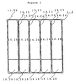
- Figure 1 is a schematic plan view illustrating an example of an air-conditioning construction for a floor or a ceiling of this invention,
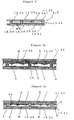
- Figure 2 is a schematic sectional view illustrating the example of an air-conditioning construction for a floor or a ceiling of this invention,
- Figure 2a and figure 2b are schematic sectional views illustrating other examples,
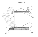
- Figure 3 is a schematic view illustrating the example of an air-conditioning construction installed on a floor and a ceiling,
- Figure 4 is a schematic view illustrating further example of an air-conditioning construction of this invention,
- Figure 5 is a schematic view illustrating an example of a heating system of the present invention equipped with another heating means, and
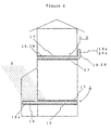
- Figure 6 is a sectional view of a cooling system of the present invention.
-
- The present invention relates to a construction of a
floor 1 andceiling 2 heating system to be used in winter season and in the intense cold area, and more in detail relates to a construction of central heating system which is built in afloor 1 and aceiling 2 and uses water which is gentle to a human body and an environment as a filling up liquid and which further uses solar energy which does not cost. And, the construction of this invention is characterized by forming an intermediate layer 13 between a surface board 11 and a supporting layer 12, said intermediate layer 13 is divided into plural spaces 15 by dividing frames 14 which support and divide the intermediate layer,containers 16 filled up by water are set into said plural spaces 15 and form a floor or ceilingmain body 17, additionallysunlight receiving sections 18 which receive sunlight are attached to some of saidcontainers 16. Additionally, heating parts 18a 28a which are located below the floormain body 17 or the ceilingmain body 27 can be provided to the partial or whole part of said sun-light receiving sections - To the containers, it is possible to provide another heating means 6 together with said sun-
light receiving section 28, and in a structure of floor constructing a concrete or a mortar base layer 2A under the surface floor board, it is possible to embedplural containers 16 in which water is filled up and to provide a heat source to each containers. Further, it is possible to set up a heat conductivity controllinglayer 7 which has lower heat conductivity to the upper end of water contained in a container almost horizontally. - The present invention also relates to a construction of floor and ceiling cooling system to be used in summer season and in warm area, and more in detail relates to a construction of air-conditioning system which is built in a
floor 1 or aceiling 2 and uses water as filling up agent which is gentle to a human body and environment and cheap, and which further uses outside air temperature or evaporative energy which does not cost much. And, the construction of this invention is characterized by forming an intermediate layer 13, 23 between a surface board 11, 21 and a supportinglayer 12, 22, said intermediate layer 13, 23 is divided into plural spaces 15, 25 by dividing frames 14, 24 which support and divide the intermediate layer,further containers main body temperature receiving section containers main body 17 or ceilingmain body 27 are provided to the partial or whole part of said outside airtemperature receiving section 28. - In case of the construction of a cooling and heating system of a
floor 1 described inclaim 1 of this invention, as illustrated by figure 1 and 2, a woody surface floor board 11, an abiabator and a bottom supporting layer 12 such as wire net is constructed on a base of building, and an intermediate layer 13 which has a voluntary height is formed between said surface floor board 11 and said bottom supporting layer 12. By dividing and supporting said intermediate layer 13 with dividing frames 14, plural spaces 15 in whichcontainers 16 can be set are formed, and the size of spaces 15 can be set up voluntarily, further, an abiabator layer of plastic foam or felt under the surface floor board 11 can be also voluntarily prepared. - Then
containers 16 are set into said plural spaces 15. As thecontainer 16, a flexible container made of single layer or complex layer of synthetic resin, synthetic rubber or non-woven cloth, or a rigid container made of metal such as stainless steel or hard type synthetic resin can be preferably used, and water is filled up into saidcontainers 16. - The sun-light receiving
sections 18 which receive sun-light S are attached to some of saidcontainers 16. As illustrated in the first floor of figure 4, said sun-light receivingsections 18 itself can be a floor which is designed to receive sun-light S actively such as sun room, or can be placed at windowside where always sun-light shines, further, it can be constructed at the outside position where sun always shines making a hole through an outer wall of the building. - Further, upper surface of the sun-
light receiving section 18 can be covered by a heat accumulator which absorbs solar energy efficiently and heat the sun-light receiving sections effectively. Additionally, in a night time, to prevent the cooling down of temperature, it is possible to cover it by an adiabator. - To the bottom or side surface of the
containers 16, it is possible to provide another heating means which heat the contained water by other kinds of energy, such as sheet type electric heater, heat accumulating pipe placed on a roof, hot air generator or water heater. Thus the energy for heating can be effectively obtained by using said subsidiary heating means together with the solar energy. - The above mentioned construction of the floor heating system may also be built in a ceiling instead of a floor. An intermediate layer 23 is formed between a surface ceiling board 21 and upper supporting
layer 22, said intermediate layer 23 is divided into plural spaces 25 by dividing frames 24 which support and divide the layer,containers 26 filled up by water are set into said plural spaces 25 and form a ceilingmain body 27, and sun-light receiving sections 28 are similarly provided. - As illustrated by
floor 1 andceiling 2 of the first floor in figure 3, heating parts 18a and 28a which are located below the floormain body 17 or ceilingmain body 27 are provided to the partial or whole part of said sun-light receiving sections - That is, by joining heating parts 18a and 28a which are located below the floor
main body 17 or ceilingmain body 27, warm water which is heated in the sun-light receiving sections main body 17 or the ceilingmain body 27. On the contrary, cool water flows back to the heating parts 18a and 28a which is located below the floormain body 17 or ceilingmain body 27 and heated in the sun-light receiving sections - After sunset, the temperature of heating parts 18a and 28a become lower than that of floor
main body 17 or ceilingmain body 27, however, water of lower temperature remaining in the heating parts 18a and 28a located below the floormain body 17 or ceilingmain body 27 remains there without circulating by convection. Therefore, it is possible to maintain the warm temperature offloor 1 orceiling 2 for many hours. - If it is necessary to set up the temperature of the floor heating system to a higher temperature effectively, it is possible to set up a heat
conductive controlling layer 7 to the upper surface of water contained in acontainer 16 almost horizontally (shown in figure 2b). As the said heat conductive controllinglayer 7, a water passable package in which active carbon or arum root paste is filled up, a high water absorbing material used as the material for a paper diaper or a gelled material by adding water can be used, and the object of it is to control the energy conduction to the upper region by reducing the heat conduction lower than that of water. - In this case; water contained in said heat conductive controlling
layer 7 is not influenced by convection of water, and heat energy is received from the contacted surface of water by means of heat conduction. Said heat conductive controllinglayer 7 has a function to control the heat energy conduction, however, heat energy is conducted slowly at the surface between the heat conductive controllinglayer 7 and water which exists above. That is, even if the temperature of the water below the heat conductive controllinglayer 7 is set up at high temperature, the water above the heat conductive controllinglayer 7 can maintain comfortable temperature without largely influenced by the temperature of the water below, and the heating effect can be maintained for many hours after the heat supply is shuttered. - When the temperature of floor surface becomes higher by influence of sun-light or a foot-warmer than that of contained water, heat energy is stored in water, further the temperature of whole unit in which one
container 16 is set is uniformly warmed up, and partial high temperature can be avoided. - Since the floor
main body 17 offloor 1 cooling system is almost same to the construction offloor 1 heating system, the detailed construction of it is not illustrated here. An outside airtemperature receiving section 19 is attached to some ofcontainers 16. Said outside airtemperature receiving section 19 is located at northern wall of building where is always shaded from sun-light, further it is possible to cool it down using vaporizing heat of water by sprinkling water over the surface. - The ceiling
main body 27 ofceiling 2 cooling system is almost same to the construction of theceiling 2 heating system, further the outside airtemperature receiving section 29 is almost similar to the construction of the cooling system in figure 4. - Additionally, in the construction of
floor 1 andceiling 2 cooling system, as illustrated byfloor 1 of the second floor orceiling 2 of the first floor of figure 4, cooling parts 19a, 29a which are located above the floormain body 17 or ceilingmain body 27 are provided to the partial or whole part of said outside airtemperature receiving sections - That is, by joining heating parts 19a and 29a located above the floor
main body 17 or the ceilingmain body 27, chilled water cooled down by outside air temperature descends to the lower position by natural convection and is extended to the whole floormain body 17 or to the whole ceilingmain body 27. On the contrary, warm water remains at the cooling parts 19a and 29a located above the floormain body 17 or the ceilingmain body 27 and chilled by the out side temperature and descend again to the lower position by natural convection. This circulation is repeated, thus the cooling can be carried out effectively. - That is, the important point of the air conditioning construction of
floor 1 andceiling 2 is'to perform an effective cooling and heating using skillfully convection of water, heat energy stored in water contained in acontainer - This invention relates to a construction of the
floor 1 andceiling 2 cooling and heating system and covers from small scale construction for an individual house to large scale construction for buildings, such as school, kinder-garden or hospital. Since water which is cheap and can be easily procured is used as the filling up agent, it is possible to be procured at the construction spot without a transportation cost, further, when the house or the building is pulled down, contained water can be wasted without hurting a human body or an environment, and even if it is used by recycling it is not deteriorated by repeating uses. - Further in this invention, since sun-light energy and outside air temperature is practically used as an energy source, the equipment is safe and can operate without operating cost.
- As above mentioned, since water is used as the filling up agent, partially heated or cooled water at the sun-light receiving section or outside air temperature receiving section is diffused by convection and the temperature of water becomes uniform, and the uniform temperature is conducted to a surface floor board or a surface ceiling board, and so the uniform temperature is diffused to the whole room. Further, the price of water used as filling up agent is relatively cheap, additionally, in a case of throwing away or in a case of accident of leaking, water does not affect a human body and an environment. Thus, the air-conditioning system built in a floor and a ceiling of this invention can be said to be gentle to a human body and an environment, additionally, an operating cost is not needed because natural energy is practically used. Namely, the present invention can be said as an epoch-making and an useful invention.
Claims (7)
- Air conditioning system which is built in a floor or ceiling of a room comprising:an intermediate layer (13, 23) between a surface board (11, 22) and a supporting layer (12, 21), said intermediate layer (13, 23) being divided into plural spaces (15, 25) by dividing frames (14, 24) which support and divide the intermediate layer (13, 23),containers (16, 26) filled up by water being set into said plural spaces (15, 25) and forming a floor or ceiling main body (17, 27), characterized in that said container further comprise sun-light receiving sections (18, 28) which receive sun-light or outside temperature receiving sections (19, 29) which receive outside temperature.
- Air conditioning system of claim 1, wherein a concrete or a mortar base layer is constructed under the surface board (11, 22) the concrete or mortar base layer embedding the containers (16, 26) filled up by water.
- Air conditioning system of claim 1 or 2, wherein the main body is arranged at the floor and/or the ceiling of the room.
- Air conditioning system of any one of claim 1 to 3, wherein a heating part (18a, 28a) which is located below the main body (17, 27) is provided partial or whole part of sun-light receiving (18, 28) portion is joined to
- Air conditioning system of claim 4 wherein the heating part (18a, 28a) is provided together with another heating means (6).
- Air conditioning system of claim 1 or 2, wherein a cooling part (19a, 29a) which is located above the main body (17, 27) is provided to partial or whole part of the outside air temperature receiving section (19, 29).
- Air conditioning system of anyone of claim 1 to 6, wherein a heat conductive controlling layer having lower heat conductivity is provided to the upper surface of the water contained in the containers.
Applications Claiming Priority (4)
| Application Number | Priority Date | Filing Date | Title |
|---|---|---|---|
| JP300506/95 | 1995-10-26 | ||
| JP30050695 | 1995-10-26 | ||
| JP7300506A JPH09119670A (en) | 1995-10-26 | 1995-10-26 | Floor and ceiling cooling and heating structure |
| PCT/JP1996/003125 WO1997015792A1 (en) | 1995-10-26 | 1996-10-25 | Air-conditioned construction of floor and ceiling |
Publications (3)
| Publication Number | Publication Date |
|---|---|
| EP0801273A1 EP0801273A1 (en) | 1997-10-15 |
| EP0801273A4 EP0801273A4 (en) | 1999-08-04 |
| EP0801273B1 true EP0801273B1 (en) | 2004-01-21 |
Family
ID=17885644
Family Applications (1)
| Application Number | Title | Priority Date | Filing Date |
|---|---|---|---|
| EP96935448A Expired - Lifetime EP0801273B1 (en) | 1995-10-26 | 1996-10-25 | Air-conditioned construction of floor and ceiling |
Country Status (7)
| Country | Link |
|---|---|
| US (1) | US6026806A (en) |
| EP (1) | EP0801273B1 (en) |
| JP (1) | JPH09119670A (en) |
| KR (1) | KR987000541A (en) |
| CA (1) | CA2208586C (en) |
| DE (1) | DE69631368T2 (en) |
| WO (1) | WO1997015792A1 (en) |
Families Citing this family (3)
| Publication number | Priority date | Publication date | Assignee | Title |
|---|---|---|---|---|
| FR2807774B1 (en) * | 2000-04-13 | 2002-06-07 | Marcel Codur | METHOD OF CONSTRUCTING PREMISES BY HOLLOW WALLS AND FLOORS CONSISTING OF SMOOTH TUBES ALLOWING A CIRCULATION OF WATER AT CONSTANT TEMPERATURE AND CONSERVATION OF ITS CHEMICAL AND BACTERIOLOGICAL PURITY |
| JP2005273380A (en) * | 2004-03-26 | 2005-10-06 | Izena:Kk | Air-conditioning structure using water containers |
| CN112459541B (en) * | 2020-11-30 | 2021-09-17 | 四川域高建筑工程有限公司 | Passive solar house |
Family Cites Families (24)
| Publication number | Priority date | Publication date | Assignee | Title |
|---|---|---|---|---|
| US2621027A (en) * | 1946-12-11 | 1952-12-09 | Tatsch Richard | Panel heating and cooling system |
| AT321518B (en) * | 1971-09-17 | 1975-04-10 | Beteiligungs A G Fuer Haustech | Device for heating or cooling rooms using solar radiation |
| US3897820A (en) * | 1973-09-13 | 1975-08-05 | Jr Earl Bangle Teeter | Wall panel structure |
| US3994278A (en) * | 1975-05-06 | 1976-11-30 | Pittinger A Lincoln | Energy roof |
| US4212348A (en) * | 1977-04-04 | 1980-07-15 | Toshiyuki Kobayashi | Heat-radiating floor board |
| US4257477A (en) * | 1978-09-12 | 1981-03-24 | One Design, Inc. | Environmentally driven heating and cooling system |
| JPS6047493B2 (en) * | 1979-07-06 | 1985-10-22 | 松下電工株式会社 | floor heating system |
| WO1981000445A1 (en) * | 1979-08-13 | 1981-02-19 | A Alosi | Concrete solar collectors |
| JPS5677923A (en) * | 1979-11-26 | 1981-06-26 | Sony Corp | Production of rotary head device |
| US4321962A (en) * | 1980-04-08 | 1982-03-30 | Doty Francis D | Sub-basement sensible heat storage for solar energy |
| JPS5741530A (en) * | 1980-08-20 | 1982-03-08 | Misawa Homes Co Ltd | Floor heating device utilizing solar heat |
| US4442826A (en) * | 1980-11-04 | 1984-04-17 | Pleasants Frank M | Prefabricated panel for building construction and method of manufacturing |
| JPS5795543U (en) * | 1980-12-02 | 1982-06-12 | ||
| JPS57134637A (en) * | 1981-02-14 | 1982-08-19 | Matsushita Electric Works Ltd | Floor heater |
| JPS58129118A (en) * | 1982-01-28 | 1983-08-02 | Sato Masayuki | Room heating construction method using solar heat in building by external heat insulating construction method |
| DE3222184A1 (en) * | 1982-06-12 | 1983-12-15 | Hewing GmbH & Co, 4434 Ochtrup | Heat exchange arrangement for covering floors and walls |
| JPS5936465A (en) * | 1982-08-23 | 1984-02-28 | Sony Corp | Digital data transmitting and receiving system |
| JPS5989949A (en) * | 1982-11-11 | 1984-05-24 | Sekisui Prefab Homes Ltd | housing |
| US4576221A (en) * | 1983-11-21 | 1986-03-18 | Manfred Fennesz | System for tempering a room |
| DE3509264C1 (en) * | 1985-03-12 | 1986-09-11 | Donald Dipl.-Ing. 1000 Berlin Herbst | Process for installing plastic pipes in a screed layer |
| JPS62121363A (en) * | 1985-11-21 | 1987-06-02 | Okayama Igaku Kensa Center:Kk | Multiprocessing hour meter |
| JPH05135178A (en) | 1991-11-15 | 1993-06-01 | Hitachi Ltd | Figure recognition method |
| JPH05322318A (en) * | 1992-05-20 | 1993-12-07 | Mitsui Home Co Ltd | Solar system in wooden dwelling house |
| JPH06323554A (en) | 1993-05-14 | 1994-11-25 | Izena:Kk | Floor heating structure |
-
1995
- 1995-10-26 JP JP7300506A patent/JPH09119670A/en active Pending
-
1996
- 1996-10-25 WO PCT/JP1996/003125 patent/WO1997015792A1/en not_active Ceased
- 1996-10-25 EP EP96935448A patent/EP0801273B1/en not_active Expired - Lifetime
- 1996-10-25 US US08/860,548 patent/US6026806A/en not_active Expired - Fee Related
- 1996-10-25 CA CA002208586A patent/CA2208586C/en not_active Expired - Fee Related
- 1996-10-25 KR KR1019970704187A patent/KR987000541A/en not_active Ceased
- 1996-10-25 DE DE69631368T patent/DE69631368T2/en not_active Expired - Fee Related
Also Published As
| Publication number | Publication date |
|---|---|
| EP0801273A1 (en) | 1997-10-15 |
| WO1997015792A1 (en) | 1997-05-01 |
| US6026806A (en) | 2000-02-22 |
| KR987000541A (en) | 1998-03-30 |
| JPH09119670A (en) | 1997-05-06 |
| DE69631368D1 (en) | 2004-02-26 |
| CA2208586A1 (en) | 1997-05-01 |
| DE69631368T2 (en) | 2004-07-01 |
| EP0801273A4 (en) | 1999-08-04 |
| CA2208586C (en) | 2004-10-12 |
Similar Documents
| Publication | Publication Date | Title |
|---|---|---|
| Santamouris et al. | Passive solar agricultural greenhouses: a worldwide classification and evaluation of technologies and systems used for heating purposes | |
| US8776467B2 (en) | Climate positive building envelope for housing | |
| US4674476A (en) | Solar heating and cooling apparatus | |
| US6978826B2 (en) | Heating and cooling apparatus, building structure having heating and cooling apparatus, and method of using heating and cooling apparatus | |
| CA2208586C (en) | Air-conditioned construction of floor and ceiling | |
| EP0515055A2 (en) | Warming and cooling system | |
| JP2954872B2 (en) | House | |
| JP3760256B2 (en) | Floor heating system using solar cells | |
| JPH081314B2 (en) | House | |
| KR20110132259A (en) | 2-Eco-Friendly Prefab Tent And Autumn Building. | |
| JPH0552369A (en) | Thermal storage air conditioning system | |
| US12428847B2 (en) | Systems and methods for protective shading structures | |
| US20260029164A1 (en) | Systems and methods for protective shading structures | |
| JP2909839B2 (en) | Ventilation air conditioning system | |
| JPH11223354A (en) | Floor heating structure using solar heat and floor cooling structure using the structure | |
| JPH09280665A (en) | House | |
| JP2719497B2 (en) | Air circulation building | |
| JPH10132390A (en) | Floor and ceiling cooling and heating structure | |
| JPH081312B2 (en) | building | |
| JP2509445B2 (en) | Air circulation building | |
| AU2003204209B2 (en) | Underfloor climate control apparatus-improvements/modifications | |
| JP2004286420A (en) | Solar heating system | |
| JP4018801B2 (en) | Concrete floor structure | |
| JP3261319B2 (en) | Thermal storage radiant cooling and heating system | |
| JPH0418365Y2 (en) |
Legal Events
| Date | Code | Title | Description |
|---|---|---|---|
| PUAI | Public reference made under article 153(3) epc to a published international application that has entered the european phase |
Free format text: ORIGINAL CODE: 0009012 |
|
| 17P | Request for examination filed |
Effective date: 19970703 |
|
| AK | Designated contracting states |
Kind code of ref document: A1 Designated state(s): BE CH DE FR GB LI NL SE |
|
| A4 | Supplementary search report drawn up and despatched |
Effective date: 19990618 |
|
| AK | Designated contracting states |
Kind code of ref document: A4 Designated state(s): BE CH DE FR GB LI NL SE |
|
| 17Q | First examination report despatched |
Effective date: 20010607 |
|
| GRAH | Despatch of communication of intention to grant a patent |
Free format text: ORIGINAL CODE: EPIDOS IGRA |
|
| GRAS | Grant fee paid |
Free format text: ORIGINAL CODE: EPIDOSNIGR3 |
|
| GRAA | (expected) grant |
Free format text: ORIGINAL CODE: 0009210 |
|
| AK | Designated contracting states |
Kind code of ref document: B1 Designated state(s): BE CH DE FR GB LI NL SE |
|
| PG25 | Lapsed in a contracting state [announced via postgrant information from national office to epo] |
Ref country code: NL Free format text: LAPSE BECAUSE OF FAILURE TO SUBMIT A TRANSLATION OF THE DESCRIPTION OR TO PAY THE FEE WITHIN THE PRESCRIBED TIME-LIMIT Effective date: 20040121 Ref country code: LI Free format text: LAPSE BECAUSE OF FAILURE TO SUBMIT A TRANSLATION OF THE DESCRIPTION OR TO PAY THE FEE WITHIN THE PRESCRIBED TIME-LIMIT Effective date: 20040121 Ref country code: FR Free format text: LAPSE BECAUSE OF FAILURE TO SUBMIT A TRANSLATION OF THE DESCRIPTION OR TO PAY THE FEE WITHIN THE PRESCRIBED TIME-LIMIT Effective date: 20040121 Ref country code: CH Free format text: LAPSE BECAUSE OF FAILURE TO SUBMIT A TRANSLATION OF THE DESCRIPTION OR TO PAY THE FEE WITHIN THE PRESCRIBED TIME-LIMIT Effective date: 20040121 Ref country code: BE Free format text: LAPSE BECAUSE OF FAILURE TO SUBMIT A TRANSLATION OF THE DESCRIPTION OR TO PAY THE FEE WITHIN THE PRESCRIBED TIME-LIMIT Effective date: 20040121 |
|
| REG | Reference to a national code |
Ref country code: GB Ref legal event code: FG4D |
|
| REG | Reference to a national code |
Ref country code: CH Ref legal event code: EP |
|
| REF | Corresponds to: |
Ref document number: 69631368 Country of ref document: DE Date of ref document: 20040226 Kind code of ref document: P |
|
| PG25 | Lapsed in a contracting state [announced via postgrant information from national office to epo] |
Ref country code: SE Free format text: LAPSE BECAUSE OF FAILURE TO SUBMIT A TRANSLATION OF THE DESCRIPTION OR TO PAY THE FEE WITHIN THE PRESCRIBED TIME-LIMIT Effective date: 20040421 |
|
| NLV1 | Nl: lapsed or annulled due to failure to fulfill the requirements of art. 29p and 29m of the patents act | ||
| REG | Reference to a national code |
Ref country code: CH Ref legal event code: PL |
|
| PLBE | No opposition filed within time limit |
Free format text: ORIGINAL CODE: 0009261 |
|
| STAA | Information on the status of an ep patent application or granted ep patent |
Free format text: STATUS: NO OPPOSITION FILED WITHIN TIME LIMIT |
|
| 26N | No opposition filed |
Effective date: 20041022 |
|
| EN | Fr: translation not filed | ||
| EN | Fr: translation not filed | ||
| REG | Reference to a national code |
Ref country code: FR Ref legal event code: ERR Free format text: BOPI DE PUBLICATION N: 05/03 PAGES: 237 PARTIE DU BULLETIN CONCERNEE: BREVETS EUROPEENS DONT LA TRADUCTION N'A PAS ETE REMISE A I'INPI IL Y A LIEU DE SUPPRIMER: LA MENTION DE LA NON REMISE. |
|
| PGFP | Annual fee paid to national office [announced via postgrant information from national office to epo] |
Ref country code: GB Payment date: 20051026 Year of fee payment: 10 |
|
| GBPC | Gb: european patent ceased through non-payment of renewal fee |
Effective date: 20061025 |
|
| PG25 | Lapsed in a contracting state [announced via postgrant information from national office to epo] |
Ref country code: GB Free format text: LAPSE BECAUSE OF NON-PAYMENT OF DUE FEES Effective date: 20061025 |
|
| PGFP | Annual fee paid to national office [announced via postgrant information from national office to epo] |
Ref country code: DE Payment date: 20081027 Year of fee payment: 13 |
|
| PG25 | Lapsed in a contracting state [announced via postgrant information from national office to epo] |
Ref country code: DE Free format text: LAPSE BECAUSE OF NON-PAYMENT OF DUE FEES Effective date: 20100501 |