EP0800979A2 - Electric motor driving apparatus - Google Patents
Electric motor driving apparatus Download PDFInfo
- Publication number
- EP0800979A2 EP0800979A2 EP96115030A EP96115030A EP0800979A2 EP 0800979 A2 EP0800979 A2 EP 0800979A2 EP 96115030 A EP96115030 A EP 96115030A EP 96115030 A EP96115030 A EP 96115030A EP 0800979 A2 EP0800979 A2 EP 0800979A2
- Authority
- EP
- European Patent Office
- Prior art keywords
- motor
- abnormality
- transistors
- driving apparatus
- current value
- Prior art date
- Legal status (The legal status is an assumption and is not a legal conclusion. Google has not performed a legal analysis and makes no representation as to the accuracy of the status listed.)
- Granted
Links
Images


Classifications
-
- B—PERFORMING OPERATIONS; TRANSPORTING
- B62—LAND VEHICLES FOR TRAVELLING OTHERWISE THAN ON RAILS
- B62D—MOTOR VEHICLES; TRAILERS
- B62D5/00—Power-assisted or power-driven steering
- B62D5/04—Power-assisted or power-driven steering electrical, e.g. using an electric servo-motor connected to, or forming part of, the steering gear
- B62D5/0457—Power-assisted or power-driven steering electrical, e.g. using an electric servo-motor connected to, or forming part of, the steering gear characterised by control features of the drive means as such
- B62D5/0481—Power-assisted or power-driven steering electrical, e.g. using an electric servo-motor connected to, or forming part of, the steering gear characterised by control features of the drive means as such monitoring the steering system, e.g. failures
- B62D5/0487—Power-assisted or power-driven steering electrical, e.g. using an electric servo-motor connected to, or forming part of, the steering gear characterised by control features of the drive means as such monitoring the steering system, e.g. failures detecting motor faults
-
- H—ELECTRICITY
- H02—GENERATION; CONVERSION OR DISTRIBUTION OF ELECTRIC POWER
- H02H—EMERGENCY PROTECTIVE CIRCUIT ARRANGEMENTS
- H02H7/00—Emergency protective circuit arrangements specially adapted for specific types of electric machines or apparatus or for sectionalised protection of cable or line systems, and effecting automatic switching in the event of an undesired change from normal working conditions
- H02H7/08—Emergency protective circuit arrangements specially adapted for specific types of electric machines or apparatus or for sectionalised protection of cable or line systems, and effecting automatic switching in the event of an undesired change from normal working conditions for dynamo-electric motors
- H02H7/085—Emergency protective circuit arrangements specially adapted for specific types of electric machines or apparatus or for sectionalised protection of cable or line systems, and effecting automatic switching in the event of an undesired change from normal working conditions for dynamo-electric motors against excessive load
- H02H7/0856—Emergency protective circuit arrangements specially adapted for specific types of electric machines or apparatus or for sectionalised protection of cable or line systems, and effecting automatic switching in the event of an undesired change from normal working conditions for dynamo-electric motors against excessive load characterised by the protection measure taken
- H02H7/0858—Emergency protective circuit arrangements specially adapted for specific types of electric machines or apparatus or for sectionalised protection of cable or line systems, and effecting automatic switching in the event of an undesired change from normal working conditions for dynamo-electric motors against excessive load characterised by the protection measure taken by reversing, cycling or reducing the power supply to the motor
-
- H—ELECTRICITY
- H02—GENERATION; CONVERSION OR DISTRIBUTION OF ELECTRIC POWER
- H02P—CONTROL OR REGULATION OF ELECTRIC MOTORS, ELECTRIC GENERATORS OR DYNAMO-ELECTRIC CONVERTERS; CONTROLLING TRANSFORMERS, REACTORS OR CHOKE COILS
- H02P7/00—Arrangements for regulating or controlling the speed or torque of electric DC motors
- H02P7/03—Arrangements for regulating or controlling the speed or torque of electric DC motors for controlling the direction of rotation of DC motors
- H02P7/04—Arrangements for regulating or controlling the speed or torque of electric DC motors for controlling the direction of rotation of DC motors by means of a H-bridge circuit
Definitions
- the present invention generally relates to a motor driving apparatus including an H-bridge circuit constituted by a plurality of transistors some of which are driven under the control of a pulse-width modulated signal of which duty ratio is controllable (hereinafter, such driving will be referred to as the driving under PWM control or PWM-driving or the like). More specifically, the invention is concerned with a motor driving apparatus which is capable of continuing or stopping selectively and effectively operation of an electric motor employed as a drive source in dependence on abnormal conditions prevailing upon occurrence of a short-circuit fault in a transistor circuit.
- the invention can profitably find application to a motor-driven power steering system of a motor vehicle, being understood, however, that the invention is never restricted thereto.
- FIG 4 is a block diagram showing generally a circuit configuration of a conventional motor driving apparatus known heretofore.
- the motor driving apparatus is adapted for driving an electric motor employed for generating an assist torque in a motor-driven power steering system of an automobile or motor vehicle for assisting a driver in manipulating a steering wheel.
- a typical example of such motor driving apparatus is disclosed, for example, in Japanese Unexamined Patent Application Publication No. 158455/1990 (JP-A-2-158455).
- an electric motor 2 whose operation is to be controlled is connected between output terminals 1a and 1b of an H-bridge circuit 1 which in turn is constituted by a plurality of transistors such as FETs (field-effect transistor).
- FETs field-effect transistor
- the illustrated circuit there are employed four transistors or FETs Q1 to Q4, wherein a diode is connected in parallel to each of the transistors Q1 to Q4 in order to allow a motor current IM generated upon stopping of the electric motor 2 to flow through the diodes.
- the H-bridge circuit 1 has one end 1c connected to a power supply source 3 which may be constituted, for example, by an onboard battery of a motor vehicle, wherein a relay 4 is inserted between the one end 1c of the H-bridge circuit 1 and the power supply source 3 for the purpose of controlling (i.e., enabling or disabling) the power supply to the electric motor 2. Further, the H-bridge circuit 1 has the other end 1d connected to the ground potential GND, wherein a shunt resistor 5 is inserted between the other end 1d and the ground GND for detecting an electric current I flowing to or through the H-bridge circuit 1.
- PWM signals or on-signals, i.e., signal for operating the transistor in the constantly or continuously conducting state which may also be referred to as the on state
- P1 to P4 are selectively applied to the individual transistors Q1 to Q4.
- a voltage detecting circuit 11 is provided for detecting a relay contact voltage VR applied to the one end 1c of the H-bridge circuit 1, while a current detecting circuit 12 is provided for detecting a current value Id on the basis of a voltage appearing at one end of the shunt resistor 5. Further, a torque sensor 30 is provided for detecting a steering torque T applied to a steering system by a driver through a steering wheel in the assumed case where the electric motor 2 is employed for generating an steering assist torque, as mentioned previously.
- a control means 20 implemented by using a microcomputer fetches the detected current value Id, the relay contact voltage VR and the output of the torque sensor 30 indicative of the applied steering torque T to thereby output a stop signal S for on/off control of the relay 4 as well as drive control command signals C1 to C4 for controlling the driving circuits 6 to 9, respectively.
- the control means 20 For generating a desired assist torque in dependence on the applied steering torque T as detected, the control means 20 first determines selectively the transistors (e.g. transistors Q1 and Q4) to be driven under the PWM control on one hand and to be driven in the on-state on the other hand and at the same time determines a desired duty ratio value of a PWM signal (P1) for the transistor selected for the PWM-driving (e.g. Q1).
- P1 a PWM signal
- one (e.g. transistor Q2) of the transistors Q1 and Q2 connected to the power supply source 3 and one (e.g. transistor Q3) of the transistors Q3 and Q4 connected to the ground GND are turned off.
- the other one (e.g. transistor Q1) of the transistors Q1 and Q2 connected to the power supply source 3 is driven under the PWM control with the other one (e.g. transistor Q4) of the transistors Q3 and Q4 connected to the ground GND is driven continuously in the on-state.
- the electric motor 2 connected between the output terminals 1a and 1b of the H-bridge circuit 1 is driven for an angular distance in a direction under supply of a motor current IM as commanded by the control means 20.
- Such overcurrent is then detected by the current detecting circuit 12, and the detected current value Id indicating the overcurrent is supplied to the control means 20 from the current detecting circuit 12.
- the control means 20 generates immediately a stop signal S for interrupting application of the PWM signal to the H-bridge circuit 1 to thereby stop operation of the electric motor 2 in order to protect the H-bridge circuit 1, the electric motor 2, the power supply source 3, the relay 4, a fuse (not shown) and so forth from injury or damage due to the overcurrent.
- the stop processing executed by the control means 20 as mentioned above means that the assist torque applied to the steering wheel of the motor vehicle is abruptly reduced to zero during operation of the motor vehicle, which will give rise to not a little shock and uneasiness to the driver or operator. For this reason, the processing for generating the stop signal S immediately in response to occurrence of the short-circuit fault is not preferred.
- the motor driving apparatus known heretofore suffers a problem that because the electric motor 2 is stopped abruptly by interrupting immediately the power supply to the electric motor 2 when the detected current value Id indicates abnormality during operation of the electric motor 2, inconveniences such as mentioned above may arise, although it depends on the applications for which the electric motor 2 is employed.
- a motor driving apparatus which includes a plurality of transistors connected in the form of an H-bridge circuit, a power supply source connected to one end of the H-bridge circuit, a relay inserted between the one end of the H-bridge circuit and the power supply source, a ground potential connected to the other end of the H-bridge circuit, a plurality of driving circuits for applying a pulse-width modulated signal or a turn-on signal selectively to the individual transistors, and a control means which is in charge of controlling on/off operation of the relay and the driving circuits.
- the control means turns off one of the transistors inserted at the side of the power supply source and one of the transistors inserted at the side of the ground, while driving the other one of the transistors inserted at the side of the power supply source and the other one of the transistors inserted at the side of the ground under PWM control (pulse-width modulation control) and in a conducting or on state, respectively, for thereby driving an electric motor connected between output terminals of the H-bridge circuit.
- the motor driving apparatus further includes a current detecting circuit for detecting an electric current flowing to or through the H-bridge circuit and hence through the electric motor.
- the control means is comprised of an abnormality decision means for determining abnormality of a detected current value outputted from the current detecting circuit. When it is determined by the abnormality decision means that the detected current value indicates abnormality, both of the other ones of the transistors inserted at the sides of the power supply source and the ground, respectively, are driven under the PWM control (pulse-width modulation control).
- the abnormality decision means may further include an abnormality decision range setting means for setting an abnormality decision range on the basis of a relation between a duty ratio value of the pulse-width modulated signal applied to the transistors driven under the pulse-width modulation control and the current value detected by the current detecting circuit, wherein abnormality of the detected current value is determined when the duty ratio value and the detected current value fall within the abnormality decision range.
- the motor driving apparatus capable of making decision as to occurrence of abnormality with high reliability can be implemented in a simple and inexpensive circuit configuration.
- control means may further include a stop condition setting means for setting stop condition for deenergizing or turning off the relay, and a stop condition decision means for deciding whether the stop condition is met or not when abnormality of the detected value of the motor current is determined.
- a stop signal is outputted to the relay to thereby interrupt electric power supply to the H-bridge circuit and hence to the electric motor.
- the stop condition decision means may be so implemented as to output the stop signal so long as the detected value of the motor current and the duty ratio value remain within the abnormality decision range, even when both of the other transistors mentioned previously are driven under the pulse-width modulation control upon determination of abnormality of the detected motor current value.
- the stop condition decision means may be so realized as to decrease gradually a motor current supplied to the electric motor so far as the motor current as detected by the current detecting circuit lies outside of the abnormality decision range when both of the other transistors mentioned previously are driven under the pulse-width modulation control upon determination of abnormality based on the detected current value, while outputting the stop signal when the detected motor current value becomes lower than a predetermined current value inclusive thereof.
- a motor driving apparatus which is capable of maintaining the supply of the motor current while decreasing gradually the power supply to the motor until the motor is stopped completely.
- the electric motor may be employed as a drive source in a motor-driven power steering system of a motor vehicle for generating an assist steering torque for assisting a driver in his or her manipulation of a steering wheel.
- the control means may include a drive control signal generating means for determining a motor current supplied to the electric motor in dependence on a steering torque applied by the driver.
- the electric motor may be employed in a motor-driven power steering system of a motor vehicle, wherein the stop condition can be so determined that safety of a driver of the motor vehicle is ensured even when the motor is stopped.
- the stop condition decision means may preferably be so implemented as to output the stop signal when the steering torque applied by the driver is smaller than a predetermined value.
- a motor driving apparatus which is capable of securing the safety of the driver in the course of operation of the motor-driven power steering system by stopping the power supply to the motor when the steering wheel has attained a neutral position after the control of the motor current which is effected by suppressing a steep change in the steering torque.
- the stop condition decision means may be so implemented as to output the stop signal when the motor current supplied to the electric motor becomes smaller than a predetermined value.
- control means should preferably include a drive control signal generating means for determining the motor current in dependence on a steering torque applied by a driver.
- a motor driving apparatus which can ensure safety by obviating shock taking place upon steep change in the steering torque is realized because even when a short-circuit fault occurs in the transistor driven under the PWM control during the assist torque control operation of the motor-driven power steering system, the control of the motor current can be continued while decreasing gradually the motor current substantially to zero, wherein operation of the apparatus is stopped after the necessity for generation of the assist torque has disappeared.
- FIG. 1 is a block diagram showing generally a circuit configuration of a motor driving apparatus according to the first embodiment of the present invention.
- the motor driving apparatus according to the instant embodiment of the invention differs from the conventional apparatus described hereinbefore by reference to Fig. 4 only in that some of the functions incorporated in the control means 20 are so modified as to implement the teachings of the present invention. Accordingly, like reference characters as those shown in Fig. 4 are used in Fig. 1 for designating the components similar or equivalent to those mentioned previously by reference to Fig. 4 and repeated description thereof will be omitted.
- the control means 20 is provided with an A/D (analogue/digital) converter 21 for converting the detection signals, i.e., the steering torque T, the relay contact voltage VR and the detected current value Id, into corresponding digital signals, respectively, which are suited for processing executed by a microcomputer constituting the control means 20 and a drive control signal generating means 22 which serves to generate drive control signals C1 to C4 for the driving circuits 6 to 9, respectively, on the basis of the steering torque T, the relay contact voltage VR and the detected current value Id which are indicated by the digital signals obtained as the outputs of the A/D converter 21, as mentioned above.
- the function and configuration of the motor driving apparatus according to the instant embodiment of the invention is substantially same as those of the conventional motor driving apparatus described hereinbefore by reference to Fig. 4.
- the control means 20 is further provided with an abnormality decision range setting means 23 for setting an abnormality decision range FR (see Fig. 3) on the basis of a relation between the duty ratio values of the PWM signals for those of the transistors Q1 to Q4 which are operated under the PWM control and the detected current value Id, i.e., the detected value of the current flowing through the H-bridge circuit to the motor 2 and an abnormality decision means 24 for deciding abnormality of the detected current value Id when both the motor-applied voltage and the detected current value Id fall within the abnormality decision range FR, to thereby output an abnormality decision signal E to the drive control signal generating means 22.
- an abnormality decision range setting means 23 for setting an abnormality decision range FR (see Fig. 3) on the basis of a relation between the duty ratio values of the PWM signals for those of the transistors Q1 to Q4 which are operated under the PWM control and the detected current value Id, i.e., the detected value of the current flowing through the H-bridge circuit to the
- the drive control signal generating means 22 is so arranged as to respond to the abnormality decision signal E when the detected current value Id indicates abnormality, to thereby drive both the other resistors (e.g. transistors Q1 and Q4) connected to the power supply source 3 and the ground GND, respectively, (i.e., inserted at the sides of the power supply source 3 and the ground potential GND, respectively, under the PWM control.
- the other resistors e.g. transistors Q1 and Q4
- control means 20 includes a stop condition setting means 25 for setting the stop condition for deenergizing or turning off the relay 4 and a stop condition decision means 26 which responds to the abnormality decision signal E to thereby decide whether the stop condition is satisfied or not, when abnormality of the detected current value Id is determined.
- the stop condition decision means 26 When the stop condition is met, the stop condition decision means 26 outputs the stop signal S to the relay 4 to thereby make the relay 4 stop the power supply to the H-bridge circuit 1.
- the stop condition decision means 26 may be so arranged that in response to the abnormality decision signal E indicating abnormality of the detected current value Id, the stop condition decision means 26 outputs the stop signal S so long as the abnormality decision range FR is validated even in the state where both the transistors Q1 and Q4 are driven under the PWM control.
- stop condition decision means 26 may be so implemented as to decrease gradually the duty ratio value of the PWM signals P1 and P4 and hence the motor current IM when the abnormality decision range FR is invalidated as a result of driving of both the transistors Q1 and Q4 under the PWM control upon occurrence of abnormality in the detected current value Id and issue the stop signal S only when the detected current value Id is decreased to a predetermined current value (e.g. when the detected current value Id becomes approximately zero).
- the stop condition for generating the stop signal S is so established that a system such as a motor-driven power steering system of a motor vehicle which employs the electric motor 2 can be protected against degradation of safety even when the electric motor 2 is stopped.
- the condition for generating the stop signal S may be so established that stoppage of the electric motor 2 does not impair safety of a driver of the motor vehicle even when operation of the electric motor 2 is stopped.
- the stop condition decision means 26 may be so arranged as to allow the stop signal S to be outputted when the steering torque T applied by the driver assumes a value smaller than a predetermined magnitude.
- stop condition decision means 26 may be so implemented as to allow the stop signal S to be outputted when the electric motor 2 is not positively driven or when the motor current IM is smaller than a predetermined value.
- the transistors Q2 and Q3 are constantly turned off with the transistor Q4 being constantly turned on whereas the transistor Q1 is driven under the PWM control (i.e., driven by using a pulse width modulated signal whose duty ratio can be controlled), to thereby control the motor current IM, as illustrated in Fig. 2.
- the transistor Q1 assumes constantly conducting state (i.e., on state) with the PWM signal P1 being rendered invalid or ineffective, which results in increasing of the motor current IM. Consequently, the relation between the motor-applied voltage VM (determined on the basis of the relay contact voltage VR and the duty ratio value D of the PWM signal P1) and the detected current value Id may fall within the abnormality decision range FR.
- the abnormality decision means 24 decides abnormality of the detected current value Id (and hence the motor driving current) to thereby output an abnormality decision signal E.
- the abnormality decision is made by checking whether or not the relation mentioned above falls within the abnormality decision range FR, the decision can be conducted with high reliability regardless of variations of the duty ratio value D and/or the detected current value Id.
- the drive control signal generating means 22 In response to the abnormality decision signal E, the drive control signal generating means 22 outputs to the driving circuit 9 the drive control signal C4 for applying the PWM signal P4 to the transistor Q4 to thereby drive both the transistors Q1 to Q4 concurrently under the PWM control.
- the transistor Q1 continues to remain in the conducting or on state because of the short-circuit fault.
- the state mentioned above is substantially equivalent to the state in which the transistor Q1 is continuously turned on with the transistor Q4 being driven under the PWM control.
- the detected current value Id tends to assume a value close to that of the normal characteristic (see Fig. 3), which in turn means that operation of the motor driving apparatus can be continued for the time being.
- the abnormality now of concern is ascribable to the short-circuit fault of the transistor Q1.
- the duty ratio value D is progressively diminished to thereby reduce gradually the motor current IM.
- the stop signal S is outputted to thereby stop or interrupt the power supply to the H-bridge circuit 1 and hence to the electric motor 2.
- the H-bridge circuit 1 is repaired by exchanging the transistor Q1 with a sound one to restore the normal state of the H-bridge circuit 1, whereupon the drive control for the H-bridge circuit 1 can be performed in the ordinary manner.
- the detected current value Id increases within the abnormality decision range FR as shown in Fig. 3, substantially in the manner described previously, whereupon both the transistors Q1 and Q4 are concurrently driven under the PWM control.
- the duty ratio value of the PWM signals P1 and P4 applied concurrently to the transistors Q1 and Q4, respectively, are significantly decreased through feedback control performed by the control means 20 on the basis of the detected current value Id, the current I flowing to the H-bridge circuit 1 can be effectively suppressed.
- the detected current value Id increases up to a level which falls within the abnormality decision range FR, as in the case of the short-circuit fault of the transistor Q2, whereby the transistors Q1 and Q4 are simultaneously put into PWM operation.
- the PWM duty ratio value for the transistors Q1 and Q4 are reduced under the effect of the feedback control of the detected current value Id through the control means 20, involving effective reduction of the detected current value Id.
- the detected current value Id assumes a value corresponding to the motor current IM.
- the motor current IM can be controlled.
- the detected current value Id does not represents the motor current IM, rendering it impossible to control the motor current IM.
- the stop condition decision means 26 outputs immediately the stop signal S with preference being put on the protection of the power supply source 3, to thereby deenergize the relay 4 for interrupting the power supply to the H-bridge circuit 1.
- the electric motor constituting a part of the motor driving apparatus is to serve for producing an assist torque for the motor-driven power steering system. It should be however appreciated that the electric motor of concern may be one employed in other applications.
- the duty ratio value of the PWM signal for controlling the H-bridge circuit 1 is decreased progressively to thereby reduce gradually the motor current IM with the electric motor 2 being stopped after suppression of shock otherwise given to the load, with a view to ensuring the safety for the motor-driven power steering system as well as operator thereof, when it is possible to control the motor current IM with the PWM driving operation effectuated in response to abnormality decision, while when it is impossible to control the motor current IM, the stop signal S is outputted instantaneously.
- the stop condition for allowing the stop signal to be generated instantaneously may be altered so long as the safety of a driver of a motor vehicle equipped with a power steering system including a motor controlled according to the teachings of the invention can be ensured even when the electric motor 2 is stopped instantaneously.
- the stop condition decision means 26 may be so implemented that the stop signal S is outputted immediately after the decision of abnormality to thereby interrupt the power supply to the electric motor 2 when the steering torque T applied by the driver is smaller than a predetermined value, i.e., when the steering wheel is in a neutral state where substantially no steering operation is performed.
- stop condition decision means 26 may also be so implemented that when the motor vehicle is running at a high speed with the electric motor 2 being placed in the non-operating state or when the motor current IM is smaller than a predetermined value, indicating that the motor assumes a state approximating the non-operating state, the stop signal may be outputted immediately upon decision of abnormality.
- the abnormality decision range FR is set by taking into consideration the voltage applied to the H-bridge circuit 1, i.e., the relay contact voltage VR.
- the output voltage of the power supply source 3 may equally be made use so far as the voltage drop appearing across the relay 4.
- the voltage applied to the H-bridge circuit 1 can be neglected when the power source voltage can be considered to be constant.
- the abnormality decision range FR can be established on the basis of a relation between the duty ratio value D of the PWM signal and the detected current value Id.
Landscapes
- Engineering & Computer Science (AREA)
- Chemical & Material Sciences (AREA)
- Combustion & Propulsion (AREA)
- Transportation (AREA)
- Mechanical Engineering (AREA)
- Power Engineering (AREA)
- Control Of Direct Current Motors (AREA)
- Power Steering Mechanism (AREA)
Abstract
Description
- The present invention generally relates to a motor driving apparatus including an H-bridge circuit constituted by a plurality of transistors some of which are driven under the control of a pulse-width modulated signal of which duty ratio is controllable (hereinafter, such driving will be referred to as the driving under PWM control or PWM-driving or the like). More specifically, the invention is concerned with a motor driving apparatus which is capable of continuing or stopping selectively and effectively operation of an electric motor employed as a drive source in dependence on abnormal conditions prevailing upon occurrence of a short-circuit fault in a transistor circuit. The invention can profitably find application to a motor-driven power steering system of a motor vehicle, being understood, however, that the invention is never restricted thereto.
- For having better understanding of the invention, description will first be directed to the technical background thereof. Figure 4 is a block diagram showing generally a circuit configuration of a conventional motor driving apparatus known heretofore. In this case, it is assumed that the motor driving apparatus is adapted for driving an electric motor employed for generating an assist torque in a motor-driven power steering system of an automobile or motor vehicle for assisting a driver in manipulating a steering wheel. A typical example of such motor driving apparatus is disclosed, for example, in Japanese Unexamined Patent Application Publication No. 158455/1990 (JP-A-2-158455).
- Referring to Fig. 4, an
electric motor 2 whose operation is to be controlled is connected betweenoutput terminals bridge circuit 1 which in turn is constituted by a plurality of transistors such as FETs (field-effect transistor). In the illustrated circuit, there are employed four transistors or FETs Q1 to Q4, wherein a diode is connected in parallel to each of the transistors Q1 to Q4 in order to allow a motor current IM generated upon stopping of theelectric motor 2 to flow through the diodes. - The H-
bridge circuit 1 has oneend 1c connected to apower supply source 3 which may be constituted, for example, by an onboard battery of a motor vehicle, wherein arelay 4 is inserted between the oneend 1c of the H-bridge circuit 1 and thepower supply source 3 for the purpose of controlling (i.e., enabling or disabling) the power supply to theelectric motor 2. Further, the H-bridge circuit 1 has theother end 1d connected to the ground potential GND, wherein ashunt resistor 5 is inserted between theother end 1d and the ground GND for detecting an electric current I flowing to or through the H-bridge circuit 1. - There are provided a plurality of
driving circuits 6 to 9 in correspondence to the transistors (FETs) Q1 to Q4, respectively, wherein PWM signals (or on-signals, i.e., signal for operating the transistor in the constantly or continuously conducting state which may also be referred to as the on state) P1 to P4 are selectively applied to the individual transistors Q1 to Q4. - A
voltage detecting circuit 11 is provided for detecting a relay contact voltage VR applied to the oneend 1c of the H-bridge circuit 1, while acurrent detecting circuit 12 is provided for detecting a current value Id on the basis of a voltage appearing at one end of theshunt resistor 5. Further, atorque sensor 30 is provided for detecting a steering torque T applied to a steering system by a driver through a steering wheel in the assumed case where theelectric motor 2 is employed for generating an steering assist torque, as mentioned previously. - A control means 20 implemented by using a microcomputer fetches the detected current value Id, the relay contact voltage VR and the output of the
torque sensor 30 indicative of the applied steering torque T to thereby output a stop signal S for on/off control of therelay 4 as well as drive control command signals C1 to C4 for controlling thedriving circuits 6 to 9, respectively. - Next, referring to Fig. 4, description will be made of operation of the conventional motor driving apparatus on the assumption that the motor driving apparatus is applied to a motor-driven power steering system of a motor vehicle for generating an assist torque for assisting a driver in manipulation of a steering wheel.
- For generating a desired assist torque in dependence on the applied steering torque T as detected, the control means 20 first determines selectively the transistors (e.g. transistors Q1 and Q4) to be driven under the PWM control on one hand and to be driven in the on-state on the other hand and at the same time determines a desired duty ratio value of a PWM signal (P1) for the transistor selected for the PWM-driving (e.g. Q1).
- More specifically, one (e.g. transistor Q2) of the transistors Q1 and Q2 connected to the
power supply source 3 and one (e.g. transistor Q3) of the transistors Q3 and Q4 connected to the ground GND are turned off. In this state, the other one (e.g. transistor Q1) of the transistors Q1 and Q2 connected to thepower supply source 3 is driven under the PWM control with the other one (e.g. transistor Q4) of the transistors Q3 and Q4 connected to the ground GND is driven continuously in the on-state. - Thus, the
electric motor 2 connected between theoutput terminals bridge circuit 1 is driven for an angular distance in a direction under supply of a motor current IM as commanded by the control means 20. - In that case, in order to enhance the controllability of the duty ratio of each of transistors Q1 to Q4 while suppressing generation of heat and noise upon turning on/off of the transistors, only the transistor Q1 connected to the
power supply source 3 is driven under the PWM control with the transistor Q4 connected to the ground GND being maintained steadily in the conducting state (i.e., on state). - Parenthetically, when the
electric motor 2 is to be driven in the reverse direction, then the operating states of the transistors are so reversed that the transistors Q2 and Q3 are driven with only the transistor Q2 being driven under the PWM control while the transistors Q1 and Q4 are both turned off. - At this juncture, it is noted that when a short-circuit fault occurs in any one of the transistors Q1 and Q4 or Q2 and Q3 during operation of the
electric motor 2, the electric current I flowing through the H-bridge circuit 1 or the motor current IM becomes excessively large. To say in another way, an overcurrent flows through the H-bridge circuit 1 and hence through theelectric motor 2. - Such overcurrent is then detected by the current detecting
circuit 12, and the detected current value Id indicating the overcurrent is supplied to the control means 20 from the current detectingcircuit 12. In response, the control means 20 generates immediately a stop signal S for interrupting application of the PWM signal to the H-bridge circuit 1 to thereby stop operation of theelectric motor 2 in order to protect the H-bridge circuit 1, theelectric motor 2, thepower supply source 3, therelay 4, a fuse (not shown) and so forth from injury or damage due to the overcurrent. - However, when the motor driving apparatus is employed in association with the motor-driven power steering system of a motor vehicle with the
electric motor 2 generating an assist torque for the motor-driven power steering system, the stop processing executed by the control means 20 as mentioned above means that the assist torque applied to the steering wheel of the motor vehicle is abruptly reduced to zero during operation of the motor vehicle, which will give rise to not a little shock and uneasiness to the driver or operator. For this reason, the processing for generating the stop signal S immediately in response to occurrence of the short-circuit fault is not preferred. - As is apparent from the above description, the motor driving apparatus known heretofore suffers a problem that because the
electric motor 2 is stopped abruptly by interrupting immediately the power supply to theelectric motor 2 when the detected current value Id indicates abnormality during operation of theelectric motor 2, inconveniences such as mentioned above may arise, although it depends on the applications for which theelectric motor 2 is employed. - In the light of the state of the art described above, it is an object of the present invention to provide a motor driving apparatus which makes it possible to continue a controlled or suppressed power supply to an electric motor which is subjected to the control of the motor driving apparatus, even when the detected current value indicates abnormality, to thereby prevent occurrence of shock due to abrupt stoppage of operation of the motor in a system in which the motor is employed.
- In view of the above and other objects which will become apparent as the description proceeds, there is provided according to an aspect of the present invention a motor driving apparatus which includes a plurality of transistors connected in the form of an H-bridge circuit, a power supply source connected to one end of the H-bridge circuit, a relay inserted between the one end of the H-bridge circuit and the power supply source, a ground potential connected to the other end of the H-bridge circuit, a plurality of driving circuits for applying a pulse-width modulated signal or a turn-on signal selectively to the individual transistors, and a control means which is in charge of controlling on/off operation of the relay and the driving circuits. The control means turns off one of the transistors inserted at the side of the power supply source and one of the transistors inserted at the side of the ground, while driving the other one of the transistors inserted at the side of the power supply source and the other one of the transistors inserted at the side of the ground under PWM control (pulse-width modulation control) and in a conducting or on state, respectively, for thereby driving an electric motor connected between output terminals of the H-bridge circuit. The motor driving apparatus further includes a current detecting circuit for detecting an electric current flowing to or through the H-bridge circuit and hence through the electric motor. On the other hand, the control means is comprised of an abnormality decision means for determining abnormality of a detected current value outputted from the current detecting circuit. When it is determined by the abnormality decision means that the detected current value indicates abnormality, both of the other ones of the transistors inserted at the sides of the power supply source and the ground, respectively, are driven under the PWM control (pulse-width modulation control).
- By virtue of the arrangement stated above, there can be realized a motor driving apparatus which is capable of continuing a power supply in a suppressed state so that no shock can take place even when abnormality is detected on the basis of the current value detected by the current detecting circuit.
- In a preferred mode for carrying out the invention, the abnormality decision means may further include an abnormality decision range setting means for setting an abnormality decision range on the basis of a relation between a duty ratio value of the pulse-width modulated signal applied to the transistors driven under the pulse-width modulation control and the current value detected by the current detecting circuit, wherein abnormality of the detected current value is determined when the duty ratio value and the detected current value fall within the abnormality decision range.
- With the preferred arrangement mentioned above, it is possible to detect the short-circuit fault of the transistor with high reliability regardless of variation of the duty ratio value of the PWM driving signal and the motor current value detected by the current detecting circuit. Thus, the motor driving apparatus capable of making decision as to occurrence of abnormality with high reliability can be implemented in a simple and inexpensive circuit configuration.
- In another preferred mode for carrying out the invention, the control means may further include a stop condition setting means for setting stop condition for deenergizing or turning off the relay, and a stop condition decision means for deciding whether the stop condition is met or not when abnormality of the detected value of the motor current is determined. When the stop condition is met, a stop signal is outputted to the relay to thereby interrupt electric power supply to the H-bridge circuit and hence to the electric motor.
- Owing to the arrangement mentioned above, there can be obtained a motor driving apparatus which is capable of stopping the power supply in dependence on the abnormality status determined after the motor driving mode is changed over to the PWM driving mode.
- In yet another preferred mode for carrying out the invention, the stop condition decision means may be so implemented as to output the stop signal so long as the detected value of the motor current and the duty ratio value remain within the abnormality decision range, even when both of the other transistors mentioned previously are driven under the pulse-width modulation control upon determination of abnormality of the detected motor current value.
- By virtue of the arrangement mentioned above, there can be implemented a motor driving apparatus capable of interrupting immediately the abnormal current which makes appearance upon occurrence of a short-circuit fault in the transistor which is controlled to be in the nonconducting or off state.
- In still another preferred mode for carrying out the invention, the stop condition decision means may be so realized as to decrease gradually a motor current supplied to the electric motor so far as the motor current as detected by the current detecting circuit lies outside of the abnormality decision range when both of the other transistors mentioned previously are driven under the pulse-width modulation control upon determination of abnormality based on the detected current value, while outputting the stop signal when the detected motor current value becomes lower than a predetermined current value inclusive thereof.
- With the arrangement mentioned above, there can be provided a motor driving apparatus which is capable of maintaining the supply of the motor current while decreasing gradually the power supply to the motor until the motor is stopped completely.
- In a further preferred mode for carrying out the invention, the electric motor may be employed as a drive source in a motor-driven power steering system of a motor vehicle for generating an assist steering torque for assisting a driver in his or her manipulation of a steering wheel. In that case, the control means may include a drive control signal generating means for determining a motor current supplied to the electric motor in dependence on a steering torque applied by the driver.
- By virtue of the arrangement mentioned above, there can be realized a motor driving apparatus which is capable of controlling the motor current even when a short-circuit fault occurs in the PWM-driven transistor during the assist torque generating operation of the motor-driven power steering system to thereby secure safety by suppressing occurrence of shock which will otherwise be given to the steering system and hence to the driver.
- In a yet further preferred mode for carrying out the invention, the electric motor may be employed in a motor-driven power steering system of a motor vehicle, wherein the stop condition can be so determined that safety of a driver of the motor vehicle is ensured even when the motor is stopped.
- With the arrangement mentioned above, there is realized a motor driving apparatus which can ensure safety of the steering system as well as that of the driver even when the motor is stopped in the course of operation of the motor-driven power steering system.
- In the motor driving apparatus associated with the motor-driven power steering system, the stop condition decision means may preferably be so implemented as to output the stop signal when the steering torque applied by the driver is smaller than a predetermined value.
- With the above arrangement, there is implemented a motor driving apparatus which is capable of securing the safety of the driver in the course of operation of the motor-driven power steering system by stopping the power supply to the motor when the steering wheel has attained a neutral position after the control of the motor current which is effected by suppressing a steep change in the steering torque.
- In this conjunction, the stop condition decision means may be so implemented as to output the stop signal when the motor current supplied to the electric motor becomes smaller than a predetermined value.
- With this arrangement, there can be obtained a motor driving apparatus which can ensure safety during the motor-driven power steering control operation.
- Furthermore, in the case in which the motor is employed for generating an assist steering force for a motor-driven power steering system of a motor vehicle, the control means should preferably include a drive control signal generating means for determining the motor current in dependence on a steering torque applied by a driver.
- With the arrangement mentioned above, a motor driving apparatus which can ensure safety by obviating shock taking place upon steep change in the steering torque is realized because even when a short-circuit fault occurs in the transistor driven under the PWM control during the assist torque control operation of the motor-driven power steering system, the control of the motor current can be continued while decreasing gradually the motor current substantially to zero, wherein operation of the apparatus is stopped after the necessity for generation of the assist torque has disappeared.
- The above and other objects, features and attendant advantages of the present invention will more easily be understood by reading the following description of the preferred embodiments thereof taken, only by way of example, in conjunction with the accompanying drawings.
- In the course of the description which follows, reference is made to the drawings, in which:
- Fig. 1 is a block diagram showing generally a circuit configuration of a motor driving apparatus according to a first embodiment of the present invention;
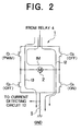
- Fig. 2 is a view illustrating operation of motor current detection upon occurrence of abnormality in the motor driving apparatus according to the first embodiment of the invention;
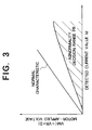
- Fig. 3 is a view for illustrating an abnormality decision range employed in the first embodiment of the invention; and
- Fig. 4 is a block diagram showing a configuration of a conventional motor driving apparatus known heretofore.
- Now, the present invention will be described in detail in conjunction with what is presently considered as preferred or typical embodiments thereof by reference to the drawings. In the following description, like reference characters designate like or corresponding parts throughout the several views.
- A first embodiment of the invention (i.e., exemplary mode for carrying out the invention) will be described by reference to Fig. 1 which is a block diagram showing generally a circuit configuration of a motor driving apparatus according to the first embodiment of the present invention. As can readily be understood from Fig. 1, the motor driving apparatus according to the instant embodiment of the invention differs from the conventional apparatus described hereinbefore by reference to Fig. 4 only in that some of the functions incorporated in the control means 20 are so modified as to implement the teachings of the present invention. Accordingly, like reference characters as those shown in Fig. 4 are used in Fig. 1 for designating the components similar or equivalent to those mentioned previously by reference to Fig. 4 and repeated description thereof will be omitted.
- Now referring to Fig. 1, the control means 20 is provided with an A/D (analogue/digital)
converter 21 for converting the detection signals, i.e., the steering torque T, the relay contact voltage VR and the detected current value Id, into corresponding digital signals, respectively, which are suited for processing executed by a microcomputer constituting the control means 20 and a drive control signal generating means 22 which serves to generate drive control signals C1 to C4 for the drivingcircuits 6 to 9, respectively, on the basis of the steering torque T, the relay contact voltage VR and the detected current value Id which are indicated by the digital signals obtained as the outputs of the A/D converter 21, as mentioned above. So long as the arrangement mentioned above is concerned, the function and configuration of the motor driving apparatus according to the instant embodiment of the invention is substantially same as those of the conventional motor driving apparatus described hereinbefore by reference to Fig. 4. - According to the present invention incarnated in the first embodiment, the control means 20 is further provided with an abnormality decision range setting means 23 for setting an abnormality decision range FR (see Fig. 3) on the basis of a relation between the duty ratio values of the PWM signals for those of the transistors Q1 to Q4 which are operated under the PWM control and the detected current value Id, i.e., the detected value of the current flowing through the H-bridge circuit to the
motor 2 and an abnormality decision means 24 for deciding abnormality of the detected current value Id when both the motor-applied voltage and the detected current value Id fall within the abnormality decision range FR, to thereby output an abnormality decision signal E to the drive control signal generating means 22. - On the other hand, the drive control signal generating means 22 is so arranged as to respond to the abnormality decision signal E when the detected current value Id indicates abnormality, to thereby drive both the other resistors (e.g. transistors Q1 and Q4) connected to the
power supply source 3 and the ground GND, respectively, (i.e., inserted at the sides of thepower supply source 3 and the ground potential GND, respectively, under the PWM control. - Besides, the control means 20 includes a stop condition setting means 25 for setting the stop condition for deenergizing or turning off the
relay 4 and a stop condition decision means 26 which responds to the abnormality decision signal E to thereby decide whether the stop condition is satisfied or not, when abnormality of the detected current value Id is determined. - When the stop condition is met, the stop condition decision means 26 outputs the stop signal S to the
relay 4 to thereby make therelay 4 stop the power supply to the H-bridge circuit 1. - By way of example, the stop condition decision means 26 may be so arranged that in response to the abnormality decision signal E indicating abnormality of the detected current value Id, the stop condition decision means 26 outputs the stop signal S so long as the abnormality decision range FR is validated even in the state where both the transistors Q1 and Q4 are driven under the PWM control.
- Further, the stop condition decision means 26 may be so implemented as to decrease gradually the duty ratio value of the PWM signals P1 and P4 and hence the motor current IM when the abnormality decision range FR is invalidated as a result of driving of both the transistors Q1 and Q4 under the PWM control upon occurrence of abnormality in the detected current value Id and issue the stop signal S only when the detected current value Id is decreased to a predetermined current value (e.g. when the detected current value Id becomes approximately zero).
- On the other hand, the stop condition for generating the stop signal S is so established that a system such as a motor-driven power steering system of a motor vehicle which employs the
electric motor 2 can be protected against degradation of safety even when theelectric motor 2 is stopped. By way of example, assuming that theelectric motor 2 of the motor driving apparatus according to the invention is employed in a power steering system of a motor vehicle, the condition for generating the stop signal S may be so established that stoppage of theelectric motor 2 does not impair safety of a driver of the motor vehicle even when operation of theelectric motor 2 is stopped. In that case, the stop condition decision means 26 may be so arranged as to allow the stop signal S to be outputted when the steering torque T applied by the driver assumes a value smaller than a predetermined magnitude. - Furthermore, the stop condition decision means 26 may be so implemented as to allow the stop signal S to be outputted when the
electric motor 2 is not positively driven or when the motor current IM is smaller than a predetermined value. - Next, referring to Figs. 2 and 3, description will be directed to operation of the motor driving apparatus according to the first embodiment of the invention shown in Fig. 1.
- It is now assumed that the transistors Q2 and Q3 are constantly turned off with the transistor Q4 being constantly turned on whereas the transistor Q1 is driven under the PWM control (i.e., driven by using a pulse width modulated signal whose duty ratio can be controlled), to thereby control the motor current IM, as illustrated in Fig. 2.
- In the state where the motor current IM is controlled in this manner, it is again assumed that abnormality (1), (2) or (3) mentioned below take place. On the basis of such assumption, description will be made in what manner these abnormalities can be coped with according to the invention incarnated in the first embodiment thereof.
- At this juncture, it should be mentioned that the abnormality decision range FR shown in Fig. 3 is set by the abnormality decision range setting means 23. More specifically, the voltage applied to the
motor 2, i.e., motor-applied voltage
- In this case, the transistor Q1 assumes constantly conducting state (i.e., on state) with the PWM signal P1 being rendered invalid or ineffective, which results in increasing of the motor current IM. Consequently, the relation between the motor-applied voltage VM (determined on the basis of the relay contact voltage VR and the duty ratio value D of the PWM signal P1) and the detected current value Id may fall within the abnormality decision range FR.
- Consequently, the abnormality decision means 24 decides abnormality of the detected current value Id (and hence the motor driving current) to thereby output an abnormality decision signal E.
- In this conjunction, it should be noted that because the abnormality decision is made by checking whether or not the relation mentioned above falls within the abnormality decision range FR, the decision can be conducted with high reliability regardless of variations of the duty ratio value D and/or the detected current value Id.
- In response to the abnormality decision signal E, the drive control signal generating means 22 outputs to the
driving circuit 9 the drive control signal C4 for applying the PWM signal P4 to the transistor Q4 to thereby drive both the transistors Q1 to Q4 concurrently under the PWM control. - In that case, it will however be appreciated that the transistor Q1 continues to remain in the conducting or on state because of the short-circuit fault.
- The state mentioned above is substantially equivalent to the state in which the transistor Q1 is continuously turned on with the transistor Q4 being driven under the PWM control.
- As a result of this, the detected current value Id tends to assume a value close to that of the normal characteristic (see Fig. 3), which in turn means that operation of the motor driving apparatus can be continued for the time being. Besides, because of restoration to the state approximating the normal one, it can be identified or decided that the abnormality now of concern is ascribable to the short-circuit fault of the transistor Q1.
- Subsequently, the duty ratio value D is progressively diminished to thereby reduce gradually the motor current IM. At the time point when the detected current value Id of the motor current IM becomes substantially equal to zero, the stop signal S is outputted to thereby stop or interrupt the power supply to the H-
bridge circuit 1 and hence to theelectric motor 2. - Thus, when a short-circuit fault occurs in the transistor Q1, operation of the
electric motor 2 can be stopped smoothly while ensuring safety for a system associated with themotor 2. - Thereafter, the H-
bridge circuit 1 is repaired by exchanging the transistor Q1 with a sound one to restore the normal state of the H-bridge circuit 1, whereupon the drive control for the H-bridge circuit 1 can be performed in the ordinary manner. - Because the short-circuit fault occurs in the transistor Q2 connected in series to the transistor Q4 which is held constantly in the conducting or on state, the motor current IM flowing to the
electric motor 2 is interrupted, whereas a large current I2 flows to the ground GND from thepower supply source 3, as can be seen in Fig. 2. - As a consequence, the detected current value Id increases within the abnormality decision range FR as shown in Fig. 3, substantially in the manner described previously, whereupon both the transistors Q1 and Q4 are concurrently driven under the PWM control.
- In that case, the duty ratio value of the PWM signals P1 and P4 applied concurrently to the transistors Q1 and Q4, respectively, are significantly decreased through feedback control performed by the control means 20 on the basis of the detected current value Id, the current I flowing to the H-
bridge circuit 1 can be effectively suppressed. - In this conjunction, it should however be noted that because no large current I2 can flow through the
electric motor 2, the detected current value Id continues to remain within the abnormality decision range FR. Furthermore, on the basis of the status mentioned above, it can be discriminatively identified that the short-circuit fault now of concern does not take place in the transistor Q1. - Because the motor current IM can scarcely flow through the
electric motor 2 when the short-circuit fault occurs in the transistor Q3 connected in series to the transistor Q1 driven under the PWM control, a large current I3 flows from thepower supply source 3 to the ground GND, as can be seen in Fig. 2. - Consequently, the detected current value Id increases up to a level which falls within the abnormality decision range FR, as in the case of the short-circuit fault of the transistor Q2, whereby the transistors Q1 and Q4 are simultaneously put into PWM operation.
- In this case, the PWM duty ratio value for the transistors Q1 and Q4 are reduced under the effect of the feedback control of the detected current value Id through the control means 20, involving effective reduction of the detected current value Id.
- In this case, because the large current I3 can not flow through the
electric motor 2, as in the case of the short-circuit fault of the transistor Q2, the detected current value Id is prevented from going out of the abnormality decision range FR. Thus, it can be identified that the abnormal state now of concern is not due to the short-circuit fault of the transistor Q1. - More specifically, in the case of the short-circuit fault of the transistor Q1 mentioned above, the detected current value Id assumes a value corresponding to the motor current IM. Thus, the motor current IM can be controlled. However, in the case of the short-circuit fault of the transistors Q1 or Q3, the detected current value Id does not represents the motor current IM, rendering it impossible to control the motor current IM.
- Thus, when the detected current value Id does not go out of the abnormality decision range FR notwithstanding of the PWM-driving of the transistor Q1 and Q4 upon decision of abnormality, as in the case of the short-circuit faults (2) and (3) mentioned above, continuation of the power supply to the H-
bridge circuit 1 is of no use. Accordingly, the stop condition decision means 26 outputs immediately the stop signal S with preference being put on the protection of thepower supply source 3, to thereby deenergize therelay 4 for interrupting the power supply to the H-bridge circuit 1. - In other words, only when the abnormality which permits the control of the motor current IM takes place, as in the case of the short-circuit fault (1) mentioned previously, the control of the
electric motor 2 is continued to reduce gradually the power supply to a level at which the motor operation can be smoothly stopped, from the standpoint of safety. On the other hand, when such abnormality takes place which makes it impossible to control the motor current IM, as in the case of the short-circuit faults (2) and (3) mentioned previously, the power supply is instantaneously interrupted in order to protect thepower supply source 3, therelay 4, a fuse (not shown) and others by obviating load imposed to these elements. - In the case of the first embodiment of the motor driving apparatus according to the invention, it has been assumed that the electric motor constituting a part of the motor driving apparatus is to serve for producing an assist torque for the motor-driven power steering system. It should be however appreciated that the electric motor of concern may be one employed in other applications.
- In that case, other types of sensors may be used in place of the
torque sensor 30 employed for detecting the steering torque T in dependence on various applications. - Furthermore, in the case of the motor driving apparatus according to the first embodiment of the invention described hereinbefore, the duty ratio value of the PWM signal for controlling the H-
bridge circuit 1 is decreased progressively to thereby reduce gradually the motor current IM with theelectric motor 2 being stopped after suppression of shock otherwise given to the load, with a view to ensuring the safety for the motor-driven power steering system as well as operator thereof, when it is possible to control the motor current IM with the PWM driving operation effectuated in response to abnormality decision, while when it is impossible to control the motor current IM, the stop signal S is outputted instantaneously. In this conjunction, the stop condition for allowing the stop signal to be generated instantaneously may be altered so long as the safety of a driver of a motor vehicle equipped with a power steering system including a motor controlled according to the teachings of the invention can be ensured even when theelectric motor 2 is stopped instantaneously. - By way of example, the stop condition decision means 26 may be so implemented that the stop signal S is outputted immediately after the decision of abnormality to thereby interrupt the power supply to the
electric motor 2 when the steering torque T applied by the driver is smaller than a predetermined value, i.e., when the steering wheel is in a neutral state where substantially no steering operation is performed. - Furthermore, the stop condition decision means 26 may also be so implemented that when the motor vehicle is running at a high speed with the
electric motor 2 being placed in the non-operating state or when the motor current IM is smaller than a predetermined value, indicating that the motor assumes a state approximating the non-operating state, the stop signal may be outputted immediately upon decision of abnormality. - In the case of the motor driving apparatus according to the first embodiment of the invention, the abnormality decision range FR is set by taking into consideration the voltage applied to the H-
bridge circuit 1, i.e., the relay contact voltage VR. However, to this end, the output voltage of thepower supply source 3 may equally be made use so far as the voltage drop appearing across therelay 4. Further, the voltage applied to the H-bridge circuit 1 can be neglected when the power source voltage can be considered to be constant. - In this way, the abnormality decision range FR can be established on the basis of a relation between the duty ratio value D of the PWM signal and the detected current value Id.
- Many modifications and variations of the present invention are possible in the light of the above techniques. It is therefore to be understood that within the scope of the appended claims, the invention may be practiced otherwise than as specifically described.
Claims (10)
- An apparatus for driving an electric motor (2) comprising:a plurality of transistors (Q1 to Q4) constituting an H-bridge circuit (1);a power supply source (3) connected to one end of said H-bridge circuit (1);a relay (4) inserted between said one end (1c) of said H-bridge circuit (1) and said power supply source (3);a ground (GND) connected to other end (1d) of said H-bridge circuit (1);a plurality of driving circuits (6 to 9) for applying a pulse-width modulated signal (P1, P2, P3, P4) or a turn-on signal selectively to each of said transistors (Q1 to Q4);control means (20) for controlling on/off operation of said relay (4) and each of said driving circuits (6 to 9);
wherein said control means (20) turns off one (e.g. Q2) of said transistors (Q1; Q2) inserted at the side of said power supply source (3) and one (e.g. Q3) of said transistors (Q3; Q4) inserted at the side of said ground (GND);
while driving the other one (e.g. Q1) of said transistors (Q1; Q2) inserted at the side of said power supply source (3) and the other one (e.g. Q4) of said transistors (Q3; Q4) inserted at the side of said ground (GND) under pulse-width modulation control or in an on state;said electric motor (2) being connected between output terminals (1a, 1b) of said H-bridge circuit (1);current detecting circuit (12) for detecting an electric current (I) flowing to said H-bridge circuit (1);
wherein said control means (20) comprises abnormality decision means (24) for determining abnormality of a detected current value (Id) outputted from said current detecting circuit (12); and
wherein when said detected current value (Id) indicates abnormality, both of said other ones (Q1 and Q4) of said transistors (Q1 to Q4) inserted at the sides of said power supply source (3) and said ground (GND), respectively, are driven under the pulse-width modulation control. - A motor driving apparatus according to claim 1,
said abnormality decision means (24) further comprising:abnormality decision range setting means (23) for setting an abnormality decision range (FR) on the basis of a relation between a duty ratio value (D) of the pulse-width modulated signal (P1, P2, P3, P4) applied to the transistors (Q1 to Q4) driven under the pulse-width modulated control and said detected current value (Id);
wherein abnormality of said detected current value (Id) is determined when said duty ratio value (D) and said detected current value (Id) fall within said abnormality decision range (FR). - A motor driving apparatus according to claim 1,
said control means (20) further comprising:stop condition setting means (25) for setting stop condition for turning off said relay (4); andstop condition decision means (26) for deciding whether said stop condition is met or not when abnormality of said detected current value (Id) is determined;
wherein when said stop condition is met, a stop signal (S) is outputted to said relay (4) to thereby stop electric power supply to said H-bridge circuit (1). - A motor driving apparatus according to claim 3,
wherein said stop condition decision means (26) outputs said stop signal (S) so long as no departure from said abnormality decision range (FR) is detected even when both of said transistors are driven under the pulse-width modulation control upon determination of abnormality of said detected current value (Id). - A motor driving apparatus according to claim 3,
wherein said stop condition decision means (26) decreases gradually a motor current (IM) supplied to said electric motor (2) so long as departure from said abnormality decision range (FR) is detected when both of transistors (e.g. Q1; Q4 or Q2; Q3) are driven under the pulse-width modulation control upon determination of abnormality of said detected current value (Id), while outputting said stop signal (S) when said detected current value (Id) becomes lower than a predetermined current inclusive thereof. - A motor driving apparatus according to claim 1,
said electric motor (2) being a motor which generates an assist steering torque for a motor-driven power steering system of a motor vehicle;
wherein said control means (20) incudes a drive control signal generating means (22) for determining a motor current (IM) supplied to said electric motor (2) in dependence on a steering torque (T) applied by a drier of said motor vehicle. - A motor driving apparatus according to claim 3,
said electric motor (2) being a motor which generates an assist steering torque for a motor-driven power steering system of a motor vehicle;
wherein said stop condition is so determined that safety of a driver of said motor vehicle can be ensured even when said electric motor (2) is stopped. - A motor driving apparatus according to claim 7,
wherein said stop condition decision means (26) outputs said stop signal (S) unless a steering torque (T) applied by said driver is greater than a predetermined value. - A motor driving apparatus according to claim 7,
wherein said stop condition decision means (26) outputs said stop signal (S) unless the motor current (IM) supplied to said electric motor (2) is greater than a predetermined value. - A motor driving apparatus according to claim 5,
said electric motor (2) being a motor which generates an assist steering torque for a motor-driven power steering system of a motor vehicle;
wherein said control means (20) incudes drive control signal generating means (22) for determining said motor current (IM) in dependence on a steering torque (T) applied by a driver of said motor vehicle.
Applications Claiming Priority (2)
| Application Number | Priority Date | Filing Date | Title |
|---|---|---|---|
| JP89675/96 | 1996-04-11 | ||
| JP08967596A JP3518944B2 (en) | 1996-04-11 | 1996-04-11 | Motor drive |
Publications (3)
| Publication Number | Publication Date |
|---|---|
| EP0800979A2 true EP0800979A2 (en) | 1997-10-15 |
| EP0800979A3 EP0800979A3 (en) | 1998-06-03 |
| EP0800979B1 EP0800979B1 (en) | 1999-05-19 |
Family
ID=13977336
Family Applications (1)
| Application Number | Title | Priority Date | Filing Date |
|---|---|---|---|
| EP96115030A Expired - Lifetime EP0800979B1 (en) | 1996-04-11 | 1996-09-19 | Electric motor driving apparatus |
Country Status (4)
| Country | Link |
|---|---|
| US (1) | US5889376A (en) |
| EP (1) | EP0800979B1 (en) |
| JP (1) | JP3518944B2 (en) |
| DE (1) | DE69602516T2 (en) |
Cited By (14)
| Publication number | Priority date | Publication date | Assignee | Title |
|---|---|---|---|---|
| EP0939214A3 (en) * | 1998-02-26 | 2000-01-12 | Denso Corporation | Apparatus for detecting abnormality in direct current motor driving system |
| FR2802492A1 (en) * | 1999-12-16 | 2001-06-22 | Mitsubishi Electric Corp | ELECTRIC ASSISTANCE STEERING SYSTEM |
| WO2002078030A1 (en) | 2001-03-23 | 2002-10-03 | Bruce Stanley Gunton | Control arrangement |
| EP1184256A3 (en) * | 2000-08-28 | 2002-12-18 | Denso Corporation | Electrically-driven power steering system having failure detection function |
| US6615152B2 (en) | 2001-03-27 | 2003-09-02 | Mitsubishi Denki Kabushiki Kaisha | Abnormality detecting method and device for position detecting device, and electric power steering device |
| WO2003080159A1 (en) * | 2002-03-27 | 2003-10-02 | Novo Nordisk A/S | A safety system for an electrically driven medical delivery device and a computer-readable medium |
| WO2003099632A1 (en) * | 2002-05-24 | 2003-12-04 | Robert Bosch Gmbh | Electronically commutable motor |
| US6691817B2 (en) | 2001-02-03 | 2004-02-17 | Trw Lucasvarity Electric Steering Ltd. | Electrical power-assisted steering systems |
| FR2874886A1 (en) * | 2004-09-07 | 2006-03-10 | Mitsubishi Electric Corp | POWER ASSISTED STEERING CONTROL |
| EP1855377A1 (en) * | 2006-05-08 | 2007-11-14 | Integrated Dynamics Engineering GmbH | Electric motor control |
| US7597679B2 (en) | 2002-03-27 | 2009-10-06 | Novo Nordisk A/S | Safety system for an electrically driven medical delivery device and a computer-readable medium |
| FR2998117A1 (en) * | 2012-11-14 | 2014-05-16 | Mitsubishi Electric Corp | MOTOR CONTROL DEVICE, MOTOR CONTROL METHOD, AND ELECTRIC POWER STEERING DEVICE |
| FR3056039A1 (en) * | 2016-09-14 | 2018-03-16 | Continental Automotive France | METHOD FOR SUPPLYING AN INDUCTIVE LOAD |
| US10574173B2 (en) | 2016-09-02 | 2020-02-25 | Kongsberg Inc. | Techniques for limiting electrical current provided to a motor in an electric power steering system |
Families Citing this family (36)
| Publication number | Priority date | Publication date | Assignee | Title |
|---|---|---|---|---|
| JPH0787602A (en) * | 1993-09-17 | 1995-03-31 | Matsushita Electric Ind Co Ltd | Electric vehicle protection device |
| JPH10271889A (en) * | 1997-03-28 | 1998-10-09 | Komatsu Ltd | Electric power steering controller |
| WO1998058833A1 (en) * | 1997-06-20 | 1998-12-30 | Mitsubishi Denki Kabushiki Kaisha | Motor driven power steering device |
| JPH1134892A (en) * | 1997-07-24 | 1999-02-09 | Honda Motor Co Ltd | Electric power steering device |
| US6069428A (en) * | 1998-01-21 | 2000-05-30 | Fasco Industries, Inc. | Brushless DC motor assembly |
| JP3034508B1 (en) * | 1998-11-12 | 2000-04-17 | 本田技研工業株式会社 | Motor drive |
| JP3752882B2 (en) * | 1999-04-01 | 2006-03-08 | 豊田工機株式会社 | Electric power steering control device |
| JP4011816B2 (en) | 2000-02-17 | 2007-11-21 | アルプス電気株式会社 | Motor drive device |
| JP3700547B2 (en) * | 2000-06-29 | 2005-09-28 | 三菱電機株式会社 | Electric power steering device |
| JP3511593B2 (en) * | 2000-11-10 | 2004-03-29 | 三菱電機株式会社 | Electric power steering control device |
| JP4461615B2 (en) * | 2000-12-13 | 2010-05-12 | 株式会社デンソー | Control device for electric power steering mechanism |
| US6763804B2 (en) | 2001-10-09 | 2004-07-20 | Visteon Global Technologies, Inc. | Electronic throttle servo overheat protection system |
| US6731085B2 (en) | 2002-04-02 | 2004-05-04 | Trw Inc. | Method and apparatus for determining motor faults in an electric assist steering system |
| JP2003300473A (en) * | 2002-04-10 | 2003-10-21 | Nsk Ltd | Electric power steering device |
| JP3854190B2 (en) * | 2002-04-26 | 2006-12-06 | 株式会社ジェイテクト | Motor control device |
| FR2860108B1 (en) * | 2003-09-24 | 2007-01-19 | Johnson Contr Automotive Elect | SYNCHRONOUS RECTIFIER DEVICE AND SYNCHRONOUS ELECTRIC MACHINE USING THE DEVICE |
| US7207412B2 (en) * | 2004-02-17 | 2007-04-24 | Denso Corporation | Motor-driven power steering system |
| JP4409313B2 (en) * | 2004-02-24 | 2010-02-03 | 株式会社デンソー | Brushless motor drive device |
| US8091679B2 (en) * | 2004-04-28 | 2012-01-10 | Nsk Ltd. | Electric power steering device |
| US7483796B2 (en) * | 2004-12-08 | 2009-01-27 | Trw Automotive U.S. Llc | Method and apparatus for determining faults in an electric assist steering system |
| JP2006211825A (en) * | 2005-01-28 | 2006-08-10 | Nsk Ltd | Power steering device |
| JP4765779B2 (en) * | 2005-07-19 | 2011-09-07 | 株式会社デンソー | Control device, short detection device, load drive system and program |
| CN101300108B (en) | 2005-11-04 | 2012-08-08 | 罗伯特·博世有限公司 | Rotary drill with optical speed control and method of operation |
| JP2007225388A (en) * | 2006-02-22 | 2007-09-06 | Nsk Ltd | Electric power steering device |
| JP4294039B2 (en) * | 2006-06-23 | 2009-07-08 | 三菱電機株式会社 | Power steering device |
| DE102008021854A1 (en) * | 2008-05-02 | 2009-11-05 | Volkswagen Ag | Device and method for monitoring possible errors in a technical device, in particular servo steering system |
| JP5266913B2 (en) * | 2008-07-02 | 2013-08-21 | 日本精工株式会社 | Control device for electric power steering device |
| JP5180714B2 (en) * | 2008-07-17 | 2013-04-10 | ルネサスエレクトロニクス株式会社 | Load short-circuit protection circuit |
| CN103648832B (en) * | 2011-07-14 | 2015-07-29 | 丰田自动车株式会社 | The actuating device of vehicle |
| JP5660997B2 (en) * | 2011-08-08 | 2015-01-28 | オムロンオートモーティブエレクトロニクス株式会社 | Electric motor control device |
| DE102011112273A1 (en) * | 2011-09-05 | 2013-03-07 | Brose Fahrzeugteile Gmbh & Co. Kg, Hallstadt | Drive arrangement for the motorized adjustment of an adjusting element of a motor vehicle |
| KR101360436B1 (en) * | 2011-12-09 | 2014-02-12 | 기아자동차주식회사 | Pulse width modulation controller |
| DK3474760T3 (en) | 2016-06-27 | 2023-03-20 | Galvanize Therapeutics Inc | Generator and a catheter with an electrode for treating a lung passage |
| KR102569824B1 (en) * | 2018-10-29 | 2023-08-23 | 현대모비스 주식회사 | Apparatus and method for protecting a vehicle |
| US11638819B2 (en) * | 2020-09-11 | 2023-05-02 | Galvanize Therapeutics, Inc. | Signal generators for use with tissue modification systems |
| US11502629B2 (en) * | 2020-12-30 | 2022-11-15 | Texas Instruments Incorporated | Hardware based motor drive controller |
Family Cites Families (12)
| Publication number | Priority date | Publication date | Assignee | Title |
|---|---|---|---|---|
| JPS6311480A (en) * | 1986-06-30 | 1988-01-18 | Kayaba Ind Co Ltd | Control unit for electric power steering |
| KR900008393B1 (en) * | 1986-10-02 | 1990-11-17 | 미츠비시 덴키 가부시키가이샤 | Over current protection circuit for inverter apparatus |
| JP2570782B2 (en) * | 1987-12-25 | 1997-01-16 | アイシン精機株式会社 | Overcurrent control device for electric drive source |
| JPH07115643B2 (en) * | 1988-04-28 | 1995-12-13 | 三菱電機株式会社 | Electric power steering device |
| JP2597170B2 (en) * | 1988-12-13 | 1997-04-02 | 日本輸送機株式会社 | Overcurrent protection method for electric power steering device |
| JPH0811536B2 (en) * | 1989-09-14 | 1996-02-07 | 株式会社日立製作所 | Current controller for motor drive |
| JP2659108B2 (en) * | 1991-04-26 | 1997-09-30 | 本田技研工業株式会社 | Motor drive control device |
| JP2857555B2 (en) * | 1993-01-27 | 1999-02-17 | 三菱電機株式会社 | Electric power steering device |
| EP0631922B1 (en) * | 1993-07-02 | 1997-03-05 | Koyo Seiko Co., Ltd. | Electric power steering apparatus |
| US5457364A (en) * | 1994-01-18 | 1995-10-10 | Allegro Microsystems, Inc. | Bridge motor driver with short-circuit protection and motor-current limiting feature |
| JPH07251749A (en) * | 1994-03-16 | 1995-10-03 | Mitsubishi Electric Corp | Electric power steering controller |
| US5642247A (en) * | 1995-07-21 | 1997-06-24 | Harris Corporation | Automatic fault monitoring system and motor control system incorporating same |
-
1996
- 1996-04-11 JP JP08967596A patent/JP3518944B2/en not_active Expired - Fee Related
- 1996-09-19 DE DE69602516T patent/DE69602516T2/en not_active Expired - Lifetime
- 1996-09-19 EP EP96115030A patent/EP0800979B1/en not_active Expired - Lifetime
- 1996-10-28 US US08/739,050 patent/US5889376A/en not_active Expired - Lifetime
Cited By (21)
| Publication number | Priority date | Publication date | Assignee | Title |
|---|---|---|---|---|
| US6154351A (en) * | 1998-02-26 | 2000-11-28 | Denso Corporation | Apparatus for detecting abnormality in direct current motor driving system |
| EP0939214A3 (en) * | 1998-02-26 | 2000-01-12 | Denso Corporation | Apparatus for detecting abnormality in direct current motor driving system |
| FR2802492A1 (en) * | 1999-12-16 | 2001-06-22 | Mitsubishi Electric Corp | ELECTRIC ASSISTANCE STEERING SYSTEM |
| EP1184256A3 (en) * | 2000-08-28 | 2002-12-18 | Denso Corporation | Electrically-driven power steering system having failure detection function |
| US6691817B2 (en) | 2001-02-03 | 2004-02-17 | Trw Lucasvarity Electric Steering Ltd. | Electrical power-assisted steering systems |
| WO2002078030A1 (en) | 2001-03-23 | 2002-10-03 | Bruce Stanley Gunton | Control arrangement |
| US7333308B2 (en) | 2001-03-23 | 2008-02-19 | Bruce Stanley Gunton | Control arrangement |
| US6615152B2 (en) | 2001-03-27 | 2003-09-02 | Mitsubishi Denki Kabushiki Kaisha | Abnormality detecting method and device for position detecting device, and electric power steering device |
| US7597679B2 (en) | 2002-03-27 | 2009-10-06 | Novo Nordisk A/S | Safety system for an electrically driven medical delivery device and a computer-readable medium |
| CN100435868C (en) * | 2002-03-27 | 2008-11-26 | 诺沃挪第克公司 | A security system and a computer-readable medium for an electrically actuated medical transmission device |
| WO2003080159A1 (en) * | 2002-03-27 | 2003-10-02 | Novo Nordisk A/S | A safety system for an electrically driven medical delivery device and a computer-readable medium |
| US7019479B2 (en) | 2002-05-24 | 2006-03-28 | Robert Bosch Gmbh | Electronically commutable motor |
| WO2003099632A1 (en) * | 2002-05-24 | 2003-12-04 | Robert Bosch Gmbh | Electronically commutable motor |
| CN100387475C (en) * | 2002-05-24 | 2008-05-14 | 罗伯特-博希股份公司 | electronically commutated motor |
| FR2874886A1 (en) * | 2004-09-07 | 2006-03-10 | Mitsubishi Electric Corp | POWER ASSISTED STEERING CONTROL |
| EP1855377A1 (en) * | 2006-05-08 | 2007-11-14 | Integrated Dynamics Engineering GmbH | Electric motor control |
| FR2998117A1 (en) * | 2012-11-14 | 2014-05-16 | Mitsubishi Electric Corp | MOTOR CONTROL DEVICE, MOTOR CONTROL METHOD, AND ELECTRIC POWER STEERING DEVICE |
| US10574173B2 (en) | 2016-09-02 | 2020-02-25 | Kongsberg Inc. | Techniques for limiting electrical current provided to a motor in an electric power steering system |
| FR3056039A1 (en) * | 2016-09-14 | 2018-03-16 | Continental Automotive France | METHOD FOR SUPPLYING AN INDUCTIVE LOAD |
| WO2018050991A1 (en) * | 2016-09-14 | 2018-03-22 | Continental Automotive France | Method for supplying an inductive load |
| US10479402B2 (en) | 2016-09-14 | 2019-11-19 | Continental Automotive France | Method for supplying an inductive load |
Also Published As
| Publication number | Publication date |
|---|---|
| DE69602516T2 (en) | 1999-10-28 |
| US5889376A (en) | 1999-03-30 |
| EP0800979B1 (en) | 1999-05-19 |
| EP0800979A3 (en) | 1998-06-03 |
| JPH09285182A (en) | 1997-10-31 |
| DE69602516D1 (en) | 1999-06-24 |
| JP3518944B2 (en) | 2004-04-12 |
Similar Documents
| Publication | Publication Date | Title |
|---|---|---|
| US5889376A (en) | Motor driving apparatus | |
| US4532567A (en) | Electric power steering stall protection circuit | |
| US6816765B2 (en) | Motor-driven power steering control apparatus | |
| JP3460885B2 (en) | Electric power steering control device | |
| KR100386174B1 (en) | Apparatus for detecting abnormality of motor driving device for steering of vehicle | |
| US6332506B1 (en) | Motor driven power steering device | |
| US5602735A (en) | Control apparatus for motor-driven power steering system in which power suppy to an electric clutch is reduced upon detection of a malfunction | |
| EP0708010B1 (en) | Electric power steering apparatus | |
| US6268708B1 (en) | Control apparatus for electric power steering system | |
| US20080004773A1 (en) | Control device for electric power steering apparatus | |
| EP1319576B1 (en) | Control apparatus of electric power steering | |
| EP1738990B1 (en) | Voltage boosting circuit and electrically-driven power steering device | |
| US7355361B2 (en) | Motor control apparatus | |
| US5039926A (en) | Motorized power steering apparatus | |
| US20020024317A1 (en) | Electrically-driven power steering system having failure detection function | |
| US7128184B2 (en) | Motor-driven power steering control apparatus | |
| JP5125432B2 (en) | Control device for electric power steering device and control device for motor | |
| JP3572801B2 (en) | Electric power steering device | |
| JP3163920B2 (en) | Electric power steering device and control unit used for it | |
| JP3511563B2 (en) | Electric power steering control device | |
| JPH05131940A (en) | Vehicle auxiliary device drive system and control unit thereof | |
| JP2021106448A (en) | Circuit board | |
| JPH0311942B2 (en) | ||
| KR100352359B1 (en) | An electric-power-steering controller | |
| JP2612744B2 (en) | Control method for steering motor of four-wheel steering device |
Legal Events
| Date | Code | Title | Description |
|---|---|---|---|
| PUAI | Public reference made under article 153(3) epc to a published international application that has entered the european phase |
Free format text: ORIGINAL CODE: 0009012 |
|
| AK | Designated contracting states |
Kind code of ref document: A2 Designated state(s): DE FR GB |
|
| PUAL | Search report despatched |
Free format text: ORIGINAL CODE: 0009013 |
|
| AK | Designated contracting states |
Kind code of ref document: A3 Designated state(s): DE FR GB |
|
| 17P | Request for examination filed |
Effective date: 19980618 |
|
| GRAG | Despatch of communication of intention to grant |
Free format text: ORIGINAL CODE: EPIDOS AGRA |
|
| 17Q | First examination report despatched |
Effective date: 19980821 |
|
| GRAG | Despatch of communication of intention to grant |
Free format text: ORIGINAL CODE: EPIDOS AGRA |
|
| GRAH | Despatch of communication of intention to grant a patent |
Free format text: ORIGINAL CODE: EPIDOS IGRA |
|
| GRAH | Despatch of communication of intention to grant a patent |
Free format text: ORIGINAL CODE: EPIDOS IGRA |
|
| GRAA | (expected) grant |
Free format text: ORIGINAL CODE: 0009210 |
|
| AK | Designated contracting states |
Kind code of ref document: B1 Designated state(s): DE FR GB |
|
| REF | Corresponds to: |
Ref document number: 69602516 Country of ref document: DE Date of ref document: 19990624 |
|
| ET | Fr: translation filed | ||
| PLBE | No opposition filed within time limit |
Free format text: ORIGINAL CODE: 0009261 |
|
| STAA | Information on the status of an ep patent application or granted ep patent |
Free format text: STATUS: NO OPPOSITION FILED WITHIN TIME LIMIT |
|
| 26N | No opposition filed | ||
| REG | Reference to a national code |
Ref country code: GB Ref legal event code: IF02 |
|
| PGFP | Annual fee paid to national office [announced via postgrant information from national office to epo] |
Ref country code: GB Payment date: 20100916 Year of fee payment: 15 |
|
| GBPC | Gb: european patent ceased through non-payment of renewal fee |
Effective date: 20110919 |
|
| PG25 | Lapsed in a contracting state [announced via postgrant information from national office to epo] |
Ref country code: GB Free format text: LAPSE BECAUSE OF NON-PAYMENT OF DUE FEES Effective date: 20110919 |
|
| PGFP | Annual fee paid to national office [announced via postgrant information from national office to epo] |
Ref country code: DE Payment date: 20140917 Year of fee payment: 19 |
|
| PGFP | Annual fee paid to national office [announced via postgrant information from national office to epo] |
Ref country code: FR Payment date: 20140906 Year of fee payment: 19 |
|
| REG | Reference to a national code |
Ref country code: DE Ref legal event code: R119 Ref document number: 69602516 Country of ref document: DE |
|
| REG | Reference to a national code |
Ref country code: FR Ref legal event code: ST Effective date: 20160531 |
|
| PG25 | Lapsed in a contracting state [announced via postgrant information from national office to epo] |
Ref country code: DE Free format text: LAPSE BECAUSE OF NON-PAYMENT OF DUE FEES Effective date: 20160401 |
|
| PG25 | Lapsed in a contracting state [announced via postgrant information from national office to epo] |
Ref country code: FR Free format text: LAPSE BECAUSE OF NON-PAYMENT OF DUE FEES Effective date: 20150930 |