EP0800780B1 - Apparatus and method for treating articles in solution with effervescent tablets - Google Patents
Apparatus and method for treating articles in solution with effervescent tablets Download PDFInfo
- Publication number
- EP0800780B1 EP0800780B1 EP97810191A EP97810191A EP0800780B1 EP 0800780 B1 EP0800780 B1 EP 0800780B1 EP 97810191 A EP97810191 A EP 97810191A EP 97810191 A EP97810191 A EP 97810191A EP 0800780 B1 EP0800780 B1 EP 0800780B1
- Authority
- EP
- European Patent Office
- Prior art keywords
- container
- channel
- treatment system
- closure
- tubular channel
- Prior art date
- Legal status (The legal status is an assumption and is not a legal conclusion. Google has not performed a legal analysis and makes no representation as to the accuracy of the status listed.)
- Expired - Lifetime
Links
Images


Classifications
-
- A—HUMAN NECESSITIES
- A61—MEDICAL OR VETERINARY SCIENCE; HYGIENE
- A61L—METHODS OR APPARATUS FOR STERILISING MATERIALS OR OBJECTS IN GENERAL; DISINFECTION, STERILISATION OR DEODORISATION OF AIR; CHEMICAL ASPECTS OF BANDAGES, DRESSINGS, ABSORBENT PADS OR SURGICAL ARTICLES; MATERIALS FOR BANDAGES, DRESSINGS, ABSORBENT PADS OR SURGICAL ARTICLES
- A61L12/00—Methods or apparatus for disinfecting or sterilising contact lenses; Accessories therefor
- A61L12/08—Methods or apparatus for disinfecting or sterilising contact lenses; Accessories therefor using chemical substances
-
- A—HUMAN NECESSITIES
- A45—HAND OR TRAVELLING ARTICLES
- A45C—PURSES; LUGGAGE; HAND CARRIED BAGS
- A45C11/00—Receptacles for purposes not provided for in groups A45C1/00-A45C9/00
- A45C11/005—Contact lens cases
Definitions
- This invention relates broadly to containers useful in facilitating mixing of solutions retained therein by application of gas bubbles. More specifically, this invention relates to contact lens care containers for use with effervescent tablets. In a preferred embodiment, this invention relates to containers for cleaning and disinfecting ophthalmic lenses.
- Contact lenses should be disinfected when removed in order to erradicate harmful microorganisms which may cause ocular diseases. It is common for consumers to remove lenses overnight and disinfect lenses daily. In addition, contact lenses should be cleaned periodically in order to remove lipid and protein deposits which impair vision. Ideally, the consumer would prefer to clean and disinfect contact lenses in a "one-step" process. Numerous compositions, methods and devices for disinfecting, cleaning and simultaneously cleaning and disinfecting contact lenses have been disclosed. Examples of patents and publications relating to cleaning and disinfecting follow.
- U.S. Patent No. 4,473,550 issued to Rosenbaum, et al. on Sep. 25, 1984, describes a method for disinfecting a contact lens with a three component solution.
- the solution includes a peroxide, a peroxidase within the classification E.C.
- the method involves storing the three components in a non-reacting state, then mixing in a liquid carrier for contact lens immersion therein.
- U.S. Patent No. 5,169,455 issued to Kessler on Dec. 8, 1992, discloses a method of simultaneously cleaning and disinfecting contact lenses with a proteolytic enzyme and a peroxidative reaction with donor and accceptor molecules.
- the composition disclosed uses a thiol agent as a color indicator.
- a preferred composition includes peroxidase, iodide, hydrogen peroxide, a protease and a thiol agent.
- Useful proteases disclosed include trypsin, collaginases, keratinase, elastase, aminopeptidases, carboxylases, pancreatin, pronases and subtilisin.
- U.S. Patent No. 5,186,317 issued to Ryder, et al. on Feb. 16, 1993, discloses a lens case for contact lens disinfection systems which use disinfecting tablets or catalysts.
- the system includes a cylindrical cup which has a reaction chamber in the bottom for holding a tablet.
- the reaction chamber has substantially reduced dimensions with respect to the cyclindrical main body portion of the cup.
- a saline solution or other disinfecting compound is then added to the cup.
- the bubbles rise and cause an upwardly directed stream in the solution, which disinfectingly encounters the contact lenses.
- a preferred method involves finger rubbing of the contact lens.
- the peroxide may be produced from a solid perborate which is in tablet form.
- the tablet may include a solid acid and a solid carbonate, which, when reacted in solution, generate a carbon dioxide effervescence for release of the perborate.
- EP-A-0 761 238 falls within the terms of Article 54(3) EPC.
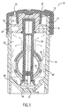
- FIGS. 1 and 2 are side sectional views of a contact lens treatment system 10 of the present invention.
- System 10 includes closure 12 which is releasably affixed, preferably via mating threading 14, to the top of container 16.
- the container is adapted to receive and hold ophthalmic lenses, especially contact lenses, and a volume of fluid sufficient to treat the lenses.
- the container has a substantially circular top opening and a closed bottom.
- a preferred container shape is cyclindrical.
- Preferred treatments are disinfection, cleaning, and both cleaning and disinfection. However, a variety of other treatments, such as lens lubrication or hydration, are within the scope of the invention.
- Closure 12 has deformable sealing means 18 affixed thereto by an interference fit between the top side walls of sealing means 18 and cylindrical extension member 20 at location 22.
- a substantially liquid-impermeable circular seal is formed between sealing means 18 and the interior walls of container 16 at two locations 24.
- the sealing of closure 12 to container 16 defines treatment chamber 26.
- the deformable sealing means prevents liquid held within the treatment chamber from leaking out when the system is tilted or turned upside down.
- Closure 12 also includes opening 28 extending through the closure to the ambient environment.
- sealing means 18 deform and allow gas to vent past the sealing means and through opening 28.
- the gas pressure may elevate during the lens treatment process, thereby causing venting to the environment.
- venting only occurs, if at all, during quick assembly by the user, and not continuously during the treatment process.
- opening 28 may vary widely (e.g., rectangular, oval, slits) .
- the invention is not limited to containers which have openings.
- a preferred shape of opening 28, with respect to manufacturing efficiency, is a circular opening. While only one opening is shown in this embodiment, it is clearly within the scope of the appended claims to have a plurality of openings extending through the closure.
- sealing and venting system illustrated in FIGS. 1 and 2 is a preferred system
- numerous other sealing and venting systems may be used in accordance with the present invention.
- Examples of other sealing and venting systems include those disclosed in U.S. Patent No. 4,011,941 (O-ring positioned in an annular groove passageway), issued to Parsons on Mar. 15, 1977 ; U.S. Patent No. 4,637,919 (cap includes a filter assembly positioned in a vent passageway), issued to Ryder, et al., Jan. 20, 1987; U.S. Patent No. 4,750,610 (gas vents around deflectable flange in cap and through loosely threaded container-cap connection), issued to Ryder, Jun. 14, 1988; U.S. Patent No.
- elongated member 30 is affixed to sealing means 18, which, in turn, is affixed to closure 12.
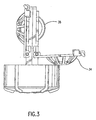
- Elongated member 30 supports lens-retaining means 32, which includes basket 34 and a convex-shaped dome member 36 (shown in FIG. 3).
- Basket 34 may be opened, as shown in FIG. 3, when the closure and attachments are removed from the container. Lenses may be inserted into or removed from each of the lens retaining means when basket 34 has been pivoted into an open position.
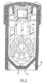
- FIG. 4 which is a bottom view of elongated support member 30 and lens-retaining means 32, illustrates channel 50 which extends upwardly through the center of elongated support member 30 towards the opening of the container.
- the channel may have a variety of shapes in cross section, including the more common square, oval, rectangular, and circular. There is no requirement that the channel have a uniform cross-sectional shape, but a uniform shape is believed to better promote flow due to reduced resistance relatively to non-uniform shapes.
- the rectangular cross sectional shape of channel 50 may be preferred from the perpective of manufacturing efficiency.
- channel 50 may vary somewhat depending on the specific application.
- the ideal length of the tubular channel is a function of the length of the container side walls.
- the tubular channel extends a distance at least 50% of the length from the closure to the container closed bottom end. More preferably, the channel extends a distance of 75% of the length from the closure to the container closed bottom end. More preferably, the channel extends a distance of 90% of the length from the closure to the container closed bottom end.
- a preferred length of channel 50, extending from the bottom of the container to the top, is about 4 mm to about 50 mm. More preferably, the length of channel 50 is between about 8 mm and about 30 mm.
- the cross-sectional area of channel 50 through which fluid flows preferably is within about 1 mm 2 to about 100 mm 2 , more preferably about 7 mm 2 to about 60 mm 2 .
- the channel is designed to promote fluid flow in a uniform direction, preferably upwardly towards channel opening 40 (See FIG. 2).
- fluid flow may be initiated when an effervescent tablet 37 begins generating gas (e.g., carbon dioxide), which rises through the fluid.
- gas e.g., carbon dioxide
- the rising gas bubbles induce a flow of fluid, and optional active agents, upward through channel 50, as shown by the arrows near the bottom of the container in FIG. 1.
- Gas exit through openings 40 (see upward arrows). If sufficient internal pressure develops, gas may eventually escape through sealing means 18 near seal locations 24 by deflecting or deforming the sealing means. The gas which passes through the sealing means finally exits the system through opening 28.
- fluid which was induced to flow upwardly with the gas also exits at openings 40 in channel 50.
- gravity causes the fluid, and optional suspended agents, which exits openings 40 to flow downward between elongated support member 30, through and between basket 34 and convex dome member 36, both in front of and behind the lenses.
- Fluid also flows downward between basket 34 and side walls 42 of the container (see downward arrows). This gas and fluid flow cycle continues as long as the effervescent tablet continues to generate gas.
- the effervescent tablet is located at the bottom of the container and substantially in the center. It is also preferable that the effervescent tablet be located nearly directly below channel 50, in order to promote the most uniform flow regime and the smallest concentration gradient.
- the system preferably includes a tablet alignment means.
- FIGS. 1 and 2 illustrate a preferred tablet alignment means.
- the means for tablet alignment may be selected from a variety of shapes designed to cause the tablet to self-align when dropped into the container.
- a preferred tablet alignment means is shown in FIGS. 1 and 2.
- Tablet alignment means 44 is a funnel-shaped bottom of container 16, which has an apex located in the center of the container. The central area of the bottom of the container is preferably horizontal when the container is resting upright, in normal use conditions. Central area 46 of the tablet alignment means is preferably slight greater than the longest dimension of the effervescent tablet to be used.
- central area 46 is circular and ranges from about 10 to about 200 mm 2 , more preferably about 25 to about 100 mm 2 , and even more preferably from about 35 to about 80 mm 2 .
- the peripheral walls 48 of the alignment means are preferably angled at about 120° to about 150° upwardly from the horizontal central area, and extend to meet vertical side walls 42 of the container.
- tablet alignment means 44 functions to essentially automatically and uniformly align the tablet into the center of the container bottom.
- the tablet may be inserted directly into the tubular channel.
- the tablet may be inserted into the bottom of the channel in the opening shown in FIG. 5.
- the tablet may be inserted from the top of the tubular channel.
- an opening may be formed in one of the sides of the tubular channel for insertion of the tablet.
- the baffles or protuberances shown in the FIG. 6 embodiment may perform this tablet retention function.
- One advantage of locating the tablet in the tubular channel is that no additional tablet alignment means in the bottom of the container is necessary.
- the FIG. 5 embodiment also includes a flow guide member 64 affixed to the bottom end of tubular channel 60.
- a side sectional view of the flow guide member is shown in FIG. 6.
- Flow guide member 64 is a conical or funnel shaped extension member which is formed when baskets 34 are closed over dome 36.
- Flow guide member 64 flares outwardly from the bottom of channel 60.
- the flow guide member provides a means for funneling the effervescent bubbles and fluid flow into the tubular channel, thereby reducing the likelihood of stagnation points or disruptive countercurrents.
- the flow guide member may also be added to improve concentration uniformity throughout the treatment container.
- flow guide member 64 aids in aligning the tablet in the center of the container bottom.
- the flow guide member extends a distance of about one millimeter to about 10 millimeters from the bottom edge of the tubular channel.
- the flow guide member is preferably concave in shape, having a radius of curvature of about 1 to about 10 mm, more preferably about 3 to about 5 mm.
- the flow guide member preferably has an angle of about 30° to 60° with the tubular channel.
- the components of the treatment system may be formed from a wide variety of materials.
- the sealing and venting means is formed from a resiliently flexible material so that the rims may be deformed by internal pressure to provide a vent passageway between the sealing means and the container wall for venting, if and when excessive internal pressure develops.
- Preferred materials include polypropylene, polyethylene and polyethylene terephthalate.
- the disinfecting and/or cleaning components used with this system may be chosen from a wide variety of known disinfectants and cleaners.
- a class of lens treatments useful in accordance with the present treatment system is one in which one or more components must be separated from the other components of the treatment system prior to use.
- a peroxide solution disinfectant such as the popular AOSept® 3% hydrogen peroxide solution
- a delayed release coating may be applied to the tablet.
- the peroxide will disinfect lenses while the effevescent tablet releases decomposition catalyst over time, eventually decomposing substantially all of the peroxide into water and oxygen.
- Use of the present system provides good mixing and concentration uniformity, thereby reducing the time required for catalytic decomposition of the peroxide.
- treatment compositions which are especially advantageously used with the present treatment system are those in which disinfecting or cleaning is initiated when all the components are combined, but the active period for disinfection or cleaning is a limited period. These treatment compositions must be shipped and stored in separate containers and mixed immediately prior to or during use.
- the present treatment system is especially advantageous when used with the compositions described in U.S. Patent Nos. 4,473,550; 4,588,586; and 5,169,455.
- a tablet including horseradish peroxidase, potassium iodide and sodium perborate, in addition to an effervescent couple may be formed.
- a saline solution may be placed in the present lens treatment container along with the tablet.
- Contact lenses may be placed in the present lens-retaining means and the lenses-retaining means immersed into the saline solution in the container.
- the disinfection components release and travel primarily upward with the effervescent bubbles through the central tubular channel, then downwardly between the container walls and through the lens-retaining means, thereby bathing the lens on both convex and concave surfaces.
- the invention is not limited to the composition of the treatment system.
- a variety of disinfection, cleaning, neutralizing, conditioning and storing solutions may be beneficially used with the instant treatment apparatus.
- the invention is directed to a method of mixing fluids in a container.
- the method involves the steps of (a) providing a container adapted to retain a volume of fluid, having an open top end and a closed bottom end; (b) providing a closure adapated to removably mate with said container to provide a seal which is substantially liquid-impermeable; (c) providing a tubular channel affixed to the closure, extending downwardly from the closure into the container towards said closed bottom end; and (d) providing an effervescent means at the closed bottom end of the container, thereby causing flow upward through the tubular channel and flow downward between the tubular channel and the container.
- the invention is directed to a method of treating ophthalmic lenses, especially contact lenses.
- the method involves (a) providing a container adapted to retain a volume of fluid, having an open top end and a closed bottom end; (b) providing a closure adapated to removably mate with said container to provide a seal which is substantially liquid-impermeable, wherein the closure includes: (1) a support stem affixed to the closure and extending substantially perpendicularly from the closure into the container, (2) a tubular channel within the support stem, extending downwardly from an area near the closure into the container towards the closed bottom end, and (3) means for retaining lenses in the container, wherein the lens-retaining means is affixed to the stem; and (c) providing an effervescent means at the closed bottom end of the container, thereby causing flow upward through the tubular channel and flow downward between the tubular channel and the container and through the lens-retaining means.
- a particularly preferred method involves simultanously cleaning and disinfecting contact lenses.
Abstract
Description
- This invention relates broadly to containers useful in facilitating mixing of solutions retained therein by application of gas bubbles. More specifically, this invention relates to contact lens care containers for use with effervescent tablets. In a preferred embodiment, this invention relates to containers for cleaning and disinfecting ophthalmic lenses.
- Contact lenses should be disinfected when removed in order to erradicate harmful microorganisms which may cause ocular diseases. It is common for consumers to remove lenses overnight and disinfect lenses daily. In addition, contact lenses should be cleaned periodically in order to remove lipid and protein deposits which impair vision. Ideally, the consumer would prefer to clean and disinfect contact lenses in a "one-step" process. Numerous compositions, methods and devices for disinfecting, cleaning and simultaneously cleaning and disinfecting contact lenses have been disclosed. Examples of patents and publications relating to cleaning and disinfecting follow.
- U.S. Patent No. 4,473,550, issued to Rosenbaum, et al. on Sep. 25, 1984, describes a method for disinfecting a contact lens with a three component solution. The solution includes a peroxide, a peroxidase within the classification E.C. 1.11-1.7 and donor molecules adapted to act as a substrate for said peroxidase, with each of the three components being in a dry state such that the bactericide is inactive; admixing the three components in a liquid carrier solution to cause a catalyzed reaction by said peroxidase for generating free radicals from said source of donor molecules, immersing the contact lens into said solution substantially simultaneous with the admixture of all three components whereby bacteria present on said contact lens will be killed during said limited period of bacteriological activity.
- U.S. Patent No. 4,588,586, issued to Kessler, et al. on May 13, 1986, describes a method of forming a bactericide comprising a peroxide, a peroxidase and a source of donor molecules adapted to act as a substrate for the peroxidase. The method involves storing the three components in a non-reacting state, then mixing in a liquid carrier for contact lens immersion therein.
- U.S. Patent No. 5,169,455, issued to Kessler on Dec. 8, 1992, discloses a method of simultaneously cleaning and disinfecting contact lenses with a proteolytic enzyme and a peroxidative reaction with donor and accceptor molecules. The composition disclosed uses a thiol agent as a color indicator. A preferred composition includes peroxidase, iodide, hydrogen peroxide, a protease and a thiol agent. Useful proteases disclosed include trypsin, collaginases, keratinase, elastase, aminopeptidases, carboxylases, pancreatin, pronases and subtilisin.
- U.S. Patent No. 5,186,317, issued to Ryder, et al. on Feb. 16, 1993, discloses a lens case for contact lens disinfection systems which use disinfecting tablets or catalysts. The system includes a cylindrical cup which has a reaction chamber in the bottom for holding a tablet. The reaction chamber has substantially reduced dimensions with respect to the cyclindrical main body portion of the cup.
- A saline solution or other disinfecting compound is then added to the cup. As the tablets effervesce, the bubbles rise and cause an upwardly directed stream in the solution, which disinfectingly encounters the contact lenses.
- U.S. Patent No. 5,328,846, issued to Wedler on Jul. 12, 1994, teaches a method of removing mucin from a contact lens with a composition including a buffering agent, an alpha-amylase from Bacillus licheniformis (a mucin-degrading enzyme) and calcium ions. A preferred method involves finger rubbing of the contact lens.
- U.S. Patent No. 5,491,091, issued to Loshaek, et al. on Feb. 13, 1996, discloses a process of disinfecting contact lenses in peroxide solutions having a concentration of 0.01 to 0.5 weight/volume percent peroxide. The peroxide may be produced from a solid perborate which is in tablet form. The tablet may include a solid acid and a solid carbonate, which, when reacted in solution, generate a carbon dioxide effervescence for release of the perborate.
- EP-A-0 761 238 falls within the terms of Article 54(3) EPC.
- U.S. Patent No. 5,292.488 , issued to Cerola et al on Mar. 8, 1994, discloses a treatment system and method with an open-ended tubular channel.
- There remains a need for an apparatus and method of thoroughly mixing the composition of a contact lens cleaning and/or disinfection solution.
- According to the invention, a treatment system as specified by the features of independent patent claims 1 and 19, as well as a method of mixing fluidsin a container of a treatment system as specified by the features of
independent patent claim 24 are suggested. Preferred embodiments are specified by the features of the dependent claims. - The method according to the invention involves providing an effervescent tablet in the bottom of the container and a tubular channel substantially centered over the tablet. The tablet generates gas (and, optionally, active agents) which rises upwardly through the channel, thereby inducing an upward flow of fluid through the channel. The force of gravity on fluid exiting the top of the channel causes a downward flow of fluid (and active agents, if present) between the outside of the channel and the interior walls of the container. These currents cause a continuous mixing of fluids within the container, thereby enhancing concentration uniformity throughout the container.
-
- FIG. 1 is a side sectional view of a contact lens treatment system of the present invention.
- FIG. 2 is a side sectional view of the contact lens treatment system of FIG.1 rotated 90°.
- FIG. 3 is a side view of the closure and associated lens-retaining means of the systems of FIGS. 1 and 2.
- FIG. 4 is a bottom view of the lens holding assembly and channel of the FIG. 1 lens treatment system.
- FIG. 5 is a bottom view of an alternative lens holding assembly and channel of another embodiment of the lens treatment system.
- FIG. 6 is a side view of a flow guide member.
-
- The invention may be best understood with reference to the drawings. FIGS. 1 and 2 are side sectional views of a contact
lens treatment system 10 of the present invention.System 10 includesclosure 12 which is releasably affixed, preferably viamating threading 14, to the top ofcontainer 16. The container is adapted to receive and hold ophthalmic lenses, especially contact lenses, and a volume of fluid sufficient to treat the lenses. Preferably, the container has a substantially circular top opening and a closed bottom. A preferred container shape is cyclindrical. Preferred treatments are disinfection, cleaning, and both cleaning and disinfection. However, a variety of other treatments, such as lens lubrication or hydration, are within the scope of the invention. - Closure 12 has deformable sealing means 18 affixed thereto by an interference fit between the top side walls of sealing means 18 and
cylindrical extension member 20 atlocation 22. Whenclosure 12 is affixed tocontainer 16, a substantially liquid-impermeable circular seal is formed between sealing means 18 and the interior walls ofcontainer 16 at twolocations 24. The sealing ofclosure 12 tocontainer 16 definestreatment chamber 26. The deformable sealing means prevents liquid held within the treatment chamber from leaking out when the system is tilted or turned upside down. - Closure 12 also includes opening 28 extending through the closure to the ambient environment. In operation, when gas pressure reaches a certain level above ambient pressure, sealing means 18 deform and allow gas to vent past the sealing means and through opening 28. In some embodiments, the gas pressure may elevate during the lens treatment process, thereby causing venting to the environment. However, in other embodiments, venting only occurs, if at all, during quick assembly by the user, and not continuously during the treatment process.
- The shape of opening 28 may vary widely (e.g., rectangular, oval, slits) . In fact, while it is preferred to have an opening to the environment, the invention is not limited to containers which have openings. A preferred shape of opening 28, with respect to manufacturing efficiency, is a circular opening. While only one opening is shown in this embodiment, it is clearly within the scope of the appended claims to have a plurality of openings extending through the closure.
- Moreover, while the sealing and venting system illustrated in FIGS. 1 and 2 is a preferred system, numerous other sealing and venting systems may be used in accordance with the present invention. Examples of other sealing and venting systems include those disclosed in U.S. Patent No. 4,011,941 (O-ring positioned in an annular groove passageway), issued to Parsons on Mar. 15, 1977 ; U.S. Patent No. 4,637,919 (cap includes a filter assembly positioned in a vent passageway), issued to Ryder, et al., Jan. 20, 1987; U.S. Patent No. 4,750,610 (gas vents around deflectable flange in cap and through loosely threaded container-cap connection), issued to Ryder, Jun. 14, 1988; U.S. Patent No. 4,956,156 (cap having a bore with a post is positioned in the bore and a deflectable diaphragm positioned around the post), issued to Kanner, et al., Sep. 11, 1990; U.S. Patent No. 4,996,027 (self-reseating unitary gasket is positioned between the cap and container), issued to Kanner, Feb. 26, 1991; and U.S. Patent No. 5,250,266 (cap includes disc having a linear slit therethrough), issued to Kanner, Oct. 5, 1993.
- As shown in FIGS. 1 and 2, elongated
member 30 is affixed to sealing means 18, which, in turn, is affixed toclosure 12.Elongated member 30 supports lens-retaining means 32, which includesbasket 34 and a convex-shaped dome member 36 (shown in FIG. 3).Basket 34 may be opened, as shown in FIG. 3, when the closure and attachments are removed from the container. Lenses may be inserted into or removed from each of the lens retaining means whenbasket 34 has been pivoted into an open position. - Many alternative embodiments of the arrangement of the elongated member may be envisioned which are within the scope of the appended claims. For example, the elongated member may alternatively be affixed directly to the closure, rather than being affixed to the sealing means. In another embodiment, the elongated member may be releasably affixed to the bottom of the container. In yet another embodiment, the elongated support member may be releasably affixed to the container side walls. However, the elongated member is preferably affixed to the closure, so that the consumer may remove the contact lens holding means at the same time as the closure is removed.
- An especially important feature of the present invention is a fluid flow conduit or channel which facilitates fluid mixing and uniform concentrations within the treatment chamber. The term "channel", as used herein, refers to a means for guiding fluid flow, including tubular conduits or passageways, whether closed or open. FIG. 4, which is a bottom view of
elongated support member 30 and lens-retaining means 32, illustrateschannel 50 which extends upwardly through the center ofelongated support member 30 towards the opening of the container. The channel may have a variety of shapes in cross section, including the more common square, oval, rectangular, and circular. There is no requirement that the channel have a uniform cross-sectional shape, but a uniform shape is believed to better promote flow due to reduced resistance relatively to non-uniform shapes. The rectangular cross sectional shape ofchannel 50 may be preferred from the perpective of manufacturing efficiency. - The dimensions of
channel 50 may vary somewhat depending on the specific application. In general, the ideal length of the tubular channel is a function of the length of the container side walls. Preferably, the tubular channel extends a distance at least 50% of the length from the closure to the container closed bottom end. More preferably, the channel extends a distance of 75% of the length from the closure to the container closed bottom end. More preferably, the channel extends a distance of 90% of the length from the closure to the container closed bottom end. A preferred length ofchannel 50, extending from the bottom of the container to the top, is about 4 mm to about 50 mm. More preferably, the length ofchannel 50 is between about 8 mm and about 30 mm. The cross-sectional area ofchannel 50 through which fluid flows preferably is within about 1 mm2 to about 100 mm2, more preferably about 7 mm2 to about 60 mm2. - The channel is designed to promote fluid flow in a uniform direction, preferably upwardly towards channel opening 40 (See FIG. 2). In operation, fluid flow may be initiated when an
effervescent tablet 37 begins generating gas (e.g., carbon dioxide), which rises through the fluid. The rising gas bubbles induce a flow of fluid, and optional active agents, upward throughchannel 50, as shown by the arrows near the bottom of the container in FIG. 1. Gas exit through openings 40 (see upward arrows). If sufficient internal pressure develops, gas may eventually escape through sealing means 18 nearseal locations 24 by deflecting or deforming the sealing means. The gas which passes through the sealing means finally exits the system throughopening 28. - Meanwhile, fluid which was induced to flow upwardly with the gas, also exits at
openings 40 inchannel 50. However, gravity causes the fluid, and optional suspended agents, which exitsopenings 40 to flow downward betweenelongated support member 30, through and betweenbasket 34 andconvex dome member 36, both in front of and behind the lenses. Fluid also flows downward betweenbasket 34 andside walls 42 of the container (see downward arrows). This gas and fluid flow cycle continues as long as the effervescent tablet continues to generate gas. - Preferably, the effervescent tablet is located at the bottom of the container and substantially in the center. It is also preferable that the effervescent tablet be located nearly directly below
channel 50, in order to promote the most uniform flow regime and the smallest concentration gradient. In order to achieve a relatively precise and accurate placement of the effervescent table as described, the system preferably includes a tablet alignment means. - FIGS. 1 and 2 illustrate a preferred tablet alignment means. The means for tablet alignment may be selected from a variety of shapes designed to cause the tablet to self-align when dropped into the container. A preferred tablet alignment means is shown in FIGS. 1 and 2. Tablet alignment means 44 is a funnel-shaped bottom of
container 16, which has an apex located in the center of the container. The central area of the bottom of the container is preferably horizontal when the container is resting upright, in normal use conditions.Central area 46 of the tablet alignment means is preferably slight greater than the longest dimension of the effervescent tablet to be used. Preferably,central area 46 is circular and ranges from about 10 to about 200 mm2, more preferably about 25 to about 100 mm2, and even more preferably from about 35 to about 80 mm2. Theperipheral walls 48 of the alignment means are preferably angled at about 120° to about 150° upwardly from the horizontal central area, and extend to meetvertical side walls 42 of the container. When a tablet is dropped into the container by a consumer, gravity causes the tablet to impact the bottom of the container, and if the impact is on the peripheral angled walls, the tablet will slide down the walls, coming to a rest in the horizontal central area. Thus, tablet alignment means 44 functions to essentially automatically and uniformly align the tablet into the center of the container bottom. - In an alternative embodiment, the tablet may be inserted directly into the tubular channel. The tablet may be inserted into the bottom of the channel in the opening shown in FIG. 5. Alternatively, the tablet may be inserted from the top of the tubular channel. In yet another embodiment, an opening may be formed in one of the sides of the tubular channel for insertion of the tablet. In any embodiment in which the tablet is lodged in the tubular channel, it is preferred to include some means by which the tablet may be retained in position in the channel. For example, the baffles or protuberances shown in the FIG. 6 embodiment may perform this tablet retention function. One advantage of locating the tablet in the tubular channel is that no additional tablet alignment means in the bottom of the container is necessary.
- FIG. 5 shows another embodiment of the present invention, which illustrates two optional and advantageous features for promoting flow and fluid mixing. FIG. 5 is a bottom view of an alternative lens holding assembly and channel which includes a plurality of
baffles 62 positioned throughouttubular channel 60. The baffles increase mixing in order to further reduce concentration gradients in the treatment fluid. Preferably, the baffles protrude from both internal faces of the channel walls about half of the width of the channel. - The FIG. 5 embodiment also includes a
flow guide member 64 affixed to the bottom end oftubular channel 60. A side sectional view of the flow guide member is shown in FIG. 6.Flow guide member 64 is a conical or funnel shaped extension member which is formed whenbaskets 34 are closed overdome 36.Flow guide member 64 flares outwardly from the bottom ofchannel 60. The flow guide member provides a means for funneling the effervescent bubbles and fluid flow into the tubular channel, thereby reducing the likelihood of stagnation points or disruptive countercurrents. Thus, the flow guide member may also be added to improve concentration uniformity throughout the treatment container. In addition,flow guide member 64 aids in aligning the tablet in the center of the container bottom. - Preferably, the flow guide member extends a distance of about one millimeter to about 10 millimeters from the bottom edge of the tubular channel. The flow guide member is preferably concave in shape, having a radius of curvature of about 1 to about 10 mm, more preferably about 3 to about 5 mm. The flow guide member preferably has an angle of about 30° to 60° with the tubular channel.
- The components of the treatment system may be formed from a wide variety of materials. However, the sealing and venting means is formed from a resiliently flexible material so that the rims may be deformed by internal pressure to provide a vent passageway between the sealing means and the container wall for venting, if and when excessive internal pressure develops. Preferred materials include polypropylene, polyethylene and polyethylene terephthalate.
- The disinfecting and/or cleaning components used with this system may be chosen from a wide variety of known disinfectants and cleaners. A class of lens treatments useful in accordance with the present treatment system is one in which one or more components must be separated from the other components of the treatment system prior to use.
- For example, a peroxide solution disinfectant, such as the popular AOSept® 3% hydrogen peroxide solution, may be added to the container as the disinfectant. A tablet including an effervescent couple and a peroxide decomposition catalyst, such as catalase or some form of platinum, may be added to the peroxide solution. A delayed release coating may be applied to the tablet. In operation, the peroxide will disinfect lenses while the effevescent tablet releases decomposition catalyst over time, eventually decomposing substantially all of the peroxide into water and oxygen. Use of the present system provides good mixing and concentration uniformity, thereby reducing the time required for catalytic decomposition of the peroxide.
- Another example of treatment compositions which are especially advantageously used with the present treatment system are those in which disinfecting or cleaning is initiated when all the components are combined, but the active period for disinfection or cleaning is a limited period. These treatment compositions must be shipped and stored in separate containers and mixed immediately prior to or during use. The present treatment system is especially advantageous when used with the compositions described in U.S. Patent Nos. 4,473,550; 4,588,586; and 5,169,455.
- For example, a tablet including horseradish peroxidase, potassium iodide and sodium perborate, in addition to an effervescent couple may be formed. A saline solution may be placed in the present lens treatment container along with the tablet. Contact lenses may be placed in the present lens-retaining means and the lenses-retaining means immersed into the saline solution in the container. As the tablet dissolves, the disinfection components release and travel primarily upward with the effervescent bubbles through the central tubular channel, then downwardly between the container walls and through the lens-retaining means, thereby bathing the lens on both convex and concave surfaces.
- Thus, the invention is not limited to the composition of the treatment system. A variety of disinfection, cleaning, neutralizing, conditioning and storing solutions may be beneficially used with the instant treatment apparatus.
- In another embodiment, the invention is directed to a method of mixing fluids in a container. The method involves the steps of (a) providing a container adapted to retain a volume of fluid, having an open top end and a closed bottom end; (b) providing a closure adapated to removably mate with said container to provide a seal which is substantially liquid-impermeable; (c) providing a tubular channel affixed to the closure, extending downwardly from the closure into the container towards said closed bottom end; and (d) providing an effervescent means at the closed bottom end of the container, thereby causing flow upward through the tubular channel and flow downward between the tubular channel and the container.
- In a preferred embodiment, the invention is directed to a method of treating ophthalmic lenses, especially contact lenses. The method involves (a) providing a container adapted to retain a volume of fluid, having an open top end and a closed bottom end; (b) providing a closure adapated to removably mate with said container to provide a seal which is substantially liquid-impermeable, wherein the closure includes: (1) a support stem affixed to the closure and extending substantially perpendicularly from the closure into the container, (2) a tubular channel within the support stem, extending downwardly from an area near the closure into the container towards the closed bottom end, and (3) means for retaining lenses in the container, wherein the lens-retaining means is affixed to the stem; and (c) providing an effervescent means at the closed bottom end of the container, thereby causing flow upward through the tubular channel and flow downward between the tubular channel and the container and through the lens-retaining means. A particularly preferred method involves simultanously cleaning and disinfecting contact lenses.
- The previous disclosure will enable one having ordinary skill in the art to practice the invention. The invention has been described in detail, with reference to certain preferred embodiments, in order to enable the reader to practice the invention without undue experimentation. However, a person having ordinary skill in the art will readily recognize that many of the components and parameters may be varied or modified to a certain extent without departing from the scope of the appended claims. Furthermore, titles, headings, or the like are provided to enhance the reader's comprehension of this document, and should not be read as limiting the scope of the following claims.
Claims (26)
- A treatment system comprising:(a) a container (16) adapted to retain a volume of fluid having an open top end and a closed bottom end;(b) a lens-retaining means (34,36) for retaining at least one contact lens to be treated in the fluid to be filled into said container (16);(c) a closure (12) adapted to removably mate with said container (16) to provide a seal which is substantially liquid-impermeable; and(d) a tubular channel (50,60) affixed to said closure (12), said tubular channel (50,60) extending downwardly from said closure (12) into said container (16) towards said closed bottom end,
wherein the tubular channel (50,60) extends from the closure (12) to the container closed bottom end and has at least one opening at the bottom of the channel (50,60)
wherein :(e) the closed bottom end of said container (16) is funnel-shaped (44) such that a tablet (37) released into said container (16) will seat substantially at the center (46) of the closed bottom end;(f) the tubular channel (50,60) has at least one opening (40) at the top of the channel (50,60), allowing a flow upward in the tubular channel (50,60) and a flow downward between the tubular channel (50,60) and the container (16). - A treatment system of claim 1, wherein said closure (12) has an opening (28) therethrough to enable gas to purge from the container (16).
- A treatment system of claim 2. wherein said channel (50,60) extends a distance of at least 50%, preferably a distance of at least 75%, of the length from said closure (12) to said container closed bottom end.
- A treatment system of claim 3, wherein said channel (50,60) extends a distance of at least 90% of the length from said closure (12) to said container closed bottom end.
- A treatment system of any one of claims 1 to 4, wherein said channel (50,60) is substantially centered within the container (16) and extends substantially parallel to the container walls (42).
- A treatment system of any one of claims 1 to 5, wherein the system includes a vent passageway extending through between the sealing means (18) of the closure (12) and the container (16).
- A treatment system of any one of claims 1 to 6, wherein the closure (12) seals to the container (16) via mating threads (14) on the closure (12) and the container (16).
- A treatment system of any one of claims 1 to 7, wherein the tubular channel (50,60) is substantially cylindrical.
- A treatment system of any one of claims 1 to 8, further including a tablet alignment means (44,46) for aligning one or more tablets (37) with the tubular channel (50,60).
- A treatment system of claim 9, wherein the container (16) includes substantially vertical side walls (42) and the tablet alignment means comprises:(a) a substantially horizontal central area (46); and(b) peripheral side walls (44) extending angularly from the central area (46) to the substantially vertical side walls (42) of the container (16).
- A treatment system of claim 10, wherein the angled walls (44) form an angle of 120° to 150° with the central area (46).
- A treatment system of any one of claims 10 or 11, wherein the horizontal central area (46) has an area of about 10 to about 200 mm2.
- A treatment system of any one of claims 1 to 12, wherein the length of the channel (50,60) is about 4 mm to about 50 mm.
- A treatment system of any one of claims 1 to 13, wherein the cross-sectional area of the channel (50,60) through which fluid flows is from about 1 mm2 to about 100 mm2.
- A treatment system of any one of claims 1 to 14, further including protuberances (62) extending through said channel (50,60) to promote fluid mixing.
- A treatment system of any one of claims 1 to 15, further including a flow guide member (64) extending about 1 to 10 millimeters from the bottom of the channel (50,60).
- A treatment system of claim 16, wherein said flow guide member (64) has a concave surface facing the bottom of the container (16).
- A treatment system of any one of claims 1 to 17, wherein the lens retaining means (34,36) are affixed to the exterior walls of the tubular channel (50,60).
- A treatment system comprising:(a) a container (16) adapted to retain a volume of fluid having an open top end and a closed bottom end;(b) a lens-retaining means (34,36) for retaining at least one contact lens to be treated in the fluid to be filled into said container (16);(c) a closure (12) adapted to removably mate with said container (16) to provide a seal which is substantially liquid-impermeable; and(d) a tubular channel (50,60) extending upwardly from a point adjacent the bottom of said container (16) to a point below said closure (12), the tubular channel (50,60) having at least one opening at the bottom of the channel (50,60),
wherein:(e) the closed bottom end of said container (16) is funnel-shaped (44) such that a tablet (37) released into said container (16) will seat substantially at the center (46) of the closed bottom end;(f) said tubular channel (50,60) is affixed to said container (16);(g) said tubular channel (50,60) has at least one opening (40) at the top of the channel (50,60), allowing a flow upward in the tubular channel (50,60) and a flow downward between the tubular channel (50,60) and the container (16). - A treatment system of claim 19, wherein the tubular channel (50,60) extends a distance of at least 50% of the length from the closure (12) to the container closed bottom end.
- A treatment system of claim 19 or claim 20, wherein said closure (12) has an opening (28) therethrough to enable gas to purge from the container (16).
- A treatment system of any one of claims 19 to 21, wherein said channel (50,60) is substantially centered within the container (16) and extends substantially parallel to the container walls (42).
- A treatment system of any one of claims 19 to 22, wherein the container (16) includes substantially vertical side walls (42), and wherein the treatment system further includes a tablet alignment means for aligning one or more tablets (37) with the tubular channel (50,60), the tablet alignment means comprising:(a) a substantially horizontal area (46);(b) peripheral side walls (44) extending angularly from the central area (46) to the substantially vertical side walls (42) of the container (16).
- A method of mixing fluids in a container of a treatment system, comprising:(a) providing a container (16) adapted to retain a volume of fluid, the container (16) having an open top end and a closed bottom end;(b) providing a lens-retaining means (34,36) for retaining at least one contact lens to be treated in the fluid to be filled into said container (16);(c) providing a closure (12) adapted to removably mate with said container (16) to provide a seal which is substantially liquid-impermeable;(d) providing a tubular channel (50,60) affixed to said closure (12), said tubular channel (50,60) extending downwardly from said closure (12) into said container (16) towards said closed bottom end, the tubular channel (50,60) extending from the closure (12) to the container closed bottom end and having at least one opening at the bottom of the channel (50,60), whereby :(e) said container (16) has a funnel-shaped (44) closed bottom end;(f) said tubular channel (50,60) has at least one opening (40) at the top of the channel (50,60);
said method further comprising:(g) providing an effervescent means at the closed bottom end of the container (16), thereby causing flow upward trough the tubular channel (50,60) and flow downward between the tubular channel (50,60) and the container (16). - A method of treating contact lenses, comprising:(a) providing a container (16) adapted to retain a volume of fluid, the container (16) having an open top end and a closed bottom end;(b) providing a lens-retaining means (34,36) for retaining at least one contact lens to be treated in the fluid to be filled into said container (16);(c) providing a closure (12) adapted to removably mate with said container (16) to provide a seal which is substantially liquid-impermeable, the closure (12) including:(1) a support stem affixed to the closure (12) and extending substantially perpendicularly from the closure (12) into the container (16);(2) a tubular channel (50,60) within the support stem, said tubular channel (50,60) extending downwardly from said closure (12) into the container (16) towards the closed bottom end, the tubular channel (50,60) having at least one opening at the bottom end of the channel (50,60); whereby :(d) said container (16) has a funnel-shaped (44) closed bottom end;(e) said tubular channel (50,60) has at least one opening (40) at the top of the channel (50,60);
the method further comprising:(f) providing an effervescent means at the closed bottom end of the container (16), thereby causing flow upward trough the tubular channel (50,60) and flow downward between the tubular channel (50,60) and the container (16) and through the lens retaining means (34,36). - A method of claim 25, wherein the lenses are simultaneously cleaned and disinfected.
Applications Claiming Priority (2)
| Application Number | Priority Date | Filing Date | Title |
|---|---|---|---|
| US629715 | 1996-04-09 | ||
| US08/629,715 US5756044A (en) | 1996-04-09 | 1996-04-09 | Apparatus and method for treating articles in solution with effervescent tablets |
Publications (2)
| Publication Number | Publication Date |
|---|---|
| EP0800780A1 EP0800780A1 (en) | 1997-10-15 |
| EP0800780B1 true EP0800780B1 (en) | 2003-03-12 |
Family
ID=24524182
Family Applications (1)
| Application Number | Title | Priority Date | Filing Date |
|---|---|---|---|
| EP97810191A Expired - Lifetime EP0800780B1 (en) | 1996-04-09 | 1997-04-02 | Apparatus and method for treating articles in solution with effervescent tablets |
Country Status (5)
| Country | Link |
|---|---|
| US (1) | US5756044A (en) |
| EP (1) | EP0800780B1 (en) |
| JP (1) | JPH1052477A (en) |
| AT (1) | ATE234032T1 (en) |
| DE (1) | DE69719586T2 (en) |
Families Citing this family (12)
| Publication number | Priority date | Publication date | Assignee | Title |
|---|---|---|---|---|
| US5909745A (en) * | 1996-02-26 | 1999-06-08 | Alcon Laboratories, Inc. | Use of carbon dioxide and carbonic acid to clean contact lenses |
| US5972292A (en) * | 1997-04-16 | 1999-10-26 | Bausch & Lomb Incorporated | Sealing and venting system for oxidative disinfection of contact lenses |
| US20030118472A1 (en) * | 2001-08-08 | 2003-06-26 | Mckee Mary Mowrey | Disinfecting and cleaning system for contact lenses |
| US20040136864A1 (en) * | 2003-01-10 | 2004-07-15 | Barham William L. | Treatment of dentures at elevated pressure |
| US20050020460A1 (en) * | 2003-07-25 | 2005-01-27 | Goldstein Jeffrey I. | Dispensing systems, dispensers and methods for sustained, incremental release of fragrance |
| BE1016144A3 (en) * | 2004-08-02 | 2006-04-04 | Vermeiren Carolus D J | Use of "all in one" effervescent tablet (F4.9) in combination with a special filter system for cleaning, disinfecting, moistening and preserving contact lenses |
| WO2006012712A2 (en) * | 2004-08-02 | 2006-02-09 | Vermeiren Carolus D J | All in one effervescent tablet in combination with a special filter system for the hygienic treatment of contact lenses |
| US8353305B1 (en) | 2007-01-24 | 2013-01-15 | William L Barham | Pressure vessel for treating dentures |
| US8343435B2 (en) * | 2009-03-16 | 2013-01-01 | Atrion Medical Products, Inc. | Additive effect enhanced hydrogen peroxide disinfection method and apparatus |
| WO2011112478A1 (en) * | 2010-03-08 | 2011-09-15 | Novartis Ag | Active oxygen disinfection system and use thereof |
| JP2018068871A (en) * | 2016-11-02 | 2018-05-10 | 株式会社トーメーポート | Storage case for soft contact lens |
| CA3149866A1 (en) * | 2019-10-24 | 2021-04-29 | Denis E. Labombard | Ocular device and drug delivery system, with case |
Family Cites Families (24)
| Publication number | Priority date | Publication date | Assignee | Title |
|---|---|---|---|---|
| US4011941A (en) * | 1975-04-28 | 1977-03-15 | Warner-Lambert Company | Contact lens capsule |
| US4473550A (en) * | 1981-01-16 | 1984-09-25 | Rosenbaum Robert S | Bactericidal compositions and methods |
| US4588586A (en) * | 1983-01-03 | 1986-05-13 | Kessler Jack H | Method for disinfecting a contact lens |
| US4485963A (en) * | 1983-09-16 | 1984-12-04 | Kiddie Products, Inc. | Cup with pivoting straw |
| US4637919A (en) * | 1984-11-05 | 1987-01-20 | Ryder International Corporation | Lens disinfecting appliance with improved venting feature |
| US4750610A (en) * | 1986-12-29 | 1988-06-14 | Ryder International Corporation | Lens case with pressure sensitive venting system |
| US4956156A (en) * | 1988-11-07 | 1990-09-11 | Ryder International Corporation | Pressure venting system for lens cases |
| US4996027A (en) * | 1989-04-07 | 1991-02-26 | Ciba Vision Corporation | Contact lens case having pressure venting gasket |
| US5196174A (en) * | 1989-06-09 | 1993-03-23 | Ciba Vision Corporation | Apparatus for sterilizing contact lenses |
| WO1990014848A1 (en) * | 1989-06-09 | 1990-12-13 | Ryder International Corporation | Apparatus for sterilizing contact lenses |
| EP0485475B1 (en) * | 1989-08-01 | 1996-06-12 | Schering Corporation | Contact lens disinfecting system |
| US5328846A (en) * | 1989-08-03 | 1994-07-12 | The Penn State Research Foundation | Method for removing exogenous deposits from hydrophilic contact lenses |
| US5164166A (en) * | 1990-04-20 | 1992-11-17 | Bausch & Lomb Incorporated | Apparatus for disinfecting contact lenses using microwave energy |
| ES2022020A6 (en) * | 1990-05-03 | 1991-11-16 | Dirygesa Sl | Method and device for disinfecting contact lenses |
| US5089240A (en) * | 1990-08-22 | 1992-02-18 | Ciba Vision Corporation | Catalytic lens sterilizing system |
| US5181604A (en) * | 1990-09-14 | 1993-01-26 | Tomei Sangyo Co., Ltd. | Contact lens holder and treating device |
| US5250266A (en) * | 1990-11-30 | 1993-10-05 | Ciba Vision Corporation | Contact lens case venting system |
| US5143104A (en) * | 1990-12-07 | 1992-09-01 | Allergan, Inc. | Vented apparatus for storing and cleaning an element |
| US5144144A (en) * | 1991-07-19 | 1992-09-01 | American Vision, Inc. | Contact lens cleaning and disinfecting system |
| US5169455A (en) * | 1991-10-04 | 1992-12-08 | Kessler Jack H | Method for simultaneously cleaning and disinfecting contact lenses |
| US5186317A (en) * | 1992-02-04 | 1993-02-16 | Ryder International Corporation | Lens case for contact lens disinfecting system |
| DK0574353T3 (en) * | 1992-06-10 | 1999-05-25 | Novartis Ag | Contact lens container |
| DK168746B1 (en) * | 1992-07-06 | 1994-05-30 | Tom Buris Nielsen | Method and case for disinfecting contact lenses |
| GR920100472A (en) * | 1992-10-20 | 1994-06-30 | Nektarios Kissandrakis | Case for contact lenses with system for superficial cleaning. |
-
1996
- 1996-04-09 US US08/629,715 patent/US5756044A/en not_active Expired - Fee Related
-
1997
- 1997-04-02 EP EP97810191A patent/EP0800780B1/en not_active Expired - Lifetime
- 1997-04-02 DE DE69719586T patent/DE69719586T2/en not_active Expired - Fee Related
- 1997-04-02 AT AT97810191T patent/ATE234032T1/en not_active IP Right Cessation
- 1997-04-03 JP JP9084921A patent/JPH1052477A/en active Pending
Also Published As
| Publication number | Publication date |
|---|---|
| DE69719586T2 (en) | 2003-12-04 |
| EP0800780A1 (en) | 1997-10-15 |
| US5756044A (en) | 1998-05-26 |
| ATE234032T1 (en) | 2003-03-15 |
| DE69719586D1 (en) | 2003-04-17 |
| JPH1052477A (en) | 1998-02-24 |
Similar Documents
| Publication | Publication Date | Title |
|---|---|---|
| EP0800780B1 (en) | Apparatus and method for treating articles in solution with effervescent tablets | |
| US4750610A (en) | Lens case with pressure sensitive venting system | |
| US4956156A (en) | Pressure venting system for lens cases | |
| US4637919A (en) | Lens disinfecting appliance with improved venting feature | |
| AU728867B2 (en) | Disinfection apparatus | |
| US5383550A (en) | Contact lens case | |
| US5184633A (en) | Cleansing and sterilization mechanism suitable for contact lenses and the like | |
| US5972292A (en) | Sealing and venting system for oxidative disinfection of contact lenses | |
| US5250266A (en) | Contact lens case venting system | |
| KR100275197B1 (en) | Method and case for disinfection of contact lenses | |
| CA1330325C (en) | Contact lens disinfection unit | |
| EP0935472B1 (en) | Systems and methods for disinfecting contact lenses | |
| US6000534A (en) | Contact lens disinfecting device and disinfection system | |
| US5366078A (en) | Vented carrying case for contact lenses | |
| US9095195B2 (en) | Contact lens case with lens loading surface | |
| AU655955B2 (en) | Contact lens case venting system | |
| JP6385594B2 (en) | Pressure release container for disinfection and storage of contact lenses | |
| WO1995026756A1 (en) | Disposable disinfectant system for contact lenses | |
| WO1999021594A1 (en) | Treating container of contact lens | |
| JPH03284722A (en) | Method and device for washing contact lens | |
| MXPA96003438A (en) | Disinfection apparatus |
Legal Events
| Date | Code | Title | Description |
|---|---|---|---|
| PUAI | Public reference made under article 153(3) epc to a published international application that has entered the european phase |
Free format text: ORIGINAL CODE: 0009012 |
|
| AK | Designated contracting states |
Kind code of ref document: A1 Designated state(s): AT BE CH DE DK ES FI FR GB GR IE IT LI LU NL PT SE |
|
| 17P | Request for examination filed |
Effective date: 19980323 |
|
| RAP1 | Party data changed (applicant data changed or rights of an application transferred) |
Owner name: NOVARTIS-ERFINDUNGEN VERWALTUNGSGESELLSCHAFT M.B.H |
|
| RAP1 | Party data changed (applicant data changed or rights of an application transferred) |
Owner name: NOVARTIS-ERFINDUNGEN VERWALTUNGSGESELLSCHAFT M.B. Owner name: NOVARTIS AG |
|
| 17Q | First examination report despatched |
Effective date: 20001127 |
|
| RAP1 | Party data changed (applicant data changed or rights of an application transferred) |
Owner name: NOVARTIS-ERFINDUNGEN VERWALTUNGSGESELLSCHAFT M.B. Owner name: NOVARTIS AG |
|
| GRAH | Despatch of communication of intention to grant a patent |
Free format text: ORIGINAL CODE: EPIDOS IGRA |
|
| GRAH | Despatch of communication of intention to grant a patent |
Free format text: ORIGINAL CODE: EPIDOS IGRA |
|
| GRAA | (expected) grant |
Free format text: ORIGINAL CODE: 0009210 |
|
| STAA | Information on the status of an ep patent application or granted ep patent |
Free format text: STATUS: THE PATENT HAS BEEN GRANTED |
|
| RAP1 | Party data changed (applicant data changed or rights of an application transferred) |
Owner name: NOVARTIS PHARMA GMBH Owner name: NOVARTIS AG |
|
| AK | Designated contracting states |
Designated state(s): AT BE CH DE DK ES FI FR GB GR IE IT LI LU NL PT SE |
|
| PG25 | Lapsed in a contracting state [announced via postgrant information from national office to epo] |
Ref country code: NL Free format text: LAPSE BECAUSE OF FAILURE TO SUBMIT A TRANSLATION OF THE DESCRIPTION OR TO PAY THE FEE WITHIN THE PRESCRIBED TIME-LIMIT Effective date: 20030312 Ref country code: LI Free format text: LAPSE BECAUSE OF FAILURE TO SUBMIT A TRANSLATION OF THE DESCRIPTION OR TO PAY THE FEE WITHIN THE PRESCRIBED TIME-LIMIT Effective date: 20030312 Ref country code: GR Free format text: LAPSE BECAUSE OF FAILURE TO SUBMIT A TRANSLATION OF THE DESCRIPTION OR TO PAY THE FEE WITHIN THE PRESCRIBED TIME-LIMIT Effective date: 20030312 Ref country code: FI Free format text: LAPSE BECAUSE OF FAILURE TO SUBMIT A TRANSLATION OF THE DESCRIPTION OR TO PAY THE FEE WITHIN THE PRESCRIBED TIME-LIMIT Effective date: 20030312 Ref country code: CH Free format text: LAPSE BECAUSE OF FAILURE TO SUBMIT A TRANSLATION OF THE DESCRIPTION OR TO PAY THE FEE WITHIN THE PRESCRIBED TIME-LIMIT Effective date: 20030312 Ref country code: BE Free format text: LAPSE BECAUSE OF FAILURE TO SUBMIT A TRANSLATION OF THE DESCRIPTION OR TO PAY THE FEE WITHIN THE PRESCRIBED TIME-LIMIT Effective date: 20030312 Ref country code: AT Free format text: LAPSE BECAUSE OF FAILURE TO SUBMIT A TRANSLATION OF THE DESCRIPTION OR TO PAY THE FEE WITHIN THE PRESCRIBED TIME-LIMIT Effective date: 20030312 |
|
| RAP1 | Party data changed (applicant data changed or rights of an application transferred) |
Owner name: NOVARTIS PHARMA GMBH Owner name: NOVARTIS AG |
|
| REG | Reference to a national code |
Ref country code: GB Ref legal event code: FG4D |
|
| REG | Reference to a national code |
Ref country code: CH Ref legal event code: EP |
|
| PGFP | Annual fee paid to national office [announced via postgrant information from national office to epo] |
Ref country code: BE Payment date: 20030317 Year of fee payment: 7 |
|
| PGFP | Annual fee paid to national office [announced via postgrant information from national office to epo] |
Ref country code: NL Payment date: 20030318 Year of fee payment: 7 |
|
| PGFP | Annual fee paid to national office [announced via postgrant information from national office to epo] |
Ref country code: IE Payment date: 20030325 Year of fee payment: 7 Ref country code: CH Payment date: 20030325 Year of fee payment: 7 |
|
| PGFP | Annual fee paid to national office [announced via postgrant information from national office to epo] |
Ref country code: FI Payment date: 20030326 Year of fee payment: 7 Ref country code: DK Payment date: 20030326 Year of fee payment: 7 |
|
| PGFP | Annual fee paid to national office [announced via postgrant information from national office to epo] |
Ref country code: GR Payment date: 20030327 Year of fee payment: 7 |
|
| PGFP | Annual fee paid to national office [announced via postgrant information from national office to epo] |
Ref country code: LU Payment date: 20030328 Year of fee payment: 7 |
|
| PGFP | Annual fee paid to national office [announced via postgrant information from national office to epo] |
Ref country code: ES Payment date: 20030407 Year of fee payment: 7 |
|
| REG | Reference to a national code |
Ref country code: IE Ref legal event code: FG4D |
|
| REF | Corresponds to: |
Ref document number: 69719586 Country of ref document: DE Date of ref document: 20030417 Kind code of ref document: P |
|
| PG25 | Lapsed in a contracting state [announced via postgrant information from national office to epo] |
Ref country code: SE Free format text: LAPSE BECAUSE OF FAILURE TO SUBMIT A TRANSLATION OF THE DESCRIPTION OR TO PAY THE FEE WITHIN THE PRESCRIBED TIME-LIMIT Effective date: 20030612 Ref country code: PT Free format text: LAPSE BECAUSE OF FAILURE TO SUBMIT A TRANSLATION OF THE DESCRIPTION OR TO PAY THE FEE WITHIN THE PRESCRIBED TIME-LIMIT Effective date: 20030612 Ref country code: DK Free format text: LAPSE BECAUSE OF FAILURE TO SUBMIT A TRANSLATION OF THE DESCRIPTION OR TO PAY THE FEE WITHIN THE PRESCRIBED TIME-LIMIT Effective date: 20030612 |
|
| NLV1 | Nl: lapsed or annulled due to failure to fulfill the requirements of art. 29p and 29m of the patents act | ||
| REG | Reference to a national code |
Ref country code: CH Ref legal event code: PL |
|
| PG25 | Lapsed in a contracting state [announced via postgrant information from national office to epo] |
Ref country code: ES Free format text: LAPSE BECAUSE OF FAILURE TO SUBMIT A TRANSLATION OF THE DESCRIPTION OR TO PAY THE FEE WITHIN THE PRESCRIBED TIME-LIMIT Effective date: 20030930 |
|
| ET | Fr: translation filed | ||
| PLBE | No opposition filed within time limit |
Free format text: ORIGINAL CODE: 0009261 |
|
| 26N | No opposition filed |
Effective date: 20031215 |
|
| PG25 | Lapsed in a contracting state [announced via postgrant information from national office to epo] |
Ref country code: LU Free format text: LAPSE BECAUSE OF NON-PAYMENT OF DUE FEES Effective date: 20040402 Ref country code: IE Free format text: LAPSE BECAUSE OF NON-PAYMENT OF DUE FEES Effective date: 20040402 |
|
| REG | Reference to a national code |
Ref country code: IE Ref legal event code: MM4A |
|
| PGFP | Annual fee paid to national office [announced via postgrant information from national office to epo] |
Ref country code: FR Payment date: 20050301 Year of fee payment: 9 |
|
| PGFP | Annual fee paid to national office [announced via postgrant information from national office to epo] |
Ref country code: DE Payment date: 20050311 Year of fee payment: 9 |
|
| PGFP | Annual fee paid to national office [announced via postgrant information from national office to epo] |
Ref country code: GB Payment date: 20050315 Year of fee payment: 9 |
|
| PG25 | Lapsed in a contracting state [announced via postgrant information from national office to epo] |
Ref country code: GB Free format text: LAPSE BECAUSE OF NON-PAYMENT OF DUE FEES Effective date: 20060402 |
|
| PGFP | Annual fee paid to national office [announced via postgrant information from national office to epo] |
Ref country code: IT Payment date: 20060430 Year of fee payment: 10 |
|
| PG25 | Lapsed in a contracting state [announced via postgrant information from national office to epo] |
Ref country code: DE Free format text: LAPSE BECAUSE OF NON-PAYMENT OF DUE FEES Effective date: 20061101 |
|
| GBPC | Gb: european patent ceased through non-payment of renewal fee |
Effective date: 20060402 |
|
| REG | Reference to a national code |
Ref country code: FR Ref legal event code: ST Effective date: 20061230 |
|
| PG25 | Lapsed in a contracting state [announced via postgrant information from national office to epo] |
Ref country code: FR Free format text: LAPSE BECAUSE OF NON-PAYMENT OF DUE FEES Effective date: 20060502 |
|
| PG25 | Lapsed in a contracting state [announced via postgrant information from national office to epo] |
Ref country code: IT Free format text: LAPSE BECAUSE OF NON-PAYMENT OF DUE FEES Effective date: 20070402 |