EP0800257A1 - Magnetizing method for rotor magnet of reluctance magnet motor - Google Patents
Magnetizing method for rotor magnet of reluctance magnet motor Download PDFInfo
- Publication number
- EP0800257A1 EP0800257A1 EP97103552A EP97103552A EP0800257A1 EP 0800257 A1 EP0800257 A1 EP 0800257A1 EP 97103552 A EP97103552 A EP 97103552A EP 97103552 A EP97103552 A EP 97103552A EP 0800257 A1 EP0800257 A1 EP 0800257A1
- Authority
- EP
- European Patent Office
- Prior art keywords
- magnetizing
- rotor
- current
- reluctance
- magnet
- Prior art date
- Legal status (The legal status is an assumption and is not a legal conclusion. Google has not performed a legal analysis and makes no representation as to the accuracy of the status listed.)
- Granted
Links
Images


Classifications
-
- H—ELECTRICITY
- H02—GENERATION; CONVERSION OR DISTRIBUTION OF ELECTRIC POWER
- H02K—DYNAMO-ELECTRIC MACHINES
- H02K15/00—Methods or apparatus specially adapted for manufacturing, assembling, maintaining or repairing of dynamo-electric machines
- H02K15/02—Methods or apparatus specially adapted for manufacturing, assembling, maintaining or repairing of dynamo-electric machines of stator or rotor bodies
- H02K15/03—Methods or apparatus specially adapted for manufacturing, assembling, maintaining or repairing of dynamo-electric machines of stator or rotor bodies having permanent magnets
Definitions
- the present invention relates to a magnetizing method for a rotor magnet of a reluctance magnet motor.
- the magnetizing comprises two steps; first, feed electric current to a stator coil for positioning a rotor at a magnetizing position by a reluctance torque, and then, feed electric current to the stator coil for magnetizing a rotor magnet.
- Fig. 10 is one of the drawing of Japanese Patent Application (Publication No. S57-14261,) which depicts that the stator coil is used for both positioning and magnetizing the rotor.
- a rotor 2 comprises a rotor core 2a, a rotor magnet 3d made of permanent magnet, and a stainless tube 7 which prevents breakage of the rotor magnet 3d due to centrifugal force. Since the reluctance of the rotor 2 is equal in all radial directions, this motor generates only magnet torque, and does not generate reluctance torque.
- the rotor magnet 3d has weakened magnetic poles N and S.
- positioning current Ip is fed from a positioning power supply 9a to outer terminals R and S of the stator, thereby generating stator field E, then the rotor 2 is driven to rotate by magnet torque produced between the stator field E and the magnetic poles NS, and the rotor 2 is positioned where the magnetic poles NS and the stator field E are oriented in the same direction.
- magnetizing current Im is fed from a magnetizing power supply 9b to the outer terminals T and S of the stator, thereby producing magnetized field G as stator field.
- the rotor 2 is remagnetized by the magnetizing field G while rotaing along the arrow mark driven by magnetic torque produced between the magnetized field G and the magnetic poles NS.
- the rotation of the rotor is utilized for widening a magnetizing width over the coil pitch of the stator winding.
- the present invention provides a magnetizing method for a rotor magnet of a reluctance magnet motor.
- the magnetizing method comprises the following steps:
- the step (c) further includes weak magnetizing of the rotor with weak magnetizing current before normal magnetizing in order to prevent the rotor from damaging due to motor torque produced in magnetizing the rotor.
- Fig. 1(a) and Fig. 1(b) depict magnetizing of the first exemplary embodiment of the present invention.
- Fig. 2(a) and Fig. 2(b) depict magnetizing of the second exemplary embodiment of the present invention.
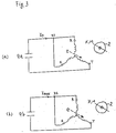
- Fig. 3(a) and Fig. 3(b) depict magnetizing of the fourth exemplary embodiment of the present invention.
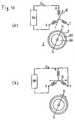
- Fig. 4(a) and Fig. 4(b) depict magnetizing of the fifth exemplary embodiment of the present invention.
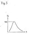
- Fig. 5 shows a waveform of magnetizing current.
- Fig. 6 depicts a low reluctance axis X and a magnetizing axis M of a four-pole-reluctance-magnet-motor used in the first and second exemplary embodiments of the present invention.
- Fig. 7 depicts a distribution of positioning current in the stator slots, stator field E and the rotor 2 positioned at the magnetized position of the four-pole-reluctance-magnet-motor used in the first exemplary embodiment of the present invention.
- Fig. 8 depicts a distribution of magnetizing current in the stator slots and magnetizing filed G of the four-pole-reluctance magnet-motor used in the first exemplary embodiment.
- Fig. 9 depicts the low reluctance axis X and the magnetizing axis M of the four-pole-reluctance-magnet-motor used in the fourth and fifth exemplary embodiments of the present invention.
- FIG. 10(a) and Fig. 10(b) depict the prior art.
- a reluctance magnet motor which is driven by both of magnet torque and reluctance torque has been widely known.
- Fig. 6 depicts a four-pole-reluctance-magnet-motor.
- a rotor 2 comprises the following elements:
- the first exemplary embodiment of the present invention has the physical structure shown in Fig. 6 and electrical structure depicted in Fig. 1(a) and Fig. 1(b).
- outer terminals R and S of Y connected three-phase stator coil are coupled together, thereby forming an outer terminal RS.
- the positioning current Ip is fed from the positioning power supply 9a to both the outer terminals RS and T.
- the stator field E is produced.
- the rotor 2 is driven to rotate by the reluctance torque generated between the low reluctance axis X and the stator field E, and the rotor 2 is positioned at the magnetizing position where the low reluctance axis X agrees with the stator field E.
- Fig. 7 depicts a distribution of the positioning current in the stator slot, the stator field E, and the rotor 2 positioned at the magnetizing position, where a shaft holding means (not shown) firmly holds the rotating shaft of rotor 2 in order to avoid moving when being magnetized.
- the outer terminal RS is separated into the independent terminals R and S, and the magnetizing current Imax having a waveform as shown in Fig.
- Fig. 8 depicts a distribution of magnetizing current in the stator slot and magnetizing field G.
- the motor used in the second exemplary embodiment of the present invention is the same one used in the previous exemplary embodiment.
- the positioning current Ip is fed between the outer terminals R and S from the positioning power source 9a, thereby producing stator field E.
- the rotor 2 is driven to rotate by the reluctance torque produced between the low reluctance axis X and the stator field E.
- the rotor 2 then, is positioned at the magnetizing position where the low reluctance axis X agrees with the stator field E. At this magnetizing position, the rotating shaft of the rotor 2 is firmly held by the shaft holding means (not shown) in order to avoid moving.
- the shaft holding means not shown
- the outer terminals R and S are coupled to form the outer terminal RS, and the magnetizing current Imax is fed between the outer terminals RS and T from the magnetizing power supply 9b.
- the magnetizing filed G is produced.
- the rotor 2 firmly held at the magnetized position is magnetized by the magnetizing field G along the magnetizing axis M which is 90 electrical degrees deference from the low reluctance axis X by the magnetizing field G.
- reluctance torque is impulsively generated in magnetizing. This reluctance torque should be reduced, for it may damage the rotor.
- weak magnetizing is carried out with weak magnetizing current before the normal magnetizing in order to reduce said reluctance torque. In the normal magnetizing after the weak magnetizing, attracting force between the magnetizing current and the rotor magnet which has been weak magnetized works against the rotation of rotor, and thereby reducing said reluctance torque.
- Tr ⁇ Isin2 ⁇ (electrical angle) is a deviation of rotor and the magnetizing position, and Tr represents the reluctance torque, and I represents stator current.
- the reluctance torque is proportional to the squared stator current, therefore, when using a half of normal magnetizing current for weak magnetizing, said reluctance torque is reduced to a quarter of the normal one.
- the rotor magnet is weakly magnetized by magnetic flux . In the normal magnetizing after the weak magnetizing, the rotor magnet produces magnet torque Tm against the reluctance torque. Tm ⁇ ⁇ Isin ⁇
- the torque applied to the rotor in the normal magnetizing is reduced by Tm.
- Repeated weak magnetizing by increasing the magnetizing current step by step is more effective for reducing said reluctance torque.
- the fourth exemplary embodiment of the present invention has a physical structure shown in Fig. 9 where the unmagnetized rotor magnet 3c is adhered on the rotor core 2a.
- Fig. 9 depicts, the low reluctance X axis of the rotor agrees with the magnetizing axis M.
- the outer terminals R and S of stator coil are coupled together, thereby forming the outer terminal RS.
- the positioning current Ip is fed from the positioning power supply 9a to both the outer terminals RS and T. As a result, the stator field E is produced.
- the rotor 2 is driven to rotate by the reluctance torque generated between the low reluctance axis X and the stator field E, and the rotor 2 is positioned at the magnetizing position where the low reluctance axis X agrees with the stator field E.
- Fig. 9 depicts a distribution of the positioning current in the stator slot, the stator field E, and the rotor 2 positioned at the magnetizing position, where a shaft holding means (not shown) firmly holds the rotating shaft of rotor 2 in order to avoid moving when being magnetized.
- the magnetizing current Imax is fed from the magnetizing power supply 9b to the outer terminals RS and T, thereby producing the magnetizing field G.
- the rotor 2 held at the magnetizing position is magnetized by the magnetizing field G along the magnetizing axis M whose direction agrees with the low reluctance axis X.
- the motor used in the fifth exemplary embodiment of the present invention is the same one used in the fourth exemplary embodiment.
- the positioning current Ip is fed between the outer terminal R and S from the positioning power source 9a, thereby producing stator field E.
- the rotor 2 is driven to rotate by the reluctance torque generated between the low reluctance axis X and the stator field E.
- the rotor 2 then, is positioned at the magnetizing position where the low reluctance axis X agrees with the stator field E. At this magnetizing position, the rotating shaft of the rotor 2 is firmly held by the shaft holding means (not shown) in order to avoid moving.
- the shaft holding means not shown
- the magnetizing current Imax is fed between the outer terminals R and S from the magnetizing power supply 9b.
- the magnetizing filed G is produced.
- the rotor 2 firmly held at the magnetized position is magnetized by the magnetizing field G along the magnetizing axis M whose direction agrees with the low reluctance axis X.
Abstract
- (a) forming an outer terminal RS by coupling the outer terminals R and S, and feeding positioning current between the outer terminals RS and T for positioning the rotor at a magnetizing position with reluctance torque,
- (b) holding a rotating shaft of the rotor positioned at the magnetized position in order to avoid moving,
- (c) separating said outer terminal RS to the outer terminals R and S, and feeding magnetizing current between the outer terminals R and S for magnetizing the rotor magnet.
Description
- The present invention relates to a magnetizing method for a rotor magnet of a reluctance magnet motor. The magnetizing comprises two steps; first, feed electric current to a stator coil for positioning a rotor at a magnetizing position by a reluctance torque, and then, feed electric current to the stator coil for magnetizing a rotor magnet.
- Fig. 10 is one of the drawing of Japanese Patent Application (Publication No. S57-14261,) which depicts that the stator coil is used for both positioning and magnetizing the rotor. In this prior art, a magnetic pole which has been weakened by some accident is remagentized. A
rotor 2 comprises arotor core 2a, arotor magnet 3d made of permanent magnet, and a stainless tube 7 which prevents breakage of therotor magnet 3d due to centrifugal force. Since the reluctance of therotor 2 is equal in all radial directions, this motor generates only magnet torque, and does not generate reluctance torque. Therotor magnet 3d has weakened magnetic poles N and S. First, as shown in Fig. 10(a), positioning current Ip is fed from apositioning power supply 9a to outer terminals R and S of the stator, thereby generating stator field E, then therotor 2 is driven to rotate by magnet torque produced between the stator field E and the magnetic poles NS, and therotor 2 is positioned where the magnetic poles NS and the stator field E are oriented in the same direction. Next, as shown in Fig. 10(b), magnetizing current Im is fed from amagnetizing power supply 9b to the outer terminals T and S of the stator, thereby producing magnetized field G as stator field. Then, therotor 2 is remagnetized by the magnetizing field G while rotaing along the arrow mark driven by magnetic torque produced between the magnetized field G and the magnetic poles NS. The rotation of the rotor is utilized for widening a magnetizing width over the coil pitch of the stator winding. - The present invention provides a magnetizing method for a rotor magnet of a reluctance magnet motor. The magnetizing method comprises the following steps:
- (a) Feed positioning current to the stator coil so that the rotor can be positioned at the magnetizing position by reluctance torque.
- (b) Hold the rotor positioned at the magnetizing position in order to avoid moving.
- (c) Feed magnetizing current to the stator coil so that the rotor can be magnetized.
- The step (c) further includes weak magnetizing of the rotor with weak magnetizing current before normal magnetizing in order to prevent the rotor from damaging due to motor torque produced in magnetizing the rotor.
- Fig. 1(a) and Fig. 1(b) depict magnetizing of the first exemplary embodiment of the present invention.
- Fig. 2(a) and Fig. 2(b) depict magnetizing of the second exemplary embodiment of the present invention.
- Fig. 3(a) and Fig. 3(b) depict magnetizing of the fourth exemplary embodiment of the present invention.
- Fig. 4(a) and Fig. 4(b) depict magnetizing of the fifth exemplary embodiment of the present invention.
- Fig. 5 shows a waveform of magnetizing current.
- Fig. 6 depicts a low reluctance axis X and a magnetizing axis M of a four-pole-reluctance-magnet-motor used in the first and second exemplary embodiments of the present invention.
- Fig. 7 depicts a distribution of positioning current in the stator slots, stator field E and the
rotor 2 positioned at the magnetized position of the four-pole-reluctance-magnet-motor used in the first exemplary embodiment of the present invention. - Fig. 8 depicts a distribution of magnetizing current in the stator slots and magnetizing filed G of the four-pole-reluctance magnet-motor used in the first exemplary embodiment.
- Fig. 9 depicts the low reluctance axis X and the magnetizing axis M of the four-pole-reluctance-magnet-motor used in the fourth and fifth exemplary embodiments of the present invention.
- Fig. 10(a) and Fig. 10(b) depict the prior art.
- A reluctance magnet motor which is driven by both of magnet torque and reluctance torque has been widely known. Fig. 6 depicts a four-pole-reluctance-magnet-motor. A
rotor 2 comprises the following elements: - (a) a
rotor core 2a made of high permeability materials such as laminated iron plate, - (b)
unmagnetized rotor magnets rotor core 2a, and - (c) a rotating
shaft 6 fixed to therotor core 2a. Therotor magnets rotor 2 does not have uniform reluctance in this motor. The rotor reluctance viewed from the stator is minimum at a low reluctance axis X which is 90 electrical degrees deference from the magnetizing axis M, since the permeabilities of therotor magnets rotor core 2a. Reluctance torque is produced between the low reluctance axis X and the stator field. - The first exemplary embodiment of the present invention has the physical structure shown in Fig. 6 and electrical structure depicted in Fig. 1(a) and Fig. 1(b). As shown in Fig. 1(a), outer terminals R and S of Y connected three-phase stator coil are coupled together, thereby forming an outer terminal RS. The positioning current Ip is fed from the
positioning power supply 9a to both the outer terminals RS and T. As a result, the stator field E is produced. Therotor 2 is driven to rotate by the reluctance torque generated between the low reluctance axis X and the stator field E, and therotor 2 is positioned at the magnetizing position where the low reluctance axis X agrees with the stator field E. Fig. 7 depicts a distribution of the positioning current in the stator slot, the stator field E, and therotor 2 positioned at the magnetizing position, where a shaft holding means (not shown) firmly holds the rotating shaft ofrotor 2 in order to avoid moving when being magnetized. Next, as shown in Fig. 1(b), the outer terminal RS is separated into the independent terminals R and S, and the magnetizing current Imax having a waveform as shown in Fig. 5 is fed from themagnetizing power supply 9b to the outer terminals R and S, thereby producing the magnetizing filed G. Therotor 2 held at the magnetizing position is magnetized by the magnetizing field G along the magnetizing axis M, which is 90 electrical degrees deference from the low reluctance axis X. Fig. 8 depicts a distribution of magnetizing current in the stator slot and magnetizing field G. - The motor used in the second exemplary embodiment of the present invention is the same one used in the previous exemplary embodiment. First, as shown in Fig. 2(a), the positioning current Ip is fed between the outer terminals R and S from the
positioning power source 9a, thereby producing stator field E. Therotor 2 is driven to rotate by the reluctance torque produced between the low reluctance axis X and the stator field E. Therotor 2, then, is positioned at the magnetizing position where the low reluctance axis X agrees with the stator field E. At this magnetizing position, the rotating shaft of therotor 2 is firmly held by the shaft holding means (not shown) in order to avoid moving. Next, as shown in Fig. 2(b), the outer terminals R and S are coupled to form the outer terminal RS, and the magnetizing current Imax is fed between the outer terminals RS and T from themagnetizing power supply 9b. As a result, the magnetizing filed G is produced. Therotor 2 firmly held at the magnetized position is magnetized by the magnetizing field G along the magnetizing axis M which is 90 electrical degrees deference from the low reluctance axis X by the magnetizing field G. - In the above embodiments, when the electrical angle difference between the low reluctance axis X and magnetizing axis M is deviated from 90 electrical degrees due to some cause, such as ununiform distribution of reluctance, reluctance torque is impulsively generated in magnetizing. This reluctance torque should be reduced, for it may damage the rotor. In the third exemplary embodiment of the present invention, weak magnetizing is carried out with weak magnetizing current before the normal magnetizing in order to reduce said reluctance torque. In the normal magnetizing after the weak magnetizing, attracting force between the magnetizing current and the rotor magnet which has been weak magnetized works against the rotation of rotor, and thereby reducing said reluctance torque. The effect of the weak magnetizing using a half of magnetizing current is described as follows:

- The reluctance torque is proportional to the squared stator current, therefore, when using a half of normal magnetizing current for weak magnetizing, said reluctance torque is reduced to a quarter of the normal one. The rotor magnet is weakly magnetized by magnetic flux . In the normal magnetizing after the weak magnetizing, the rotor magnet produces magnet torque Tm against the reluctance torque.

- Accordingly, the torque applied to the rotor in the normal magnetizing is reduced by Tm. Repeated weak magnetizing by increasing the magnetizing current step by step is more effective for reducing said reluctance torque.
- The fourth exemplary embodiment of the present invention has a physical structure shown in Fig. 9 where the unmagnetized rotor magnet 3c is adhered on the
rotor core 2a. As Fig. 9 depicts, the low reluctance X axis of the rotor agrees with the magnetizing axis M. First, as shown in Fig. 3(a), the outer terminals R and S of stator coil are coupled together, thereby forming the outer terminal RS. The positioning current Ip is fed from thepositioning power supply 9a to both the outer terminals RS and T. As a result, the stator field E is produced. Therotor 2 is driven to rotate by the reluctance torque generated between the low reluctance axis X and the stator field E, and therotor 2 is positioned at the magnetizing position where the low reluctance axis X agrees with the stator field E. Fig. 9 depicts a distribution of the positioning current in the stator slot, the stator field E, and therotor 2 positioned at the magnetizing position, where a shaft holding means (not shown) firmly holds the rotating shaft ofrotor 2 in order to avoid moving when being magnetized. Next, as shown in Fig. 3(b), the magnetizing current Imax is fed from the magnetizingpower supply 9b to the outer terminals RS and T, thereby producing the magnetizing field G. Therotor 2 held at the magnetizing position is magnetized by the magnetizing field G along the magnetizing axis M whose direction agrees with the low reluctance axis X. - The motor used in the fifth exemplary embodiment of the present invention is the same one used in the fourth exemplary embodiment. First, as shown in Fig. 4(a), the positioning current Ip is fed between the outer terminal R and S from the
positioning power source 9a, thereby producing stator field E. Therotor 2 is driven to rotate by the reluctance torque generated between the low reluctance axis X and the stator field E. Therotor 2, then, is positioned at the magnetizing position where the low reluctance axis X agrees with the stator field E. At this magnetizing position, the rotating shaft of therotor 2 is firmly held by the shaft holding means (not shown) in order to avoid moving. Next, as shown in Fig. 4(b), the magnetizing current Imax is fed between the outer terminals R and S from the magnetizingpower supply 9b. As a result, the magnetizing filed G is produced. Therotor 2 firmly held at the magnetized position is magnetized by the magnetizing field G along the magnetizing axis M whose direction agrees with the low reluctance axis X.
Claims (8)
- A magnetizing method for a rotor magnet of a reluctance magnet motor having a stator and a rotor, said stator including a Y connected of three-phase stator coil which has outer terminals R, S and T, and said rotor comprising a magnetizing axis of the rotor magnet and a low reluctance axis which is 90 electrical degrees difference from the magnetizing axis,
said magnetizing method comprising the steps of:(a) forming an outer terminal RS by coupling the outer terminals R and S, and feeding positioning current between the outer terminals RS and T for positioning the rotor at a magnetizing position by a reluctance torque,(b) holding a rotating shaft of the rotor positioned at the magnetizing position in order to avoid moving,(c) separating said outer terminal RS to the outer terminals R and S, and feeding magnetizing current between the outer terminals R and S for magnetizing the rotor magnet. - A magnetizing method for a rotor magnet of a reluctance magnet motor having a stator and a rotor, said stator including a Y connected three-phase stator coil which has outer terminals R, S and T, and said rotor comprising a magnetizing axis of the rotor magnet and a low reluctance axis which is 90 electrical degrees difference from the magnetizing axis,
said magnetizing method comprising the steps of:(a) feeding positioning current between the outer terminals R and S for positioning the rotor at a magnetizing position by a reluctance torque,(b) holding a rotating shaft of the rotor positioned at the magnetizing position in order to avoid moving,(c) coupling the outer terminals R and S to form the outer terminal RS, and feeding magnetizing current between the outer terminals RS and T for magnetizing the rotor magnet. - The magnetizing method of Claim 1, wherein Step (c) includes normal magnetizing of the rotor magnet by normal magnetizing current and weak magnetizing before the normal magnetizing by weak maganetizing current which is weaker than the normal magnetizing current.
- The magnetizing method of Claim 3, wherein the weak magnetizing of the rotor magnet is repeated by increasing the magnetizing current step by step before the normal magnetizing.
- The magnetizing method of Claim 2, wherein Step (c) includes normal magnetizing of the rotor magnet by normal magnetizing current and weak magnetizing before the normal magnetizing current by weak magnetizing current which is weaker than the normal magnetizing current.
- The magnetizing method of Claim 5, wherein the weak magnetizing of the rotor magnet is repeated by increasing the magnetizing current step by step before the normal magnetizing.
- A magnetizing method for a rotor magnet of a reluctance magnet motor having a stator and a rotor, said stator including a Y connected three-phase stator coil which has outer terminals R, S and T, and said rotor comprising a magnetizing axis of the rotor magnet and a low reluctance axis which agrees with the magnetizing axis,
said magnetizing method comprising the steps of:(a) forming an outer terminal RS by coupling the outer terminals R and S, and feeding positioning current between the outer terminals RS and T for positioning the rotor at a magnetizing position by a reluctance torque,(b) holding a rotating shaft of the rotor positioned at the magnetized position in order to avoid moving,(c) feeding magnetizing current between the outer terminals RS and T for magnetizing the rotor magnet. - A magnetizing method for a rotor magnet of a reluctance magnet motor having a stator and a rotor, said stator including a Y connected three-phase stator coil which has outer terminals R, S and T, and said rotor comprising a magnetizing axis of the rotor magnet and a low reluctance axis which agrees with the magnetizing axis,
said magnetizing method comprising the steps of:(a) feeding positioning current between the outer terminals R and S for positioning the rotor at a magnetizing position by a reluctance torque,(b) holding a rotating shaft of the rotor positioned at the magnetized position in order to avoid moving,(c) feeding magnetizing current between the outer terminals R and S for magnetizing the rotor magnet.
Applications Claiming Priority (3)
| Application Number | Priority Date | Filing Date | Title |
|---|---|---|---|
| JP51720/96 | 1996-03-08 | ||
| JP5172096 | 1996-03-08 | ||
| JP05172096A JP3686153B2 (en) | 1996-03-08 | 1996-03-08 | Magnetization method of permanent magnet motor |
Publications (2)
| Publication Number | Publication Date |
|---|---|
| EP0800257A1 true EP0800257A1 (en) | 1997-10-08 |
| EP0800257B1 EP0800257B1 (en) | 2000-09-20 |
Family
ID=12894734
Family Applications (1)
| Application Number | Title | Priority Date | Filing Date |
|---|---|---|---|
| EP97103552A Expired - Lifetime EP0800257B1 (en) | 1996-03-08 | 1997-03-04 | Magnetizing method for rotor magnet of reluctance magnet motor |
Country Status (6)
| Country | Link |
|---|---|
| US (1) | US6101081A (en) |
| EP (1) | EP0800257B1 (en) |
| JP (1) | JP3686153B2 (en) |
| CN (1) | CN1084074C (en) |
| DE (1) | DE69703131T2 (en) |
| MY (1) | MY117998A (en) |
Cited By (3)
| Publication number | Priority date | Publication date | Assignee | Title |
|---|---|---|---|---|
| WO1999035729A2 (en) * | 1997-12-29 | 1999-07-15 | Empresa Brasileira De Compressores S.A. - Embraco | A process for magnetizing the permanent magnets of an electric motor rotor and a process for assembling a hermetic compressor motor |
| WO2004034553A1 (en) * | 2002-10-11 | 2004-04-22 | Emerson Electric Co. | Apparatus and method of using the stator coils of an electric motor to magnetize permanent magnets of the motor rotor when the span of each stator coil is smaller than the width of each permanent magnet pole |
| WO2009077258A1 (en) | 2007-12-18 | 2009-06-25 | Robert Bosch Gmbh | Method for the sensorless operation of an electric, electronically commutating machine |
Families Citing this family (3)
| Publication number | Priority date | Publication date | Assignee | Title |
|---|---|---|---|---|
| US20060103254A1 (en) * | 2004-11-16 | 2006-05-18 | Horst Gary E | Permanent magnet rotor |
| WO2015181968A1 (en) * | 2014-05-30 | 2015-12-03 | 日産自動車株式会社 | Method for manufacturing permanent-magnet-type electric motor |
| CN109474156B (en) * | 2018-12-29 | 2023-09-05 | 湖南开启时代科技股份有限公司 | Three-phase winding simultaneous power supply type rotor axial magnetization switch reluctance motor |
Citations (2)
| Publication number | Priority date | Publication date | Assignee | Title |
|---|---|---|---|---|
| FR1277335A (en) * | 1960-10-17 | 1961-12-01 | Cie Crouzet | Method and device for magnetizing magnetic parts, in particular made of hypercoercive magnetic materials, which must have alternating magnetic poles, 'close and close to each other and magnets thus obtained |
| US5200729A (en) * | 1989-08-29 | 1993-04-06 | Yamamoto Electric Corporation | Permanent magnet and magnetization apparatus for producing the permanent magnet |
Family Cites Families (5)
| Publication number | Priority date | Publication date | Assignee | Title |
|---|---|---|---|---|
| JPS575313A (en) * | 1980-06-12 | 1982-01-12 | Matsushita Electric Ind Co Ltd | Magnetizing method for magnet |
| JPS57142165A (en) * | 1981-02-26 | 1982-09-02 | Hitachi Ltd | Method and device for magnetizing permanent magnet rotary electric machine |
| JPS6323541A (en) * | 1986-03-05 | 1988-01-30 | Hitachi Ltd | Magnetization of motor |
| DE68914240T2 (en) * | 1988-10-21 | 1994-10-27 | Sony Corp | Optical waveguide and generator for generating the second harmonic. |
| JPH06253508A (en) * | 1992-12-28 | 1994-09-09 | Toshiba Corp | Magnetizing method for permanent magnet electric rotating machine |
-
1996
- 1996-03-08 JP JP05172096A patent/JP3686153B2/en not_active Expired - Fee Related
-
1997
- 1997-03-04 EP EP97103552A patent/EP0800257B1/en not_active Expired - Lifetime
- 1997-03-04 DE DE69703131T patent/DE69703131T2/en not_active Expired - Fee Related
- 1997-03-05 MY MYPI97000912A patent/MY117998A/en unknown
- 1997-03-06 US US08/812,812 patent/US6101081A/en not_active Expired - Fee Related
- 1997-03-07 CN CN97103129A patent/CN1084074C/en not_active Expired - Fee Related
Patent Citations (2)
| Publication number | Priority date | Publication date | Assignee | Title |
|---|---|---|---|---|
| FR1277335A (en) * | 1960-10-17 | 1961-12-01 | Cie Crouzet | Method and device for magnetizing magnetic parts, in particular made of hypercoercive magnetic materials, which must have alternating magnetic poles, 'close and close to each other and magnets thus obtained |
| US5200729A (en) * | 1989-08-29 | 1993-04-06 | Yamamoto Electric Corporation | Permanent magnet and magnetization apparatus for producing the permanent magnet |
Non-Patent Citations (1)
| Title |
|---|
| PATENT ABSTRACTS OF JAPAN * |
Cited By (8)
| Publication number | Priority date | Publication date | Assignee | Title |
|---|---|---|---|---|
| WO1999035729A2 (en) * | 1997-12-29 | 1999-07-15 | Empresa Brasileira De Compressores S.A. - Embraco | A process for magnetizing the permanent magnets of an electric motor rotor and a process for assembling a hermetic compressor motor |
| WO1999035729A3 (en) * | 1997-12-29 | 1999-09-16 | Brasil Compressores Sa | A process for magnetizing the permanent magnets of an electric motor rotor and a process for assembling a hermetic compressor motor |
| US6380654B1 (en) | 1997-12-29 | 2002-04-30 | Empresa Brasileira De Compressores S.A. -Embraco | Process for magnetizing the permanent magnets of an electric motor rotor and a process for assembling a hermetic compressor motor |
| WO2004034553A1 (en) * | 2002-10-11 | 2004-04-22 | Emerson Electric Co. | Apparatus and method of using the stator coils of an electric motor to magnetize permanent magnets of the motor rotor when the span of each stator coil is smaller than the width of each permanent magnet pole |
| US6903640B2 (en) | 2002-10-11 | 2005-06-07 | Emerson Electric Co. | Apparatus and method of using the stator coils of an electric motor to magnetize permanent magnets of the motor rotor when the span of each stator coil is smaller than the width of each permanent magnet pole |
| WO2009077258A1 (en) | 2007-12-18 | 2009-06-25 | Robert Bosch Gmbh | Method for the sensorless operation of an electric, electronically commutating machine |
| CN101903785A (en) * | 2007-12-18 | 2010-12-01 | 罗伯特.博世有限公司 | Method for the sensorless operation of an electric, electronically commutating machine |
| CN101903785B (en) * | 2007-12-18 | 2014-09-17 | 罗伯特.博世有限公司 | Method for the sensorless operation of an electric, electronically commutating machine |
Also Published As
| Publication number | Publication date |
|---|---|
| US6101081A (en) | 2000-08-08 |
| JPH09247909A (en) | 1997-09-19 |
| MY117998A (en) | 2004-08-30 |
| CN1164772A (en) | 1997-11-12 |
| DE69703131T2 (en) | 2001-03-01 |
| EP0800257B1 (en) | 2000-09-20 |
| DE69703131D1 (en) | 2000-10-26 |
| CN1084074C (en) | 2002-05-01 |
| JP3686153B2 (en) | 2005-08-24 |
Similar Documents
| Publication | Publication Date | Title |
|---|---|---|
| US4454438A (en) | Synchronized induction motor | |
| KR100234587B1 (en) | Dc brushless motor and controller | |
| US4388545A (en) | Rotor for a permanent magnet AC motor | |
| EP0740397B1 (en) | Stator structure for rotary electric machine | |
| EP1708341A2 (en) | System and method for magnetization of permanent magnet rotors in electrical machines | |
| EP0160868A2 (en) | Brushless motor | |
| EP1717929B1 (en) | Method for magnetizing magnetic bodies of a rotor for dynamo-electric machine | |
| EP0237935B1 (en) | Permanent magnet field dc machine | |
| US20070007842A1 (en) | Self magnetizing motor and stator thereof | |
| CN100495869C (en) | Tangential magnet steel mixed excitation synchronous machine possessing divided magnetic circuit | |
| EP0800257B1 (en) | Magnetizing method for rotor magnet of reluctance magnet motor | |
| US20100295401A1 (en) | Motor and device using the same | |
| EP0215441A2 (en) | Miniature electric rotating machine | |
| JPH05236684A (en) | Brushless cd motor | |
| Rabinovici | Magnetic field analysis of permanent magnet motors | |
| JP2021083221A (en) | IPM rotor manufacturing method | |
| JPH05236686A (en) | Brushless cd motor | |
| KR100373427B1 (en) | A magnet type motor and generator | |
| US3078381A (en) | Permanent magnet rotor for a dynamoelectric machine | |
| JPH10164784A (en) | Magnet rotor | |
| JPH0638474A (en) | Magnetizing method for rotor of brushless motor and magnetizing jig | |
| JPS629202B2 (en) | ||
| KR100479080B1 (en) | Line-Started Permanent Magnet Motor | |
| JP2003018774A (en) | Dc brushless motor | |
| JP4714445B2 (en) | Magnetization method and apparatus for permanent magnet motor |
Legal Events
| Date | Code | Title | Description |
|---|---|---|---|
| PUAI | Public reference made under article 153(3) epc to a published international application that has entered the european phase |
Free format text: ORIGINAL CODE: 0009012 |
|
| AK | Designated contracting states |
Kind code of ref document: A1 Designated state(s): DE FR GB |
|
| 17P | Request for examination filed |
Effective date: 19971114 |
|
| GRAG | Despatch of communication of intention to grant |
Free format text: ORIGINAL CODE: EPIDOS AGRA |
|
| 17Q | First examination report despatched |
Effective date: 19990727 |
|
| GRAG | Despatch of communication of intention to grant |
Free format text: ORIGINAL CODE: EPIDOS AGRA |
|
| GRAH | Despatch of communication of intention to grant a patent |
Free format text: ORIGINAL CODE: EPIDOS IGRA |
|
| GRAH | Despatch of communication of intention to grant a patent |
Free format text: ORIGINAL CODE: EPIDOS IGRA |
|
| GRAA | (expected) grant |
Free format text: ORIGINAL CODE: 0009210 |
|
| AK | Designated contracting states |
Kind code of ref document: B1 Designated state(s): DE FR GB |
|
| REF | Corresponds to: |
Ref document number: 69703131 Country of ref document: DE Date of ref document: 20001026 |
|
| ET | Fr: translation filed | ||
| PLBE | No opposition filed within time limit |
Free format text: ORIGINAL CODE: 0009261 |
|
| STAA | Information on the status of an ep patent application or granted ep patent |
Free format text: STATUS: NO OPPOSITION FILED WITHIN TIME LIMIT |
|
| 26N | No opposition filed | ||
| REG | Reference to a national code |
Ref country code: GB Ref legal event code: IF02 |
|
| PGFP | Annual fee paid to national office [announced via postgrant information from national office to epo] |
Ref country code: GB Payment date: 20080227 Year of fee payment: 12 |
|
| PGFP | Annual fee paid to national office [announced via postgrant information from national office to epo] |
Ref country code: FR Payment date: 20080311 Year of fee payment: 12 Ref country code: DE Payment date: 20080228 Year of fee payment: 12 |
|
| GBPC | Gb: european patent ceased through non-payment of renewal fee |
Effective date: 20090304 |
|
| REG | Reference to a national code |
Ref country code: FR Ref legal event code: ST Effective date: 20091130 |
|
| PG25 | Lapsed in a contracting state [announced via postgrant information from national office to epo] |
Ref country code: DE Free format text: LAPSE BECAUSE OF NON-PAYMENT OF DUE FEES Effective date: 20091001 |
|
| PG25 | Lapsed in a contracting state [announced via postgrant information from national office to epo] |
Ref country code: GB Free format text: LAPSE BECAUSE OF NON-PAYMENT OF DUE FEES Effective date: 20090304 Ref country code: FR Free format text: LAPSE BECAUSE OF NON-PAYMENT OF DUE FEES Effective date: 20091123 |