EP0799709B1 - Image forming apparatus with controlled access - Google Patents
Image forming apparatus with controlled access Download PDFInfo
- Publication number
- EP0799709B1 EP0799709B1 EP97302330A EP97302330A EP0799709B1 EP 0799709 B1 EP0799709 B1 EP 0799709B1 EP 97302330 A EP97302330 A EP 97302330A EP 97302330 A EP97302330 A EP 97302330A EP 0799709 B1 EP0799709 B1 EP 0799709B1
- Authority
- EP
- European Patent Office
- Prior art keywords
- access control
- forming apparatus
- image forming
- mode
- printer
- Prior art date
- Legal status (The legal status is an assumption and is not a legal conclusion. Google has not performed a legal analysis and makes no representation as to the accuracy of the status listed.)
- Expired - Lifetime
Links
- 238000000034 method Methods 0.000 claims description 6
- 230000001419 dependent effect Effects 0.000 claims 1
- 239000004020 conductor Substances 0.000 description 12
- 230000008859 change Effects 0.000 description 4
- 230000008901 benefit Effects 0.000 description 3
- 230000001276 controlling effect Effects 0.000 description 3
- 230000000694 effects Effects 0.000 description 2
- 230000006978 adaptation Effects 0.000 description 1
- 230000000881 depressing effect Effects 0.000 description 1
- 238000005516 engineering process Methods 0.000 description 1
- 230000006870 function Effects 0.000 description 1
- 230000004048 modification Effects 0.000 description 1
- 238000012986 modification Methods 0.000 description 1
- 230000008569 process Effects 0.000 description 1
- 230000009467 reduction Effects 0.000 description 1
- 230000001105 regulatory effect Effects 0.000 description 1
Images

Classifications
-
- B—PERFORMING OPERATIONS; TRANSPORTING
- B41—PRINTING; LINING MACHINES; TYPEWRITERS; STAMPS
- B41J—TYPEWRITERS; SELECTIVE PRINTING MECHANISMS, i.e. MECHANISMS PRINTING OTHERWISE THAN FROM A FORME; CORRECTION OF TYPOGRAPHICAL ERRORS
- B41J2/00—Typewriters or selective printing mechanisms characterised by the printing or marking process for which they are designed
- B41J2/485—Typewriters or selective printing mechanisms characterised by the printing or marking process for which they are designed characterised by the process of building-up characters or image elements applicable to two or more kinds of printing or marking processes
- B41J2/505—Typewriters or selective printing mechanisms characterised by the printing or marking process for which they are designed characterised by the process of building-up characters or image elements applicable to two or more kinds of printing or marking processes from an assembly of identical printing elements
- B41J2/5056—Typewriters or selective printing mechanisms characterised by the printing or marking process for which they are designed characterised by the process of building-up characters or image elements applicable to two or more kinds of printing or marking processes from an assembly of identical printing elements using dot arrays providing selective dot disposition modes, e.g. different dot densities for high speed and high-quality printing, array line selections for multi-pass printing, or dot shifts for character inclination
Definitions
- the present invention relates to image forming apparatus, and, more particularly, to printers having a controllable operation.
- An image forming apparatus such as a printer, may typically be selectively operated in one of a plurality of different modes.
- one such mode may be a high quality mode which provides a high quality print job.
- the ink jet printer may be operated in a relatively lower quality ink saver mode wherein certain available pixels are essentially "blocked out" such that ink is not deposited on the print medium at a corresponding location.
- the printer may similarly be operated in different modes to use different amounts of toner for a specific job.
- a paper-saving economy mode may result, for example, in multiple pages of image data being condensed and printed on a single sheet of paper, or a reduction of the quantity of paper available to a user.
- the printer is usually switched from one mode of operation to another by depressing a button on the printer, see e.g. EP-A-536 050, or alternatively sending a signal from an attached host computer to the printer.
- a button on the printer see e.g. EP-A-536 050
- Any person may either depress a button on the printer or send an appropriate signal from the host computer to the printer to switch from one mode of operation to another.
- a problem with known printers is that it is not possible to prevent a person from utilizing a printer in a mode of operation which consumes a relatively large amount of a consumable supply, such as ink, toner or paper, over a predetermined unit of time.
- a consumable supply such as ink, toner or paper
- a color ink jet printer attached to a host computer may be used primarily for producing business-type graphics, presentations, etc. Nonetheless, children may also have access to the printer and use the same for printing created artwork, clip art, etc.
- the activities associated with such print jobs provide children with entertainment and education, the person desiring to use the printer for business purposes may wish to limit use of the consumable supplies in the printer so that adequate consumable supplies are later available for the production of business-type work product.
- the present invention provides an image forming apparatus, such as a printer, having controlled access to selected features and/or (sub)systems.
- the controlled access allows a selected usage of consumable supplies, such as ink or toner.
- the invention comprises, in one form thereof, an image forming apparatus including a print engine operable in at least two modes, and an access control system connected to and controlling the print engine.
- the access control system includes an access control key for allowing selective and discriminate switching of the print engine from one of the at least two modes to an other of the at least two modes, such as from an economy mode to a high quality mode, or vice versa.
- An advantage of the present invention is that controlled access is provided to certain printer features and/or (sub)systems.
- Another advantage is that a consumption rate of consumable supplies, such as ink or toner, may be controlled.
- the access control system provides selective and discriminate access to selected features and/or (sub)systems of an image forming apparatus, such as a printer, and thereby is capable of controlling a rate of consumption of consumable supplies, such as ink, toner, paper, etc.
- One subsystem which may for example be controlled is access to a particular media source, such as a paper tray containing high quality paper stock, an envelope feeding attachment, etc.
- control may include the meaning of the terms “regulate”, “regulating”, etc. That is, such "control” may or may not include a feedback loop.
- control may or may not include a feedback loop.
- methodology and logic of the present invention described herein may be carried out using any number of structural configurations such as electronic hardware, software, and/or firmware, or the like.
- the access control system of the present invention requests and interfaces with an access control key to be provided by a user (block 10).
- the access control key can be in the form of an electronic access control key such as a password, or a mechanical access control key such as a turn key or coin. If the access control key interfaced with the printer by a user is valid (decision block 12 and line 14), then the user is allowed access to certain features and/or (sub)systems of the printer (block 16). On the other hand, if the access control key is not valid (line 18), then control passes back to block 10.
- Block 10, line 20, decision block 12 and line 18 therefore define a wait state during which the printer waits for a proper access control key to be interfaced therewith by a user.
- a user is allowed access to the printing system, as indicated by block 16, then certain features and/or (sub)systems of the printer may be accessed and modified.
- the printer may be switched from one mode of operation to another wherein the consumption rate of a consumable supply such as ink, toner or paper is changed. Since the printer also operates at a known throughput rate, the consumable supply may also be expressed in the form of a period of time which the printer may be operated.
- the control ends (block 22). The same logic as shown in Fig. 1 must again be followed if the mode of operation of the printer is to be changed.
- Fig. 2 is a schematic illustration of an embodiment of an access control system 30 of the present invention including an electronic access key.
- Access control system 30 includes a printer 32 which is connected to a host computer 34 via a conductor 36.
- Printer 32 includes a print engine 38 used for printing an image on a print medium such as paper (not shown).
- print engine 38 includes an ink jet cartridge or pen with a consumable supply of ink therein.
- print engine 38 includes an electrophotographic assembly with a consumable supply of toner for transferring a latent image to the print medium.
- Printer 32 also includes a processor 40 which is connected to and controls print engine 38 via a conductor 42.
- Processor 40 is connected to host computer 34 via line 36 and receives input data therefrom.
- printer 32 may also include other structures, not shown, such as a data buffer, etc.
- Printer 32 is operable in at least two modes of operation, such as an economy mode and a high quality mode.
- the economy mode of operation uses less of a consumable supply than the high quality mode.
- the consumable supply may be selectively chosen as corresponding to ink, toner, paper or time, as indicated above. Since the present invention does not directly relate to the consumable supply, but rather to a method and system for providing controlled access to a consumable supply, these consumable supplies are not shown in the drawings.
- the high quality mode may be a "shingled" or band interlaced mode in which the nozzles of an ink jet cartridge are selectively fired over multiple passes of the printhead across the print medium. Selected ones of the nozzles are fired during one pass of the printhead, while selected others of the nozzles are fired during another pass of the printhead.
- the basic concept of "shingling" is known in the art as providing a high quality print job.
- the economy mode for an ink jet printer may correspond to an ink saver mode in which only certain of the addressable pixels making up a print image are actually used during the printing process.
- the print image may be divided into a number of addressable pixels for deciding whether or not to jet an ink droplet onto the print medium at the particular addressable pixel.
- an ink saver mode only a predetermined array of the addressable pixels are actually utilized for jetting ink onto the print medium.
- One such known ink saver mode skips every other addressable pixel for jetting ink onto the print medium.
- Host computer 34 includes a display screen 44 on which textual information such as that shown in Fig. 2 may be displayed to a user. This may be accomplished with a software driver provided with the printer which is loaded onto the host computer.
- An electronic access control key in the form of a password request is displayed on screen 44 when a user desires to access the printer system to change the mode of operation thereof.
- a status indicator corresponding to the present mode of operation is also displayed on screen 44. In the embodiment shown in Fig. 2, the status indicator is displayed as a mode of operation for an economy mode or a high quality mode, although other modes of operation are also possible.
- the correct password can either be stored as an (encrypted) data file on the host computer or in a non-volatile (NV) RAM memory in printer 32.
- NV non-volatile
- the NV RAM memory in printer 32 may be incorporated into processor 40. If an appropriate password is entered into host computer 34, such as by using a keyboard, then an electrical signal is transmitted to processor 40 over conductor 36. The user is then allowed access to certain features and/or (sub)systems of the printer so that the printer may be changed from one operating mode to another.
- Fig. 3 illustrates a flow chart of access control system 30 shown in Fig. 2.
- the user desires access to a feature and/or (sub)system of printer 32 (block 50).
- the printer system requests an electronic access control key prior to allowing the printer feature and/or (sub)system to be accessed (block 52).
- the electronic key in Fig. 2 is in the form of a password request from the printer system.
- the password request can originate from either the software driver located on host computer 34 or processor 40 located in printer 32.
- a decision is then made as to whether the password is valid for access to the desired feature and/or (sub)system (decision block 54). If the result is NO (line 56), control passes back to block 52.
- the user is allowed access to the printer feature and/or (sub)systems (block 60). For example, the user may change the mode of operation of printer 32 from an economy mode to a high quality mode, or vice versa.
- the printer feature and/or (sub)systems are locked out (block 62) and control passes back to block 50.
- the electronic access control key is in the form of a password entered into host computer 34.
- host computer 34 provides a corresponding electrical signal over conductor 36 to processor 40 of printer 32. Since the signal transmitted over conductor 36 to processor 40 corresponds to the password, it is also possible to define the electronic access control key as being the value of a particular electrical signal transmitted to processor 40.
- printer 74 includes a processor 76 which is connected to a print engine 78 via a conductor 80.
- Processor 76 and print engine 78 are similar in structure and function to processor 40 and print engine 38 described above with reference to Fig. 2.
- Processor 76 is also connected to a mechanical key input device 82 via a conductor 84.
- Mechanical key input device 82 includes a rotatable tumbler 86 which is movable between two positions corresponding to an economy mode and a high quality mode of printing.
- Mechanical access control key 72 which is in the form of a turn key in the embodiment shown, is insertable into slot 88 of tumbler 86. Tumbler 86 is in a position corresponding to the economy mode as shown in Fig. 4, and can also be rotated clockwise approximately 90 degrees to a position corresponding to the high quality mode of printer 74.
- Mechanical key input device 82 is configured to provide an output signal which is transmitted over conductor 84 to processor 76. The output signal is indicative of the selected mode of operation of printer 74.
- Processor 76 controls print engine 78 via conductor 80 to effect a desired mode of operation.
- Mechanical access control key 72 therefore provides selective and discriminate switching of print engine 78 from one mode of operation to another mode, such as from an economy mode to a high quality mode.
- Fig. 5 illustrates a flowchart for access control system 70 shown in Fig. 4.
- the user desires access to a feature and/or (sub)system of printer 70 (block 120).
- the printer system requests a mechanical access control key prior to allowing the printer feature and/or (sub)system to be accessed (block 122).
- the mechanical access key in Fig. 4 is in the form of a turn key which is inserted into slot 88 of mechanical key input device 82.
- a decision is then made as to whether the mechanical access key is valid for access to the desired feature and/or (sub)system (decision block 124). If the result is NO (line 126), control passes back to block 122.
- the user is allowed access to the printer feature and/or (sub)systems (block 130). For example, the user may change the mode of operation of printer 70 from an economy mode to a high quality mode, or vice versa. After the user is allowed access to the printer feature and/or (sub)systems, the printer feature and/or (sub)systems are locked out (block 132) and control passes back to block 120.
- Fig. 6 schematically illustrates another embodiment of an access control system 100 of the present invention including a mechanical access control key 102 in the form of a coin.
- Coin 102 is interfaced with a coin input device 104 of a printer 106.
- Coin input device 104 is connected via conductor 108 to a processor 110 which in turn is connected via conductor 112 to print engine 114.
- Coin input device 104 includes appropriate mechanical sensors and circuitry (not shown) to determine a total monetary amount of coins 102 inserted into coin input device 104.
- the monetary value corresponding to the number of coins 102 inserted into coin input device 104 is used to determine when a feature and/or (sub)system of printer 106 may be accessed for use or modification.
- the monetary value of the number of coins 102 inserted into coin input device 104 can be used to control access to a mode of operation of the printer such as an economy mode or high quality mode, the total number of sheets which may be used, or a time period during which the printer may be used.
- the monetary value can also be used to allow a user to switch from one mode of operation to another during use, such as from an economy mode to a high quality mode, based on the monetary value remaining at the time a request to change the mode of operation is made.
- the mechanical access control key is in the form of a turn key 72 and coin 102, respectively.
- other mechanical access control keys may also be utilized.
- Other examples may include a magnetically coded access card, or dip switches on the printer having limited access thereto.
- the access control system of the present invention has many possible applications. For example, a parent may wish to limit the amount of consumable supplies which a child is allowed to use. Moreover, a technology administrator for a business may wish to control which persons in the business are allowed to use the printer in a specific mode of operation. Further, it is possible that hotels may place a computer and printer within a room for use by a patron. The printer could be locked out of operation unless a specific access control key is entered by the patron. Other uses are also possible.
- host computer 34 is directly connected to printer 32 via conductor 36, such as a parallel or serial cable.
- printer 32 may be connected to and controlled by a computer which is not directly attached thereto.
- LAN local area network
- printer 32 may be connected to and controlled by a computer which is not directly attached thereto.
- it may be desirable to control printer 32 over a local area network (LAN).
- LAN local area network
- a tone generating chip such as found in a conventional telephone to access a remotely located system including a tone demodulation circuit for entering a pass code allowing a feature and/or (sub)system of a printer located at the remote station to be accessed (similar to accessing an electronic voice mail system using a touch tone telephone).
Description
- The present invention relates to image forming apparatus, and, more particularly, to printers having a controllable operation.
- An image forming apparatus, such as a printer, may typically be selectively operated in one of a plurality of different modes. In the case of an ink jet printer, one such mode may be a high quality mode which provides a high quality print job. Alternatively, the ink jet printer may be operated in a relatively lower quality ink saver mode wherein certain available pixels are essentially "blocked out" such that ink is not deposited on the print medium at a corresponding location. In the case of an electrophotographic printer (e.g., a laser printer), the printer may similarly be operated in different modes to use different amounts of toner for a specific job.
- Also, a paper-saving economy mode may result, for example, in multiple pages of image data being condensed and printed on a single sheet of paper, or a reduction of the quantity of paper available to a user.
- With conventional printers, the printer is usually switched from one mode of operation to another by depressing a button on the printer, see e.g. EP-A-536 050, or alternatively sending a signal from an attached host computer to the printer. With such known printers, however, there is no controlled access to the printer for switching from one mode of operation to another. Any person may either depress a button on the printer or send an appropriate signal from the host computer to the printer to switch from one mode of operation to another.
- A problem with known printers is that it is not possible to prevent a person from utilizing a printer in a mode of operation which consumes a relatively large amount of a consumable supply, such as ink, toner or paper, over a predetermined unit of time. For example, a color ink jet printer attached to a host computer may be used primarily for producing business-type graphics, presentations, etc. Nonetheless, children may also have access to the printer and use the same for printing created artwork, clip art, etc. Although the activities associated with such print jobs provide children with entertainment and education, the person desiring to use the printer for business purposes may wish to limit use of the consumable supplies in the printer so that adequate consumable supplies are later available for the production of business-type work product.
- What is needed in the art is an image forming apparatus, such as a printer, which allows controlled access to selected features and/or (sub)systems of the printer.
- The present invention provides an image forming apparatus, such as a printer, having controlled access to selected features and/or (sub)systems. The controlled access allows a selected usage of consumable supplies, such as ink or toner.
- The invention comprises, in one form thereof, an image forming apparatus including a print engine operable in at least two modes, and an access control system connected to and controlling the print engine. The access control system includes an access control key for allowing selective and discriminate switching of the print engine from one of the at least two modes to an other of the at least two modes, such as from an economy mode to a high quality mode, or vice versa.
- An advantage of the present invention is that controlled access is provided to certain printer features and/or (sub)systems.
- Another advantage is that a consumption rate of consumable supplies, such as ink or toner, may be controlled.
- The above-mentioned and other features and advantages of this invention, and the manner of attaining them, will become more apparent and the invention will be better understood by reference to the following description of embodiments of the invention given by way of example only and taken in conjunction with the accompanying drawings, wherein:
- Fig. 1 is a basic flowchart of an embodiment of the access control system of the present invention;
- Fig. 2 is a schematic illustration of an embodiment of an access control system of the present invention including an electronic access key;
- Fig. 3 is a flowchart of the access control system shown in Fig. 2;
- Fig. 4 is a schematic illustration of an embodiment of an access control system of the present invention including a mechanical access key;
- Fig. 5 is a flowchart of the access control system shown in Fig. 4; and
- Fig. 6 is a schematic illustration of an embodiment of an access control system of the present invention with another variant of a mechanical access key.
-
- Corresponding reference characters indicate corresponding parts throughout the several views. The exemplifications set out herein illustrate one preferred embodiment of the invention, in one form, and such exemplifications are not to be construed as limiting the scope of the invention in any manner.
- Referring now to the drawings and particularly to Fig. 1, there is shown a basic flowchart of an embodiment of an access control system of the present invention. The access control system provides selective and discriminate access to selected features and/or (sub)systems of an image forming apparatus, such as a printer, and thereby is capable of controlling a rate of consumption of consumable supplies, such as ink, toner, paper, etc. One subsystem which may for example be controlled is access to a particular media source, such as a paper tray containing high quality paper stock, an envelope feeding attachment, etc.
- Where in this application the terms "control", "controlling" or the like are used, it is to be understood that such terms may include the meaning of the terms "regulate", "regulating", etc. That is, such "control" may or may not include a feedback loop. Moreover, it is also to be understood, and it will be appreciated by those skilled in the art, that the methodology and logic of the present invention described herein may be carried out using any number of structural configurations such as electronic hardware, software, and/or firmware, or the like.
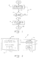
- In contrast with a conventional printer which simply accepts a received signal and switches from one mode of operation to another, the access control system of the present invention requests and interfaces with an access control key to be provided by a user (block 10). As will be described in more detail hereinafter, the access control key can be in the form of an electronic access control key such as a password, or a mechanical access control key such as a turn key or coin. If the access control key interfaced with the printer by a user is valid (
decision block 12 and line 14), then the user is allowed access to certain features and/or (sub)systems of the printer (block 16). On the other hand, if the access control key is not valid (line 18), then control passes back toblock 10.Block 10,line 20,decision block 12 andline 18 therefore define a wait state during which the printer waits for a proper access control key to be interfaced therewith by a user. - If a user is allowed access to the printing system, as indicated by
block 16, then certain features and/or (sub)systems of the printer may be accessed and modified. For example, the printer may be switched from one mode of operation to another wherein the consumption rate of a consumable supply such as ink, toner or paper is changed. Since the printer also operates at a known throughput rate, the consumable supply may also be expressed in the form of a period of time which the printer may be operated. After accessing the printing system, and changing a mode of operation (if desired), the control ends (block 22). The same logic as shown in Fig. 1 must again be followed if the mode of operation of the printer is to be changed. - Fig. 2 is a schematic illustration of an embodiment of an
access control system 30 of the present invention including an electronic access key.Access control system 30 includes aprinter 32 which is connected to ahost computer 34 via aconductor 36.Printer 32 includes aprint engine 38 used for printing an image on a print medium such as paper (not shown). In the case of an ink jet printer,print engine 38 includes an ink jet cartridge or pen with a consumable supply of ink therein. In the case of a laser printer,print engine 38 includes an electrophotographic assembly with a consumable supply of toner for transferring a latent image to the print medium. -
Printer 32 also includes aprocessor 40 which is connected to and controlsprint engine 38 via aconductor 42.Processor 40 is connected tohost computer 34 vialine 36 and receives input data therefrom. Of course,printer 32 may also include other structures, not shown, such as a data buffer, etc. -
Printer 32 is operable in at least two modes of operation, such as an economy mode and a high quality mode. The economy mode of operation uses less of a consumable supply than the high quality mode. The consumable supply may be selectively chosen as corresponding to ink, toner, paper or time, as indicated above. Since the present invention does not directly relate to the consumable supply, but rather to a method and system for providing controlled access to a consumable supply, these consumable supplies are not shown in the drawings. - In the case where
printer 32 corresponds to an ink jet printer, the high quality mode may be a "shingled" or band interlaced mode in which the nozzles of an ink jet cartridge are selectively fired over multiple passes of the printhead across the print medium. Selected ones of the nozzles are fired during one pass of the printhead, while selected others of the nozzles are fired during another pass of the printhead. The basic concept of "shingling" is known in the art as providing a high quality print job. Alternatively, the economy mode for an ink jet printer may correspond to an ink saver mode in which only certain of the addressable pixels making up a print image are actually used during the printing process. That is, the print image may be divided into a number of addressable pixels for deciding whether or not to jet an ink droplet onto the print medium at the particular addressable pixel. During an ink saver mode, only a predetermined array of the addressable pixels are actually utilized for jetting ink onto the print medium. One such known ink saver mode skips every other addressable pixel for jetting ink onto the print medium. -
Host computer 34 includes adisplay screen 44 on which textual information such as that shown in Fig. 2 may be displayed to a user. This may be accomplished with a software driver provided with the printer which is loaded onto the host computer. An electronic access control key in the form of a password request is displayed onscreen 44 when a user desires to access the printer system to change the mode of operation thereof. In addition, a status indicator corresponding to the present mode of operation is also displayed onscreen 44. In the embodiment shown in Fig. 2, the status indicator is displayed as a mode of operation for an economy mode or a high quality mode, although other modes of operation are also possible. The correct password can either be stored as an (encrypted) data file on the host computer or in a non-volatile (NV) RAM memory inprinter 32. The NV RAM memory inprinter 32 may be incorporated intoprocessor 40. If an appropriate password is entered intohost computer 34, such as by using a keyboard, then an electrical signal is transmitted toprocessor 40 overconductor 36. The user is then allowed access to certain features and/or (sub)systems of the printer so that the printer may be changed from one operating mode to another. - Fig. 3 illustrates a flow chart of
access control system 30 shown in Fig. 2. First, the user desires access to a feature and/or (sub)system of printer 32 (block 50). The printer system then requests an electronic access control key prior to allowing the printer feature and/or (sub)system to be accessed (block 52). The electronic key in Fig. 2 is in the form of a password request from the printer system. The password request can originate from either the software driver located onhost computer 34 orprocessor 40 located inprinter 32. A decision is then made as to whether the password is valid for access to the desired feature and/or (sub)system (decision block 54). If the result is NO (line 56), control passes back to block 52. On the other hand, if the electronic key is valid and the result fromdecision block 54 is YES (line 58), then the user is allowed access to the printer feature and/or (sub)systems (block 60). For example, the user may change the mode of operation ofprinter 32 from an economy mode to a high quality mode, or vice versa. After the user is allowed access to the printer feature and/or (sub)systems, the printer feature and/or (sub)systems are locked out (block 62) and control passes back to block 50. - In the embodiment of
access control system 30 shown in Figs. 2 and 3, the electronic access control key is in the form of a password entered intohost computer 34. However, it will also be appreciated thathost computer 34 provides a corresponding electrical signal overconductor 36 toprocessor 40 ofprinter 32. Since the signal transmitted overconductor 36 toprocessor 40 corresponds to the password, it is also possible to define the electronic access control key as being the value of a particular electrical signal transmitted toprocessor 40. - Referring now to Fig. 4, there is shown a schematic illustration of an embodiment of an
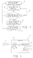
access control system 70 of the present invention including a mechanicalaccess control key 72 which is interfaced with aprinter 74. More particularly,printer 74 includes aprocessor 76 which is connected to aprint engine 78 via aconductor 80.Processor 76 andprint engine 78 are similar in structure and function toprocessor 40 andprint engine 38 described above with reference to Fig. 2.Processor 76 is also connected to a mechanicalkey input device 82 via aconductor 84. Mechanicalkey input device 82 includes arotatable tumbler 86 which is movable between two positions corresponding to an economy mode and a high quality mode of printing. Mechanicalaccess control key 72, which is in the form of a turn key in the embodiment shown, is insertable intoslot 88 oftumbler 86.Tumbler 86 is in a position corresponding to the economy mode as shown in Fig. 4, and can also be rotated clockwise approximately 90 degrees to a position corresponding to the high quality mode ofprinter 74. Mechanicalkey input device 82 is configured to provide an output signal which is transmitted overconductor 84 toprocessor 76. The output signal is indicative of the selected mode of operation ofprinter 74.Processor 76controls print engine 78 viaconductor 80 to effect a desired mode of operation. Mechanicalaccess control key 72 therefore provides selective and discriminate switching ofprint engine 78 from one mode of operation to another mode, such as from an economy mode to a high quality mode. - Fig. 5 illustrates a flowchart for
access control system 70 shown in Fig. 4. First, the user desires access to a feature and/or (sub)system of printer 70 (block 120). The printer system then requests a mechanical access control key prior to allowing the printer feature and/or (sub)system to be accessed (block 122). The mechanical access key in Fig. 4 is in the form of a turn key which is inserted intoslot 88 of mechanicalkey input device 82. A decision is then made as to whether the mechanical access key is valid for access to the desired feature and/or (sub)system (decision block 124). If the result is NO (line 126), control passes back to block 122. On the other hand, if the mechanical access key is valid and the result fromdecision block 124 is YES (line 128), then the user is allowed access to the printer feature and/or (sub)systems (block 130). For example, the user may change the mode of operation ofprinter 70 from an economy mode to a high quality mode, or vice versa. After the user is allowed access to the printer feature and/or (sub)systems, the printer feature and/or (sub)systems are locked out (block 132) and control passes back to block 120. - Fig. 6 schematically illustrates another embodiment of an
access control system 100 of the present invention including a mechanicalaccess control key 102 in the form of a coin.Coin 102 is interfaced with acoin input device 104 of aprinter 106.Coin input device 104 is connected viaconductor 108 to aprocessor 110 which in turn is connected viaconductor 112 toprint engine 114.Coin input device 104 includes appropriate mechanical sensors and circuitry (not shown) to determine a total monetary amount ofcoins 102 inserted intocoin input device 104. The monetary value corresponding to the number ofcoins 102 inserted intocoin input device 104 is used to determine when a feature and/or (sub)system ofprinter 106 may be accessed for use or modification. For example, the monetary value of the number ofcoins 102 inserted intocoin input device 104 can be used to control access to a mode of operation of the printer such as an economy mode or high quality mode, the total number of sheets which may be used, or a time period during which the printer may be used. The monetary value can also be used to allow a user to switch from one mode of operation to another during use, such as from an economy mode to a high quality mode, based on the monetary value remaining at the time a request to change the mode of operation is made. - The logic and method of operation for
printer 100 shown in Fig. 6 is the same as that illustrated by the flowchart in Fig. 5. - In the embodiments shown in Figs. 4 and 6, respectively, the mechanical access control key is in the form of a turn key 72 and
coin 102, respectively. However, it is also to be understood that other mechanical access control keys may also be utilized. Other examples may include a magnetically coded access card, or dip switches on the printer having limited access thereto. - The access control system of the present invention has many possible applications. For example, a parent may wish to limit the amount of consumable supplies which a child is allowed to use. Moreover, a technology administrator for a business may wish to control which persons in the business are allowed to use the printer in a specific mode of operation. Further, it is possible that hotels may place a computer and printer within a room for use by a patron. The printer could be locked out of operation unless a specific access control key is entered by the patron. Other uses are also possible.
- Further, with regard to the embodiment of
access control system 30 shown in Fig. 2,host computer 34 is directly connected toprinter 32 viaconductor 36, such as a parallel or serial cable. However, it is also to be understood thatprinter 32 may be connected to and controlled by a computer which is not directly attached thereto. For example, it may be desirable to controlprinter 32 over a local area network (LAN). It may also be possible to use a tone generating chip such as found in a conventional telephone to access a remotely located system including a tone demodulation circuit for entering a pass code allowing a feature and/or (sub)system of a printer located at the remote station to be accessed (similar to accessing an electronic voice mail system using a touch tone telephone). - While this invention has been described as having a preferred design, the present invention can be further modified within the scope of this disclosure. This application is therefore intended to cover variations, uses, or adaptations of the invention using its general principles. Further, this application is intended to cover such departures from the present disclosure as come within known or customary practice in the art to which this invention pertains and which fall within the limits of the appended claims.
Claims (20)
- An image forming apparatus, comprising:a print engine operable in at least two modes; andan access control system connected to and controlling said print engine, said access control system including an access control key for allowing selective and discriminate switching of said print engine from one of said at least two modes to an other of said at least two modes.
- The image forming apparatus of Claim 1, wherein said at least two modes comprise an economy mode and a high quality mode, said economy mode using less of a consumable supply than said high quality mode.
- The image forming apparatus of Claim 1 or 2, wherein said consumable supply comprises ink.
- The image forming apparatus of Claims 2 and 3, wherein said high quality mode comprises a band interlaced mode.
- The image forming apparatus of Claims 2 and 3, or Claim 4, wherein said economy mode comprises an ink saver mode.
- The image forming apparatus of Claim 1 or 2, wherein said consumable supply comprises toner.
- The image forming apparatus of any preceding Claim, wherein said consumable supply comprises paper.
- The image forming apparatus of any preceding Claim, wherein said consumable supply comprises time.
- The image forming apparatus of any preceding Claim, wherein said access control key comprises an electronic access control key.
- The image forming apparatus of Claim 9, wherein said electronic access control key comprises an electrical signal.
- The image forming apparatus of Claim 9, wherein said electronic access control key comprises a password.
- The image forming apparatus of any of Claims 1 to 8, wherein said access control key comprises a mechanical access control key.
- The image forming apparatus of Claim 12, wherein said mechanical access control key comprises a turn key.
- The image forming apparatus of Claim 12, wherein said mechanical access control key comprises a coin.
- The image forming apparatus of any preceding Claim, wherein the image forming apparatus comprises a printer.
- The image forming apparatus of any preceding Claim, wherein said access control system comprises a processor.
- The image forming apparatus of Claim 16, wherein said access control system further comprises a host computer connected to said processor.
- The image forming apparatus of Claim 16, wherein said access control system further comprises a mechanical key input device connected to said processor.
- A method of forming an image on a print medium, comprising the steps of:providing a print engine operable in at least two modes;providing an access control system connected to and controlling said print engine;providing an access control key;interfacing said access control key with said access control system; andswitching said print engine from one of said at least two modes to an other of said at least two modes using said access control system, dependent on said interfaced access control key.
- The method of Claim 19, wherein said print engine is operable in an economy mode and a high quality mode, and wherein said switching step comprises switching said print engine from one of said economy mode and said high quality mode to the other of said economy mode and said high quality mode.
Applications Claiming Priority (2)
| Application Number | Priority Date | Filing Date | Title |
|---|---|---|---|
| US08/628,177 US6490049B1 (en) | 1996-04-04 | 1996-04-04 | Image forming apparatus with controlled access |
| US628177 | 1996-04-04 |
Publications (2)
| Publication Number | Publication Date |
|---|---|
| EP0799709A1 EP0799709A1 (en) | 1997-10-08 |
| EP0799709B1 true EP0799709B1 (en) | 2000-01-19 |
Family
ID=24517801
Family Applications (1)
| Application Number | Title | Priority Date | Filing Date |
|---|---|---|---|
| EP97302330A Expired - Lifetime EP0799709B1 (en) | 1996-04-04 | 1997-04-04 | Image forming apparatus with controlled access |
Country Status (8)
| Country | Link |
|---|---|
| US (1) | US6490049B1 (en) |
| EP (1) | EP0799709B1 (en) |
| JP (1) | JPH1067160A (en) |
| KR (1) | KR100453395B1 (en) |
| AU (1) | AU716580B2 (en) |
| BR (1) | BR9701674A (en) |
| CA (1) | CA2198977C (en) |
| DE (1) | DE69701161T2 (en) |
Cited By (1)
| Publication number | Priority date | Publication date | Assignee | Title |
|---|---|---|---|---|
| WO2017030571A1 (en) * | 2015-08-18 | 2017-02-23 | Hewlett-Packard Development Company, L.P. | Printer configuration for use of printing material |
Families Citing this family (15)
| Publication number | Priority date | Publication date | Assignee | Title |
|---|---|---|---|---|
| JP4181667B2 (en) * | 1998-09-04 | 2008-11-19 | キヤノン株式会社 | Image processing apparatus, image processing method, and recording medium |
| EP1056014A1 (en) * | 1999-05-28 | 2000-11-29 | Hewlett-Packard Company | System for providing a trustworthy user interface |
| JP4254052B2 (en) * | 2000-01-04 | 2009-04-15 | コニカミノルタビジネステクノロジーズ株式会社 | OUTPUT SYSTEM, OUTPUT METHOD USED FOR THE SAME, AND RECORDING MEDIUM RECORDING PROGRAM EXECUTED IN OUTPUT SYSTEM |
| US20020129259A1 (en) * | 2001-03-06 | 2002-09-12 | Chatterton Scott Johnson | System and method for accessing peripheral devices |
| KR20030018465A (en) * | 2001-08-29 | 2003-03-06 | 삼성전자주식회사 | Printing method of ink saving mode at inkjet printer |
| DE10220484A1 (en) * | 2002-05-07 | 2003-11-27 | Deutsche Post Ag | Method and apparatus for printing token sets |
| US9508046B2 (en) * | 2003-07-22 | 2016-11-29 | Hewlett-Packard Development Company, L.P. | Methods and systems for providing web content to a printing device |
| US20050094182A1 (en) * | 2003-11-03 | 2005-05-05 | Curtis Reese | Printer access control |
| US7520437B2 (en) * | 2005-06-21 | 2009-04-21 | Lexmark International, Inc. | USB host device for printer interface |
| JP4305428B2 (en) * | 2005-08-04 | 2009-07-29 | コニカミノルタビジネステクノロジーズ株式会社 | Device management program and device management apparatus |
| US8842312B2 (en) * | 2007-11-20 | 2014-09-23 | Kyocera Document Solutions Inc. | Application-based profiles of printer driver settings |
| JP5218003B2 (en) * | 2008-12-12 | 2013-06-26 | 株式会社リコー | Image forming apparatus, authentication method, and program |
| KR20120095242A (en) * | 2011-02-18 | 2012-08-28 | 삼성전자주식회사 | Print controling terminal and method for controling print |
| CN102894969B (en) * | 2012-10-23 | 2015-04-29 | 深圳市理邦精密仪器股份有限公司 | Electrocardiogram machine with function of rapidly switching print modes |
| JP2021133520A (en) * | 2020-02-25 | 2021-09-13 | セイコーエプソン株式会社 | Image formation apparatus |
Family Cites Families (12)
| Publication number | Priority date | Publication date | Assignee | Title |
|---|---|---|---|---|
| US4179214A (en) * | 1978-01-09 | 1979-12-18 | Pako Corporation | Photographic printer control system |
| JPS5967063A (en) | 1982-10-08 | 1984-04-16 | Seikosha Co Ltd | Printing method of dot printer |
| US4813912A (en) | 1986-09-02 | 1989-03-21 | Pitney Bowes Inc. | Secured printer for a value printing system |
| US4812841A (en) | 1987-05-26 | 1989-03-14 | Chen Hai C | Computer-controlled password lock |
| JPH02144574A (en) * | 1988-11-25 | 1990-06-04 | Toshiba Corp | Electrophotographic system printer device |
| US4959860A (en) | 1989-02-07 | 1990-09-25 | Compaq Computer Corporation | Power-on password functions for computer system |
| US5075875A (en) * | 1990-04-20 | 1991-12-24 | Acuprint, Inc. | Printer control system |
| US5097506A (en) | 1990-05-18 | 1992-03-17 | Compaq Computer Corporation | Keyboard password lock |
| US5091939A (en) | 1990-06-22 | 1992-02-25 | Tandy Corporation | Method and apparatus for password protection of a computer |
| DE4031110A1 (en) * | 1990-10-02 | 1992-04-09 | Agfa Gevaert Ag | METHOD FOR MONITORING COPYING PROCESSES |
| JP2810813B2 (en) | 1991-10-03 | 1998-10-15 | 富士通株式会社 | Printing control device |
| US5475801A (en) * | 1992-06-12 | 1995-12-12 | Xerox Corporation | System for controlling the printing of electronic documents with various page description languages and other parameters |
-
1996
- 1996-04-04 US US08/628,177 patent/US6490049B1/en not_active Expired - Lifetime
-
1997
- 1997-03-03 CA CA002198977A patent/CA2198977C/en not_active Expired - Fee Related
- 1997-04-03 KR KR1019970012325A patent/KR100453395B1/en not_active IP Right Cessation
- 1997-04-03 AU AU17705/97A patent/AU716580B2/en not_active Ceased
- 1997-04-04 DE DE69701161T patent/DE69701161T2/en not_active Expired - Fee Related
- 1997-04-04 BR BR9701674A patent/BR9701674A/en not_active Application Discontinuation
- 1997-04-04 EP EP97302330A patent/EP0799709B1/en not_active Expired - Lifetime
- 1997-04-04 JP JP9102653A patent/JPH1067160A/en active Pending
Cited By (2)
| Publication number | Priority date | Publication date | Assignee | Title |
|---|---|---|---|---|
| WO2017030571A1 (en) * | 2015-08-18 | 2017-02-23 | Hewlett-Packard Development Company, L.P. | Printer configuration for use of printing material |
| CN107921799A (en) * | 2015-08-18 | 2018-04-17 | 惠普发展公司,有限责任合伙企业 | Configured for the printer that printed material uses |
Also Published As
| Publication number | Publication date |
|---|---|
| CA2198977A1 (en) | 1997-10-04 |
| EP0799709A1 (en) | 1997-10-08 |
| BR9701674A (en) | 1998-09-08 |
| JPH1067160A (en) | 1998-03-10 |
| US6490049B1 (en) | 2002-12-03 |
| AU1770597A (en) | 1997-10-09 |
| DE69701161T2 (en) | 2000-09-28 |
| MX9702497A (en) | 1997-10-31 |
| DE69701161D1 (en) | 2000-02-24 |
| KR100453395B1 (en) | 2005-05-24 |
| KR970071352A (en) | 1997-11-07 |
| CA2198977C (en) | 2003-08-19 |
| AU716580B2 (en) | 2000-03-02 |
Similar Documents
| Publication | Publication Date | Title |
|---|---|---|
| EP0799709B1 (en) | Image forming apparatus with controlled access | |
| US6927865B1 (en) | Information processing apparatus and method utilizing print previews, and computer-readable storage medium | |
| US7092111B2 (en) | Information processing apparatus, print data forming method, print control program, and memory medium | |
| US6724492B1 (en) | Image forming apparatus capable of performing trial printing, and image forming system | |
| CN100595072C (en) | Data processing apparatus and control method therefor | |
| US5528374A (en) | Networked reproduction apparatus with security feature | |
| CA2362229A1 (en) | Interactive printing with a plurality of printer devices | |
| JP5197787B2 (en) | Host computer, control method, and storage medium | |
| EP0926586A2 (en) | Image printing system and partitioned printing method therein | |
| EP0539135B1 (en) | Printing apparatus | |
| KR19990086289A (en) | Apparatus and method for outputting a presentation document | |
| MXPA97002497A (en) | Image format device with control access | |
| JPH08328770A (en) | Printer | |
| KR100777040B1 (en) | Image forming method and image processing apparatus | |
| JP2002361986A (en) | Imaging apparatus | |
| US7269371B2 (en) | Imaging apparatus having interface device for print mode selection | |
| US20240036777A1 (en) | Printing system and methods for conflict checking in printing operations | |
| JP3335062B2 (en) | Print control device and print control method | |
| KR0164837B1 (en) | Printing control method of a complex printer | |
| KR100255193B1 (en) | Method for setting zoom function sphere and unit in printer | |
| JPH08324074A (en) | Network corresponding printer | |
| JPH1079820A (en) | Composite machine | |
| JP4084442B2 (en) | Image forming system | |
| JPH07247048A (en) | Recording device | |
| JP2001341390A (en) | Printing system |
Legal Events
| Date | Code | Title | Description |
|---|---|---|---|
| PUAI | Public reference made under article 153(3) epc to a published international application that has entered the european phase |
Free format text: ORIGINAL CODE: 0009012 |
|
| AK | Designated contracting states |
Kind code of ref document: A1 Designated state(s): DE FR GB IT |
|
| 17P | Request for examination filed |
Effective date: 19971205 |
|
| GRAG | Despatch of communication of intention to grant |
Free format text: ORIGINAL CODE: EPIDOS AGRA |
|
| 17Q | First examination report despatched |
Effective date: 19990401 |
|
| GRAG | Despatch of communication of intention to grant |
Free format text: ORIGINAL CODE: EPIDOS AGRA |
|
| GRAH | Despatch of communication of intention to grant a patent |
Free format text: ORIGINAL CODE: EPIDOS IGRA |
|
| GRAH | Despatch of communication of intention to grant a patent |
Free format text: ORIGINAL CODE: EPIDOS IGRA |
|
| GRAA | (expected) grant |
Free format text: ORIGINAL CODE: 0009210 |
|
| AK | Designated contracting states |
Kind code of ref document: B1 Designated state(s): DE FR GB IT |
|
| REF | Corresponds to: |
Ref document number: 69701161 Country of ref document: DE Date of ref document: 20000224 |
|
| ET | Fr: translation filed | ||
| ITF | It: translation for a ep patent filed |
Owner name: SOCIETA' ITALIANA BREVETTI S.P.A. |
|
| PLBE | No opposition filed within time limit |
Free format text: ORIGINAL CODE: 0009261 |
|
| STAA | Information on the status of an ep patent application or granted ep patent |
Free format text: STATUS: NO OPPOSITION FILED WITHIN TIME LIMIT |
|
| 26N | No opposition filed | ||
| REG | Reference to a national code |
Ref country code: GB Ref legal event code: IF02 |
|
| PGFP | Annual fee paid to national office [announced via postgrant information from national office to epo] |
Ref country code: DE Payment date: 20070531 Year of fee payment: 11 |
|
| PGFP | Annual fee paid to national office [announced via postgrant information from national office to epo] |
Ref country code: GB Payment date: 20070425 Year of fee payment: 11 |
|
| PGFP | Annual fee paid to national office [announced via postgrant information from national office to epo] |
Ref country code: IT Payment date: 20070521 Year of fee payment: 11 |
|
| PGFP | Annual fee paid to national office [announced via postgrant information from national office to epo] |
Ref country code: FR Payment date: 20070417 Year of fee payment: 11 |
|
| GBPC | Gb: european patent ceased through non-payment of renewal fee |
Effective date: 20080404 |
|
| PG25 | Lapsed in a contracting state [announced via postgrant information from national office to epo] |
Ref country code: DE Free format text: LAPSE BECAUSE OF NON-PAYMENT OF DUE FEES Effective date: 20081101 |
|
| REG | Reference to a national code |
Ref country code: FR Ref legal event code: ST Effective date: 20081231 |
|
| PG25 | Lapsed in a contracting state [announced via postgrant information from national office to epo] |
Ref country code: FR Free format text: LAPSE BECAUSE OF NON-PAYMENT OF DUE FEES Effective date: 20080430 |
|
| PG25 | Lapsed in a contracting state [announced via postgrant information from national office to epo] |
Ref country code: GB Free format text: LAPSE BECAUSE OF NON-PAYMENT OF DUE FEES Effective date: 20080404 |
|
| PG25 | Lapsed in a contracting state [announced via postgrant information from national office to epo] |
Ref country code: IT Free format text: LAPSE BECAUSE OF NON-PAYMENT OF DUE FEES Effective date: 20080404 |