EP0799112B1 - Ratchet wrench - Google Patents
Ratchet wrench Download PDFInfo
- Publication number
- EP0799112B1 EP0799112B1 EP95940343A EP95940343A EP0799112B1 EP 0799112 B1 EP0799112 B1 EP 0799112B1 EP 95940343 A EP95940343 A EP 95940343A EP 95940343 A EP95940343 A EP 95940343A EP 0799112 B1 EP0799112 B1 EP 0799112B1
- Authority
- EP
- European Patent Office
- Prior art keywords
- handle
- drive
- axis
- drive member
- ratchet
- Prior art date
- Legal status (The legal status is an assumption and is not a legal conclusion. Google has not performed a legal analysis and makes no representation as to the accuracy of the status listed.)
- Expired - Lifetime
Links
Images


Classifications
-
- B—PERFORMING OPERATIONS; TRANSPORTING
- B25—HAND TOOLS; PORTABLE POWER-DRIVEN TOOLS; MANIPULATORS
- B25B—TOOLS OR BENCH DEVICES NOT OTHERWISE PROVIDED FOR, FOR FASTENING, CONNECTING, DISENGAGING, OR HOLDING
- B25B13/00—Spanners; Wrenches
-
- B—PERFORMING OPERATIONS; TRANSPORTING
- B25—HAND TOOLS; PORTABLE POWER-DRIVEN TOOLS; MANIPULATORS
- B25B—TOOLS OR BENCH DEVICES NOT OTHERWISE PROVIDED FOR, FOR FASTENING, CONNECTING, DISENGAGING, OR HOLDING
- B25B13/00—Spanners; Wrenches
- B25B13/46—Spanners; Wrenches of the ratchet type, for providing a free return stroke of the handle
- B25B13/461—Spanners; Wrenches of the ratchet type, for providing a free return stroke of the handle with concentric driving and driven member
- B25B13/467—Spanners; Wrenches of the ratchet type, for providing a free return stroke of the handle with concentric driving and driven member which are gear-operated
Definitions
- This invention relates to a ratchet wrench of the kind used for driving socket spanners and other similar devices for securing and releasing fasteners, such as for example nuts and bolts, by turning them.
- Conventional ratchet wrenches are well known devices which essentially comprise a mechanism for transposing reciprocating circular arcuate movement of a handle into uni-directional rotation of a drive member for the purposes described above.
- the handle is usually an arm that extends radially outwardly from the axis of the drive member, most usually in a plane perpendicular to the drive member, although the arm can be cranked or jointed.
- the drive member normally has a projection such as a square drive shaft to be received in, for example, a fastener socket.
- devices which have dual means of producing rotation of the drive member. These may, for example, supplement conventional means of operation, using ratchet mechanisms, with rotary members on the handles, which when turned about the longitudinal axis of the handle also produce rotation of the drive member.
- Such devices are particularly useful in confined spaces where conventional use of a wrench is difficult, especially if the torque required to rotate a fastener by hand is quite high, and the confined space means conventional use of the wrench would be very time-consuming.
- Conventional ratchet wrenches may also prove cumbersome when, for example, a nut and bolt assembly is incapable of providing the resistance required to enable the wrench to 'ratchet' or slip.
- United States Patent No 4299145 employs two counter-rotating ring gears positioned concentrically about an output drive member and a bevel gear drive pinion between them turned in either direction by a shaft through the wrench handle. Ratchet mechanisms for each ring gear ensure that the drive member rotates uni-directionally whatever the direction of rotation of the shaft, which is achieved by a spiral mechanism which transposes linear motion of a sleeve into rotary motion of the shaft.
- Both of these devices are capable of use in the conventional fashion, by turning the handle to and fro, whereupon the teeth on opposite sides of the bevel gear pinion act equally on the two ring gears and transmit torque to the drive member via the two ratchet mechanisms working to turn the ring gears, or slip, together.
- United States Patent No 4699028 is an example of a less complex device.
- a conventional ratchet wrench is employed with a ratchet switch capable of decoupling the ratchet mechanism from the output drive member to permit the alternative mode of operation.
- This is also achieved by coupling one end of a rotatable shaft, extending through the wrench handle, to the drive member by a single bevel gear arrangement, and the other end of the shaft is coupled to a "spin knob" projecting from the end of the arm.
- this arrangement there is no ratchet mechanism operating in the coupling between the "spin knob” and the output drive member. Therefore, if the direction of rotation of the "spin knob" is reversed the direction of rotation of the output drive member will also be reversed.
- a shaft in the handle of the wrench is coupled to the output drive member through two driven bevel gears each with an associated ratchet pawl.
- Rotation of the handle about the axis of the output drive member in either direction results in the output drive member rotating in the same direction by the action of the ratchet pawl.
- the shaft in the handle carries a continuous drive bevel gear which meshes with the two driven bevel gears.
- the teeth on the driven bevel gears are not continuous so that the shaft cannot be rotated continuously in one direction to rotate the output drive member.
- To rotate the output drive member the shaft in the handle is oscillated resulting in continuous rotation of the output drive member in one direction by the action of the ratchet pawls.
- United States Patent No 4592256 describes a ratchet wrench in which a single ratchet pawl is used to control the rotation of the output drive member in a selected direction by rotation of the handle.
- the pawl is moved into a neutral position to allow for rotation of the output drive member by rotation of a shaft in the handle. Since the ratchet pawl is disconnected in its neutral position the direction of rotation of the output drive member is dependent on the direction of rotation of the shaft.
- United States Patent No 3952617 offers a further approach in which a rotatable shaft in the wrench handle is permanently connected to the drive member by bevel gearing, and a double ratchet arrangement in the handle between the rotatable shaft and a covering sleeve is controlled by a system of sliding wedges. Again, all the torque is always transmitted through the bevel gears.
- European Patent Application No 0486710 is concerned with a drive transmission for a wrench.
- a motor drive in the wrench handle in order to speed up the action of the wrench.
- This motorised embodiment uses a variant of the transmission which has a particular ratchet and double pawl arrangement that enables the torque from the motor to be supplemented by sufficiently rapid manual forward strokes of the wrench handle. There is no suggestion that this particular ratchet and pawl arangement could be beneficial in a purely manually operated wrench.
- United States Patent No 4545267 describes a wrench, according to the preamble of independent claim 1 herein, in which the primary ratchet drive is achieved by means of a pawl on the drive member cooperating with the splined interior of a housing at one end of the wrench handle.
- a rotatable sleeve on the wrench handle is provided for turning the drive member in the secondary ratchet mode, through the usual bevel gear connection, with the secondary ratchet being located inside the sleeve.
- decoupling devices are used, namely one at each of the two ratchets (their respective neutral positions) together with an arrangement for uncoupling the bevel gear which is needed to avoid the sleeve being turned when the wrench is used in its primary oscillating mode.
- the present invention has for an object to provide a manually operated ratchet wrench with few parts that is capable of being reliable and advantageous in operation.
- such a ratchet wrench may be characterised in that said drive ring is rotatable about said first axis with respect to said output drive member, and said secondary ratchet means is located between the drive ring and the output drive member.
- the ratchet wrench of the invention can consequently couple the output drive member to the drive housing for operation by manually turning the handle to and fro, in conditions of maximum torque and where space allows, reserving operation by the rotary member through the drive ring for lower torques and/or lack of room to swing the handle.
- the rotary member may be located on the handle and turned or spun by finger and thumb action in a confined space or simply for rapid rotation of the drive member in low torque conditions.
- the secondary ratchet action in conjunction with the rotary member is effective even in conditions of low turn resistance in both directions, because the primary ratchet means can be arranged to lock the drive member against reverse rotation and so provide the necessary turn resistance to enable the secondary ratchet to slip.
- the wrench may also comprise selector means adapted to switch either or both of the primary and secondary ratchet means to engage the drive member and turn it either clockwise or counterclockwise upon working the handle or the rotary member as the case may be. Selector means for both ratchet means may be linked whereby both ratchet means are switched together.
- the ratchet wrench has a drive housing from which a fixed arm extends as the handle.
- the drive member in the drive housing has an output drive axis which is perpendicular to the longitudinal axis of the wrench arm.
- the drive ring comprises a bevel ring gear positioned concentrically with the drive housing on the output drive axis.
- the rotary member comprises a sleeve over the arm coupled to a rotatable shaft extending coaxially through the arm, the inner end of which shaft is coupled to the ring gear by another bevel gear.
- the sleeve may be replaced by an alternative such as a knurled wheel or knob.
- the primary ratchet means is normally located between the drive housing and the output drive member.
- the drive housing may have an internally splined cylindrical surface similar to that to be found in conventional ratchet wrenches, and a ratchet pawl may be mounted in the drive member.
- the drive ring may comprise an aperture shaped identically to that of the first drive means, and an outer surface, part of which is shaped as a bevel tooth gear, and part as a plain cylindrical surface.
- the wrench arm In conventional operation the wrench arm is swung in the plane perpendicular to the output drive axis in the normal fashion.
- the drive housing In a first direction the drive housing is coupled to the output drive member by the primary ratchet means engaging with the drive housing, and in the opposite direction the drive housing is decoupled from the output drive member as the ratchet mechanism 'ratchets' on the splined inner surface of the drive housing.
- the drive ring rotates with the output drive member in the driving direction, such that the sleeve on the drive handle remains stationary; whilst in the reverse direction, a force proportional to the resistance of the secondary ratchet mechanism will be imparted to the drive shaft and sleeve on the handle which can easily be resisted to prevent the drive member from rotating.
- the arrangement of the present embodiment is such that the highest forces imparted to the wrench are transmitted through the body, or drive housing, only, in the same manner as conventional wrenches, and not through the bevel gears.
- more complex known devices require such loads to be transmitted through a plurality of complex components including gear teeth.
- more simple devices often require a switching act to change between the different modes of operation, or have no 'ratchetting' provision whatsoever for non-conventional operation. Whilst this may not prove a problem when, for example, a nut and bolt assembly is loose, it may well do so when the resistance offered is greater, especially if that resistance is intermittent.
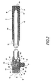
- wrench 10 comprises a handle 11 comprising a knurled sleeve 12 on a fixed arm 14 which extends in a plane perpendicular to the longitudinal axis of a drive housing 15.
- An upper portion 16 of the housing has a splined cylindrical inner surface 17, whilst a lower portion 18 comprises a plain concentric cylindrical inner surface 19, below a concentric frusto-conical shoulder 20.
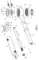
- a bevel drive ring gear 21 comprises a plain cylindrical outer surface 22, and a concentric bore which has a splined cylindrical surface 23 that is in this case dimensionally identical to that of the upper portion of the housing.
- the ring gear is located within the lower housing portion 18 such that it rotates freely and concentrically therein.
- the arm 14 is a cylindrical tube integral with the drive housing in which a rotatable shaft 24 is mounted.
- the inner end of the shaft is adapted to form a bevel pinion gear 25 which fits closely against a tapered inner end to the tubular arm 14 located directly adjacent drive housing 15.
- the position of the taper is such that an aperture 26 is formed on conical shoulder 20 of the housing lower portion 18, as best seen in Fig 4, to allow the pinion bevel gear to mesh with the bevel ring gear 21.
- the taper is located such that it does not intrude into splined cylindrical inner surface 17 of the upper portion of the drive housing.
- the outer end of the shaft 24 extends beyond the arm 14, and is provided with a splined projection 27 coupled to handle sleeve 12, and retained by a screw 29 or other suitable fastener.
- the shaft is retained in position by a sprung circlip 30 which locates in an undercut 31 inside the arm.
- Sleeve 12 serves as a rotary member coupled by the shaft 24 and the bevel pinion gear 25 to the bevel drive ring gear 21.
- An output drive member 13 is positioned for concentric rotation within the drive housing and drive ring, by upper flange 32 which locates in recess 33 above the housing upper portion 16.
- An undercut 34 is provided at the opposite lower end of the drive member for alignment with a recess 35 on the lower face of ring gear 21 such that a sprung fastener 36 retains both components in housing 15.
- a polygonal projection 37 in this case a standard square drive stud, incorporating a spring-loaded ball 38, extends from the drive member for coupling to a conventional drive socket or other device to be turned by the wrench.
- the output drive member 13 also carries the primary and secondary ratchet means. These comprise upper and lower slots 39, 40, which intersect with a cylindrical axial aperture 41, and two pawls 42, 43, which are retained in the slots by pin 44 such that the pawls pivot for simultaneous, but independent engagement with the splined inner surfaces of the upper portion of the housing, in the case of the primary ratchet, and of the drive ring gear, in the case of the secondary ratchet.
- the pivotal position of the pawls is determined by a selector switch 45 in the axial aperture 41 comprising a finger grip 54 on an upper plate 52, a spindle 46, bearing pins 47, 48, and springs 49, 50.
- the switch spindle 46 is positioned for rotation in aperture 41 with upper plate 52 located in a corresponding recess 53 on the drive member.
- the two bearing pins 47, 48 project from the spindle such that they press on the inward facing surfaces of pawls 42, 43.
- the pins are aligned to urge the pawls to pivot simultaneously in the same direction by springs 49, 50, which underlie the pins in holes 55, 56, on the spindle.
- the switching limits of the spindle are effected by the bearing pins touching the sides of slots 39, 40, whereas the top surface of each slot retains the entire selector mechanism in the drive member.
- operation wrench 10 may be used in a conventional or primary mode, a non-conventional or secondary mode, or a combination of these modes as hereinafter described.
- handle 11 In the primary mode of operation handle 11 is swung in either direction about the output drive axis. In one direction the primary ratchet mechanism couples drive housing 15 to drive member 13 via upper pawl 42 and splined inner surface 17, to cause an output rotation of the drive member in the same direction, whilst in the secondary ratchet mechanism lower pawl 43 engages the splined inner surface 23 of the ring gear 21, but neither drives nor slips, since these elements rotate in unison with the wrench so long as rotary sleeve 12 does not turn on the handle 11.
- the primary ratchet mechanism decouples drive member 13 from the housing 15 such that no rotation of the drive member occurs, provided of course that there is sufficient turn resistance from the fastener to which the drive member is connected, whilst the secondary ratchet mechanism including lower pawl 43 decouples the drive ring 21 from drive member 13.
- sleeve 12 In the secondary mode of operation sleeve 12 is twisted in either direction about the longitudinal axis of arm 14. In one direction the secondary ratchet mechanism couples the splined inner surface 23 of the drive ring 21 to drive member 13 via lower pawl 43 to cause an output rotation of the drive member in the same direction, whilst upper pawl 42 of the primary ratchet decouples the drive member from the splined inner surface 17 of the drive housing.
- the secondary ratchet mechanism decouples drive member 13 from ring gear 21, whilst upper pawl 42 couples the splined surface 17 to drive member 13 such that the drive member is prevented from rotating in the 'ratchetting direction' by any residual forces imparted by the drive ring on the slipping pawl 43.
Landscapes
- Engineering & Computer Science (AREA)
- Mechanical Engineering (AREA)
- Details Of Spanners, Wrenches, And Screw Drivers And Accessories (AREA)
- Dowels (AREA)
- Transmission Devices (AREA)
- Dental Tools And Instruments Or Auxiliary Dental Instruments (AREA)
- Devices For Conveying Motion By Means Of Endless Flexible Members (AREA)
- Clamps And Clips (AREA)
Abstract
Description
Claims (10)
- A ratchet wrench for transmitting two modes of reciprocating manual input motion imparted to a handle into one rotary output motion, in which the two modes of reciprocating manual input motion are a primary mode consisting of manually turning said handle to and fro about a first axis, and a secondary mode consisting of manually rotating a rotary member to and fro on said handle about a second axis intersecting said first axis, comprising:whereby said output drive member (13) can be rotated in a selected direction either by manually turning said handle (14) to and fro about said first axis or by manually rotating said rotary member (24) to and fro about said second axis;an output drive member (13) rotatable about said first axis,a drive housing (15) containing said output drive member,said handle (11) on said drive housing for turning said drive housing about said first axis,said rotary member (24) mounted in said handle and rotatable about said second axis,a drive ring (21) extending around said output drive member inside the housing,coupling means (25) coupling rotation of said rotary member about said second axis with rotation of said drive ring about said first axis,primary ratchet means (17,42), located between the drive ring and the output drive member, for selectively uni-directionally coupling said output drive member to said housing, andsecondary ratchet means (23,43) for selectively uni-directionally coupling said output drive member to said rotary member through said drive ring,
characterised in that said drive ring (21) is rotatable about said first axis with respect to said output drive member (13), and said secondary ratchet means (23,43) is located between the drive ring and the output drive member. - A ratchet wrench as claimed in claim 1 further characterised in that said secondary ratchet means comprises a splined internal cylindrical surface (23) on said drive ring (21) and an adjustable pawl (43) cooperating with said splined cylindrical surface (23).
- A ratchet wrench as claimed in claim 2 further characterised in that said primary ratchet means comprises a splined internal cylindrical surface (17) on said drive housing (15) and an adjustable pawl (42) cooperating with said splined cylindrical surface (17), and both the primary pawl (42) and the secondary pawl (43) are carried on said output drive member (13).
- A ratchet wrench as claimed in any of the preceding claims, further characterised in that said primary and secondary ratchet means comprise linked selector means (45) for simultaneously switching both of said primary and secondary ratchet means (42,43) to engage said output drive member so as to rotate said output drive member in a selected one of two directions under the action of either said handle or said rotary member.
- A ratchet wrench as claimed in claim 4 further characterised in that said primary and secondary ratchet means respectively comprise a primary pawl (42) and a secondary pawl (43) mounted on said drive member (13), and the linked selector means comprise a spindle (45) mounted in an axial aperture within the drive member and carrying means (47,48) for urging the said pawls to pivot between two operative positions corresponding to respective rotary positions of the spindle.
- A ratchet wrench as claimed in any one of the preceding claims further characterised in that said handle (11) comprises a cylindrical tubular arm (14), said rotary member comprises a shaft (24) extending down said tubular arm, said shaft extends towards said splined internal cylindrical surface (23) on said drive ring, and said coupling means is provided at an inner end of said shaft.
- A ratchet wrench as claimed in any one of the preceding claims further characterised in that said drive ring (21) comprises a bevel gear positioned concentrically within said drive housing (15), said handle (11) comprises a cylindrical tubular arm (14), said rotary member comprises a shaft (24) extending down said tubular arm, and said coupling means comprises a bevel pinion (25) on said shaft (24) inside an end thereof and permanently engaged with said bevel gear through an aperture (26) in said end.
- A ratchet wrench as claimed in any one of the preceding claims further characterised in that said coupling means (25) permanently couples said rotary member (24) to said drive ring (21), and said output drive member (13) is always rotatable in the selected direction both by manually turning said handle (14) about said first axis and by manually rotating said rotary member (24) about said second axis.
- A ratchet wrench as claimed in any one of the preceding claims further characterised in that said rotary member (24) on said handle (14) comprises a manually rotatable sleeve (12) extending outside a cylindrical fixed arm portion of said handle.
- A ratchet wrench, according to claim 1, characterised in that said handle (11) comprising a cylindrical tubular arm (14) fixed on said drive housing for manually turning said drive housing about said first axis, and said rotary member comprising a sleeve (12) mounted on said handle outside said fixed arm portion thereof and manually rotatable about said second axis; wherein said drive ring (21) comprises a bevel gear positioned concentrically within said drive housing (15) and rotatable about said first axis with respect to said output drive member (13), said sleeve (12) is mounted on a shaft (24) extending down said tubular arm, and said coupling means comprises a bevel pinion (25) on said shaft (24) inside an end thereof and permanently engaged with said bevel gear through an aperture (26) in said end.
Applications Claiming Priority (3)
| Application Number | Priority Date | Filing Date | Title |
|---|---|---|---|
| GBGB9426247.4A GB9426247D0 (en) | 1994-12-24 | 1994-12-24 | Ratchet wrench |
| GB9426247 | 1994-12-24 | ||
| PCT/GB1995/002879 WO1996020071A1 (en) | 1994-12-24 | 1995-12-11 | Ratchet wrench |
Publications (4)
| Publication Number | Publication Date |
|---|---|
| EP0799112A1 EP0799112A1 (en) | 1997-10-08 |
| EP0799112B1 true EP0799112B1 (en) | 2004-09-15 |
| EP0799112B9 EP0799112B9 (en) | 2006-06-28 |
| EP0799112B3 EP0799112B3 (en) | 2010-07-14 |
Family
ID=10766610
Family Applications (1)
| Application Number | Title | Priority Date | Filing Date |
|---|---|---|---|
| EP95940343A Expired - Lifetime EP0799112B3 (en) | 1994-12-24 | 1995-12-11 | Ratchet wrench |
Country Status (12)
| Country | Link |
|---|---|
| US (1) | US6070499A (en) |
| EP (1) | EP0799112B3 (en) |
| JP (1) | JP3726842B2 (en) |
| KR (1) | KR100376396B1 (en) |
| CN (1) | CN1046883C (en) |
| AT (1) | ATE276073T1 (en) |
| AU (1) | AU707117B2 (en) |
| CA (1) | CA2208163C (en) |
| DE (1) | DE69533521C5 (en) |
| ES (1) | ES2229244T7 (en) |
| GB (1) | GB9426247D0 (en) |
| WO (1) | WO1996020071A1 (en) |
Cited By (2)
| Publication number | Priority date | Publication date | Assignee | Title |
|---|---|---|---|---|
| TWI571360B (en) * | 2014-09-11 | 2017-02-21 | Hou-Fei Hu | Electric sleeve ratchet wrench |
| TWI571361B (en) * | 2014-09-16 | 2017-02-21 | Hou-Fei Hu | Electric sleeve ratchet wrench |
Families Citing this family (51)
| Publication number | Priority date | Publication date | Assignee | Title |
|---|---|---|---|---|
| DE20010055U1 (en) * | 2000-06-05 | 2000-08-31 | Chu, Te Chen, Da Li, Taichung | Ratchet wrench |
| DE20116477U1 (en) * | 2001-10-08 | 2001-12-13 | Huang, Chin-Chen, Taichung | Torque transmission mechanism for socket wrenches |
| US6457386B1 (en) * | 2002-01-11 | 2002-10-01 | Shui-Lai Chiang | Ratchet wrench |
| US6684738B2 (en) * | 2002-02-19 | 2004-02-03 | Chin-Chen Huang | Handle for socket wrench |
| US20040129114A1 (en) * | 2003-01-02 | 2004-07-08 | Terence Chen | Versatile wrench |
| US6923095B2 (en) | 2003-09-19 | 2005-08-02 | Mechanics Custom Tools Corporation | Tensionless power ratchet wrench assembly |
| CN1309531C (en) * | 2003-10-09 | 2007-04-11 | 陈泰佐 | reversing drive rotary wrench |
| US7104165B2 (en) * | 2004-01-16 | 2006-09-12 | Te-Chen Chu | Swing head structure of wrench with two kinds of torque output |
| US20060060032A1 (en) * | 2004-09-21 | 2006-03-23 | David Baker | Reset gear, method of use, and ratchet wrench utilizing said gear |
| US7004052B1 (en) * | 2004-08-11 | 2006-02-28 | A.A.G. Industrial Co. Ltd. | Ratchet wrench with rotating disc |
| US7181996B1 (en) | 2005-12-08 | 2007-02-27 | Te Chen Chu | Ratchet wrench having two driving devices |
| KR100741940B1 (en) | 2006-05-12 | 2007-07-27 | 송관태 | Socket wrench |
| US7444905B2 (en) * | 2006-10-26 | 2008-11-04 | Bobby Hu | Wrench with reinforced hollow handle |
| US7267033B1 (en) * | 2006-12-19 | 2007-09-11 | Chun Chou Lai | Ratchet wrench having two driving torques |
| US7895923B2 (en) | 2007-02-16 | 2011-03-01 | Bobby Hu | Wrench with reinforced hollow handle |
| TWI490090B (en) * | 2009-07-31 | 2015-07-01 | Stanley D Winnard | Ratcheting joint capable of rotation, folding ratcheting pry bar, and foldable enclosure |
| DE202009005130U1 (en) | 2009-08-12 | 2009-12-31 | Pard Hardware Industrial Co., Ltd. | Ratchet with two torques |
| EP2295202B1 (en) | 2009-09-15 | 2012-05-23 | Pard Hardware Industrial Co., Ltd. | Wrench for providing two operative modes |
| TWM376132U (en) * | 2009-11-06 | 2010-03-21 | Natura Innovation Ltd | High lopper |
| MX2010002057A (en) | 2010-02-22 | 2011-08-31 | Luis Gerardo Oyervides Ochoa | Wrench comprising self-adjustable rollers. |
| US7966912B1 (en) * | 2010-03-30 | 2011-06-28 | Black & Decker Inc. | Ratcheting wrench |
| EP2601016A2 (en) | 2010-08-06 | 2013-06-12 | American Grease Stick Company | Wrench with trigger |
| CN102601755B (en) * | 2011-01-18 | 2015-06-10 | 宁波工程学院 | Holding type efficient wrench |
| US20120227548A1 (en) * | 2011-03-12 | 2012-09-13 | Lin Da-Sen | One-Way Wrench |
| US9815179B2 (en) | 2012-09-26 | 2017-11-14 | Apex Brands, Inc. | Reversible ratcheting tool with dual pawls |
| MX360127B (en) * | 2013-01-18 | 2018-10-23 | Hangzhou Great Star Tools Co Ltd | Bidirectional wrench. |
| US9643298B2 (en) | 2013-01-18 | 2017-05-09 | Hangzhou Great Star Tools Co., Ltd | Thin bi-directional ratchet wrench |
| US9038505B2 (en) * | 2013-07-28 | 2015-05-26 | Ya-Lan He | Wrench |
| CN103707233B (en) * | 2014-01-24 | 2016-01-13 | 上海美瑞实业有限公司 | The ratchet screwdriver of two-way work doing |
| US9114511B1 (en) * | 2014-02-24 | 2015-08-25 | Lichten Tools Corporation | Ratchet connector |
| US20150267480A1 (en) * | 2014-03-20 | 2015-09-24 | Seaboard International, Inc. | Ratchet assembly |
| US9457457B2 (en) * | 2014-05-05 | 2016-10-04 | William Tools Co., Ltd. | Ratchet wrench |
| CN105328611A (en) * | 2014-06-19 | 2016-02-17 | 杭州巨星工具有限公司 | Thin bidirectional ratchet wrench |
| CN105458988B (en) * | 2014-09-11 | 2018-06-29 | 胡厚飞 | Electric sleeve barrel ratchet spanner |
| WO2016100734A1 (en) * | 2014-12-18 | 2016-06-23 | Eca Medical Instruments | Disposable bidirectional ratchet |
| US9868190B2 (en) * | 2015-04-21 | 2018-01-16 | Zhe Jiang Yiyang Tool Manufacture Co., Ltd. | Ratchet wrench |
| TWI583503B (en) | 2015-05-22 | 2017-05-21 | Hou-Fei Hu | Electric ratchet wrench |
| TWI604926B (en) | 2015-05-22 | 2017-11-11 | Hou-Fei Hu | Electric ratchet wrench |
| CN106272208B (en) * | 2015-05-22 | 2018-04-24 | 胡厚飞 | Electric ratchet wrench |
| TWI565563B (en) * | 2015-06-03 | 2017-01-11 | 英發企業股份有限公司 | Ratchet tool with a laminated pawl reversing mechanism |
| TWI587985B (en) * | 2015-09-01 | 2017-06-21 | Hou-Fei Hu | Electric wrench |
| TWI583507B (en) * | 2015-11-02 | 2017-05-21 | Hou-Fei Hu | Fastening wrench of the shaft fixed device and the application of the axis of the fastening device wrench |
| DE102016102100B4 (en) | 2016-02-05 | 2017-11-02 | Chih-Ying Huang | BETWEEN TWO MODES SWITCHING ONE SCREW KEY |
| JP6461274B2 (en) * | 2017-10-05 | 2019-01-30 | 杭州巨星工具有限公司 | Bidirectional wrench |
| CN109356472A (en) * | 2018-12-10 | 2019-02-19 | 贵州航锐航空精密零部件制造有限公司 | A special vehicle unlocking handle |
| TWI722884B (en) * | 2020-04-29 | 2021-03-21 | 華偉工具有限公司 | Ratchet seat, ratchet tool head and two-way ratchet hand tool |
| US12502760B2 (en) | 2021-02-25 | 2025-12-23 | Black & Decker Inc. | Compact powered wrench |
| USD1012643S1 (en) * | 2021-12-21 | 2024-01-30 | Matco Tools Corporation | Ratchet pawl |
| US12251795B2 (en) * | 2022-10-18 | 2025-03-18 | Gong Fong Enterprise Co., Ltd. | Ratchet wrench |
| USD1082467S1 (en) * | 2023-12-22 | 2025-07-08 | Mbull Holdings, Llc | Wrench |
| USD1082466S1 (en) * | 2023-12-22 | 2025-07-08 | Mbull Holdings, Llc | Wrench |
Citations (1)
| Publication number | Priority date | Publication date | Assignee | Title |
|---|---|---|---|---|
| EP0486710A1 (en) * | 1986-11-24 | 1992-05-27 | WILLIAMS III, Thomas A. | Reversible unidirectional transmission |
Family Cites Families (8)
| Publication number | Priority date | Publication date | Assignee | Title |
|---|---|---|---|---|
| US2206802A (en) | 1939-01-23 | 1940-07-02 | Brenning Reuben | Wrench |
| US3952617A (en) | 1973-10-26 | 1976-04-27 | Ray & Spielman | Wrench |
| DE2910821C2 (en) | 1979-03-20 | 1980-11-13 | Rautio, Aaro Juhani, Seinaejoki | Ratchet wrench |
| US4545267A (en) * | 1984-03-05 | 1985-10-08 | Shumway Warren R | Combination gear ratchet wrench apparatus |
| EP0195002A1 (en) | 1984-09-17 | 1986-09-24 | BOSQUE, Raul A. | An improved spinner ratchet wrench |
| US4592256A (en) | 1985-01-22 | 1986-06-03 | Bosque Raul A | Combination ratchet and spinner wrench |
| US5201255A (en) * | 1987-02-02 | 1993-04-13 | Gegg Michael J | Ratchet wrench |
| US5058463A (en) | 1990-10-29 | 1991-10-22 | Midland Design Inc. | Ratchet wrench with dual-rotating constant drive handle |
-
1994
- 1994-12-24 GB GBGB9426247.4A patent/GB9426247D0/en active Pending
-
1995
- 1995-12-11 WO PCT/GB1995/002879 patent/WO1996020071A1/en not_active Ceased
- 1995-12-11 AU AU41821/96A patent/AU707117B2/en not_active Expired
- 1995-12-11 US US08/875,148 patent/US6070499A/en not_active Expired - Lifetime
- 1995-12-11 EP EP95940343A patent/EP0799112B3/en not_active Expired - Lifetime
- 1995-12-11 JP JP52027396A patent/JP3726842B2/en not_active Expired - Fee Related
- 1995-12-11 DE DE69533521T patent/DE69533521C5/en not_active Expired - Lifetime
- 1995-12-11 ES ES95940343T patent/ES2229244T7/en active Active
- 1995-12-11 CA CA002208163A patent/CA2208163C/en not_active Expired - Lifetime
- 1995-12-11 AT AT95940343T patent/ATE276073T1/en not_active IP Right Cessation
- 1995-12-11 CN CN95197035A patent/CN1046883C/en not_active Expired - Lifetime
- 1995-12-11 KR KR1019970704306A patent/KR100376396B1/en not_active Expired - Fee Related
Patent Citations (1)
| Publication number | Priority date | Publication date | Assignee | Title |
|---|---|---|---|---|
| EP0486710A1 (en) * | 1986-11-24 | 1992-05-27 | WILLIAMS III, Thomas A. | Reversible unidirectional transmission |
Cited By (3)
| Publication number | Priority date | Publication date | Assignee | Title |
|---|---|---|---|---|
| TWI571360B (en) * | 2014-09-11 | 2017-02-21 | Hou-Fei Hu | Electric sleeve ratchet wrench |
| US10549410B2 (en) | 2014-09-11 | 2020-02-04 | Bobby Hu | Electric ratchet wrench |
| TWI571361B (en) * | 2014-09-16 | 2017-02-21 | Hou-Fei Hu | Electric sleeve ratchet wrench |
Also Published As
| Publication number | Publication date |
|---|---|
| CN1171073A (en) | 1998-01-21 |
| GB9426247D0 (en) | 1995-02-22 |
| CA2208163A1 (en) | 1996-07-04 |
| EP0799112B9 (en) | 2006-06-28 |
| JP3726842B2 (en) | 2005-12-14 |
| DE69533521D1 (en) | 2004-10-21 |
| ES2229244T7 (en) | 2011-08-01 |
| DE69533521C5 (en) | 2010-10-21 |
| ATE276073T1 (en) | 2004-10-15 |
| CN1046883C (en) | 1999-12-01 |
| CA2208163C (en) | 2008-03-25 |
| AU4182196A (en) | 1996-07-19 |
| WO1996020071A1 (en) | 1996-07-04 |
| KR980700900A (en) | 1998-04-30 |
| JPH11502156A (en) | 1999-02-23 |
| KR100376396B1 (en) | 2003-05-27 |
| AU707117B2 (en) | 1999-07-01 |
| US6070499A (en) | 2000-06-06 |
| ES2229244T3 (en) | 2005-04-16 |
| EP0799112B3 (en) | 2010-07-14 |
| DE69533521T2 (en) | 2005-08-18 |
| EP0799112A1 (en) | 1997-10-08 |
Similar Documents
| Publication | Publication Date | Title |
|---|---|---|
| EP0799112B1 (en) | Ratchet wrench | |
| US5230262A (en) | Ratchet wrench | |
| US7600451B2 (en) | Detachable surgical ratchet | |
| US7942253B2 (en) | Thumb-actuated handle device | |
| US20040040419A1 (en) | Ratchet tool | |
| US7712546B2 (en) | Power tool having torque limiter | |
| US20180206853A1 (en) | Space-saving ratchet unit with freewheel | |
| US6681660B2 (en) | Variable speed ratchet wrench and method of use | |
| CA2768248A1 (en) | Power tool | |
| US4545267A (en) | Combination gear ratchet wrench apparatus | |
| TWI724902B (en) | Ratchet wrench with electric assistance | |
| US5562015A (en) | Automatic ratchet reversal device | |
| US8707831B2 (en) | Dual-drive, self-ratcheting mechanism | |
| US3945274A (en) | Speed wrench | |
| CA1127432A (en) | Rotary impact tool for applying a torque force | |
| US4366731A (en) | Socket wrench | |
| US4592256A (en) | Combination ratchet and spinner wrench | |
| EP3829818B1 (en) | Ratcheting tool | |
| US5180175A (en) | Drill chuck key | |
| US3332304A (en) | Reversible socket wrench handle | |
| US20150047472A1 (en) | Dual-drive, self-ratcheting, mechanism with multiple input ports | |
| KR100604151B1 (en) | Self-rotating socket wrench | |
| AU2001291518B2 (en) | Ratchet tool | |
| JPH10286780A (en) | Ratchet wrench |
Legal Events
| Date | Code | Title | Description |
|---|---|---|---|
| PUAI | Public reference made under article 153(3) epc to a published international application that has entered the european phase |
Free format text: ORIGINAL CODE: 0009012 |
|
| 17P | Request for examination filed |
Effective date: 19970717 |
|
| AK | Designated contracting states |
Kind code of ref document: A1 Designated state(s): AT BE CH DE DK ES FR GB GR IE IT LI LU MC NL PT SE |
|
| GRAG | Despatch of communication of intention to grant |
Free format text: ORIGINAL CODE: EPIDOS AGRA |
|
| 17Q | First examination report despatched |
Effective date: 19980729 |
|
| GRAG | Despatch of communication of intention to grant |
Free format text: ORIGINAL CODE: EPIDOS AGRA |
|
| GRAP | Despatch of communication of intention to grant a patent |
Free format text: ORIGINAL CODE: EPIDOSNIGR1 |
|
| GRAU | Approval following communication of intention to grant |
Free format text: ORIGINAL CODE: EPIDOSNAGR4 |
|
| GRAJ | Information related to disapproval of communication of intention to grant by the applicant or resumption of examination proceedings by the epo deleted |
Free format text: ORIGINAL CODE: EPIDOSDIGR1 |
|
| GRAN | Information related to approval following communication of intention to grant deleted |
Free format text: ORIGINAL CODE: EPIDOSDAGR4 |
|
| GRAP | Despatch of communication of intention to grant a patent |
Free format text: ORIGINAL CODE: EPIDOSNIGR1 |
|
| GRAU | Approval following communication of intention to grant |
Free format text: ORIGINAL CODE: EPIDOSNAGR4 |
|
| GRAS | Grant fee paid |
Free format text: ORIGINAL CODE: EPIDOSNIGR3 |
|
| GRAA | (expected) grant |
Free format text: ORIGINAL CODE: 0009210 |
|
| AK | Designated contracting states |
Kind code of ref document: B1 Designated state(s): AT BE CH DE DK ES FR GB GR IE IT LI LU MC NL PT SE |
|
| PG25 | Lapsed in a contracting state [announced via postgrant information from national office to epo] |
Ref country code: NL Free format text: LAPSE BECAUSE OF FAILURE TO SUBMIT A TRANSLATION OF THE DESCRIPTION OR TO PAY THE FEE WITHIN THE PRESCRIBED TIME-LIMIT Effective date: 20040915 Ref country code: LI Free format text: LAPSE BECAUSE OF FAILURE TO SUBMIT A TRANSLATION OF THE DESCRIPTION OR TO PAY THE FEE WITHIN THE PRESCRIBED TIME-LIMIT Effective date: 20040915 Ref country code: CH Free format text: LAPSE BECAUSE OF FAILURE TO SUBMIT A TRANSLATION OF THE DESCRIPTION OR TO PAY THE FEE WITHIN THE PRESCRIBED TIME-LIMIT Effective date: 20040915 Ref country code: BE Free format text: LAPSE BECAUSE OF FAILURE TO SUBMIT A TRANSLATION OF THE DESCRIPTION OR TO PAY THE FEE WITHIN THE PRESCRIBED TIME-LIMIT Effective date: 20040915 Ref country code: AT Free format text: LAPSE BECAUSE OF FAILURE TO SUBMIT A TRANSLATION OF THE DESCRIPTION OR TO PAY THE FEE WITHIN THE PRESCRIBED TIME-LIMIT Effective date: 20040915 |
|
| REG | Reference to a national code |
Ref country code: GB Ref legal event code: FG4D Ref country code: CH Ref legal event code: EP |
|
| REG | Reference to a national code |
Ref country code: IE Ref legal event code: FG4D |
|
| REF | Corresponds to: |
Ref document number: 69533521 Country of ref document: DE Date of ref document: 20041021 Kind code of ref document: P |
|
| PG25 | Lapsed in a contracting state [announced via postgrant information from national office to epo] |
Ref country code: LU Free format text: LAPSE BECAUSE OF NON-PAYMENT OF DUE FEES Effective date: 20041211 |
|
| PG25 | Lapsed in a contracting state [announced via postgrant information from national office to epo] |
Ref country code: IE Free format text: LAPSE BECAUSE OF NON-PAYMENT OF DUE FEES Effective date: 20041213 |
|
| PG25 | Lapsed in a contracting state [announced via postgrant information from national office to epo] |
Ref country code: SE Free format text: LAPSE BECAUSE OF FAILURE TO SUBMIT A TRANSLATION OF THE DESCRIPTION OR TO PAY THE FEE WITHIN THE PRESCRIBED TIME-LIMIT Effective date: 20041215 Ref country code: GR Free format text: LAPSE BECAUSE OF FAILURE TO SUBMIT A TRANSLATION OF THE DESCRIPTION OR TO PAY THE FEE WITHIN THE PRESCRIBED TIME-LIMIT Effective date: 20041215 Ref country code: DK Free format text: LAPSE BECAUSE OF FAILURE TO SUBMIT A TRANSLATION OF THE DESCRIPTION OR TO PAY THE FEE WITHIN THE PRESCRIBED TIME-LIMIT Effective date: 20041215 |
|
| PG25 | Lapsed in a contracting state [announced via postgrant information from national office to epo] |
Ref country code: MC Free format text: LAPSE BECAUSE OF NON-PAYMENT OF DUE FEES Effective date: 20041231 |
|
| REG | Reference to a national code |
Ref country code: CH Ref legal event code: PL |
|
| NLV1 | Nl: lapsed or annulled due to failure to fulfill the requirements of art. 29p and 29m of the patents act | ||
| REG | Reference to a national code |
Ref country code: ES Ref legal event code: FG2A Ref document number: 2229244 Country of ref document: ES Kind code of ref document: T3 |
|
| PLBE | No opposition filed within time limit |
Free format text: ORIGINAL CODE: 0009261 |
|
| ET | Fr: translation filed | ||
| 26N | No opposition filed |
Effective date: 20050616 |
|
| REG | Reference to a national code |
Ref country code: IE Ref legal event code: MM4A |
|
| PG25 | Lapsed in a contracting state [announced via postgrant information from national office to epo] |
Ref country code: PT Free format text: LAPSE BECAUSE OF NON-PAYMENT OF DUE FEES Effective date: 20050215 |
|
| REG | Reference to a national code |
Ref country code: GB Ref legal event code: 732E |
|
| REG | Reference to a national code |
Ref country code: FR Ref legal event code: TP |
|
| REG | Reference to a national code |
Ref country code: GB Ref legal event code: 732E Free format text: REGISTERED BETWEEN 20090319 AND 20090325 |
|
| REG | Reference to a national code |
Ref country code: FR Ref legal event code: TP |
|
| PLCP | Request for limitation filed |
Free format text: ORIGINAL CODE: EPIDOSNLIM1 |
|
| PLCQ | Request for limitation of patent found admissible |
Free format text: ORIGINAL CODE: 0009231 |
|
| PLCR | Communication despatched that request for limitation of patent was allowed |
Free format text: ORIGINAL CODE: 0009245 |
|
| LIM1 | Request for limitation found admissible |
Free format text: SEQUENCE NO: 1; FILED AFTER OPPOSITION PERIOD Filing date: 20100113 |
|
| PLCN | Payment of fee for limitation of patent |
Free format text: ORIGINAL CODE: EPIDOSNRAL3 |
|
| PUAM | (expected) publication of b3 document |
Free format text: ORIGINAL CODE: 0009410 |
|
| STAA | Information on the status of an ep patent application or granted ep patent |
Free format text: STATUS: THE PATENT HAS BEEN LIMITED |
|
| REG | Reference to a national code |
Ref country code: ES Ref legal event code: PC2A |
|
| REG | Reference to a national code |
Ref country code: CH Ref legal event code: AEN Free format text: BESCHRAENKUNGANTRAG GUTGEHEISSEN |
|
| REG | Reference to a national code |
Ref country code: DE Ref legal event code: R097 Ref document number: 69533521 Country of ref document: DE |
|
| REG | Reference to a national code |
Ref country code: DE Ref legal event code: R040 Ref document number: 69533521 Country of ref document: DE Effective date: 20120511 |
|
| PGFP | Annual fee paid to national office [announced via postgrant information from national office to epo] |
Ref country code: GB Payment date: 20141211 Year of fee payment: 20 |
|
| PGFP | Annual fee paid to national office [announced via postgrant information from national office to epo] |
Ref country code: IT Payment date: 20141210 Year of fee payment: 20 |
|
| PGFP | Annual fee paid to national office [announced via postgrant information from national office to epo] |
Ref country code: DE Payment date: 20141229 Year of fee payment: 20 Ref country code: ES Payment date: 20150116 Year of fee payment: 20 |
|
| PGFP | Annual fee paid to national office [announced via postgrant information from national office to epo] |
Ref country code: FR Payment date: 20141222 Year of fee payment: 20 |
|
| REG | Reference to a national code |
Ref country code: DE Ref legal event code: R071 Ref document number: 69533521 Country of ref document: DE |
|
| REG | Reference to a national code |
Ref country code: GB Ref legal event code: PE20 Expiry date: 20151210 |
|
| PG25 | Lapsed in a contracting state [announced via postgrant information from national office to epo] |
Ref country code: GB Free format text: LAPSE BECAUSE OF EXPIRATION OF PROTECTION Effective date: 20151210 |
|
| REG | Reference to a national code |
Ref country code: ES Ref legal event code: FD2A Effective date: 20160329 |
|
| PG25 | Lapsed in a contracting state [announced via postgrant information from national office to epo] |
Ref country code: ES Free format text: LAPSE BECAUSE OF EXPIRATION OF PROTECTION Effective date: 20151212 |