EP0798558A2 - Plunger pump for a high performance liquid chromatograph - Google Patents
Plunger pump for a high performance liquid chromatograph Download PDFInfo
- Publication number
- EP0798558A2 EP0798558A2 EP97105308A EP97105308A EP0798558A2 EP 0798558 A2 EP0798558 A2 EP 0798558A2 EP 97105308 A EP97105308 A EP 97105308A EP 97105308 A EP97105308 A EP 97105308A EP 0798558 A2 EP0798558 A2 EP 0798558A2
- Authority
- EP
- European Patent Office
- Prior art keywords
- plunger
- plunger pump
- reference position
- dead center
- pulse motor
- Prior art date
- Legal status (The legal status is an assumption and is not a legal conclusion. Google has not performed a legal analysis and makes no representation as to the accuracy of the status listed.)
- Withdrawn
Links
Images

Classifications
-
- G—PHYSICS
- G01—MEASURING; TESTING
- G01N—INVESTIGATING OR ANALYSING MATERIALS BY DETERMINING THEIR CHEMICAL OR PHYSICAL PROPERTIES
- G01N30/00—Investigating or analysing materials by separation into components using adsorption, absorption or similar phenomena or using ion-exchange, e.g. chromatography or field flow fractionation
- G01N30/02—Column chromatography
- G01N30/26—Conditioning of the fluid carrier; Flow patterns
- G01N30/28—Control of physical parameters of the fluid carrier
- G01N30/32—Control of physical parameters of the fluid carrier of pressure or speed
-
- F—MECHANICAL ENGINEERING; LIGHTING; HEATING; WEAPONS; BLASTING
- F04—POSITIVE - DISPLACEMENT MACHINES FOR LIQUIDS; PUMPS FOR LIQUIDS OR ELASTIC FLUIDS
- F04B—POSITIVE-DISPLACEMENT MACHINES FOR LIQUIDS; PUMPS
- F04B49/00—Control, e.g. of pump delivery, or pump pressure of, or safety measures for, machines, pumps, or pumping installations, not otherwise provided for, or of interest apart from, groups F04B1/00 - F04B47/00
- F04B49/06—Control using electricity
- F04B49/065—Control using electricity and making use of computers
-
- F—MECHANICAL ENGINEERING; LIGHTING; HEATING; WEAPONS; BLASTING
- F04—POSITIVE - DISPLACEMENT MACHINES FOR LIQUIDS; PUMPS FOR LIQUIDS OR ELASTIC FLUIDS
- F04B—POSITIVE-DISPLACEMENT MACHINES FOR LIQUIDS; PUMPS
- F04B51/00—Testing machines, pumps, or pumping installations
-
- F—MECHANICAL ENGINEERING; LIGHTING; HEATING; WEAPONS; BLASTING
- F04—POSITIVE - DISPLACEMENT MACHINES FOR LIQUIDS; PUMPS FOR LIQUIDS OR ELASTIC FLUIDS
- F04B—POSITIVE-DISPLACEMENT MACHINES FOR LIQUIDS; PUMPS
- F04B2201/00—Pump parameters
- F04B2201/02—Piston parameters
- F04B2201/0201—Position of the piston
-
- F—MECHANICAL ENGINEERING; LIGHTING; HEATING; WEAPONS; BLASTING
- F04—POSITIVE - DISPLACEMENT MACHINES FOR LIQUIDS; PUMPS FOR LIQUIDS OR ELASTIC FLUIDS
- F04B—POSITIVE-DISPLACEMENT MACHINES FOR LIQUIDS; PUMPS
- F04B2203/00—Motor parameters
- F04B2203/02—Motor parameters of rotating electric motors
- F04B2203/0213—Pulses per unit of time (pulse motor)
-
- G—PHYSICS
- G01—MEASURING; TESTING
- G01N—INVESTIGATING OR ANALYSING MATERIALS BY DETERMINING THEIR CHEMICAL OR PHYSICAL PROPERTIES
- G01N30/00—Investigating or analysing materials by separation into components using adsorption, absorption or similar phenomena or using ion-exchange, e.g. chromatography or field flow fractionation
- G01N30/02—Column chromatography
- G01N30/26—Conditioning of the fluid carrier; Flow patterns
- G01N30/28—Control of physical parameters of the fluid carrier
- G01N30/32—Control of physical parameters of the fluid carrier of pressure or speed
- G01N2030/326—Control of physical parameters of the fluid carrier of pressure or speed pumps
Definitions
- the present invention relates to a plunger pump for a high performance liquid chromatograph (HPLC).
- HPLC high performance liquid chromatograph
- a plunger pump is used in HPLCs because the plunger pump is better at controlling a flow more precisely.
- two or more plunger pumps are used in combination to cancel pulsations in the output of each plunger pump.
- a damper is provided after a plunger pump to absorb pulsations.
- the profile of the cam of the plunger pump is designed so that the suction cycle is set shorter while the discharge cycle is set longer in order to minimize the pulsations in the discharged solvent.
- the cam 10 of a plunger pump is fixed on the shaft 14 of a pulse motor 12, and a photo-interrupter 16 is also fixed on the motor shaft 14.
- a notch 17 is formed in a periphery of the photo-interrupter 16, and an arrangement of a photo-emitter 18 and a photo-receiver 20 are fixed beside the photo-interrupter 16 so that the notch 17 comes between them.
- the photo-emitter 18, photo-receiver 20 and the photo-interrupter 16 constitute a photo-sensor which sends a rotation signal to a controller 22 once in a rotation of the photo-interrupter 16, or once in a rotation of the cam 10.
- the controller 22 Based on the signal from the photosensor, the controller 22 knows the position of the pulse motor 12 and the plunger, and gives a motor control signal to a motor driver 24. Responsive to the motor control signal, the motor driver 24 drives the pulse motor 12 according to the position and speed indicated by the motor control signal.
- the controller 22 determines a reference angular position of the pulse motor 12 (where the plunger is at a dead center) by the position at the time when a preset number of pulses come since the signal from the photosensor came.
- the number of the pulses for determining the reference angular position must be predetermined beforehand in the final adjusting stage of manufacturing. Such an adjusting operation for determining the number of pulses is also necessary in performing maintenance of the plunger pump when the cam is replaced with a new one. Such an adjustment requires a considerable amount of labor and time so that efficiency of the manufacturing and the maintenance of the plunger pump is greatly reduced.
- An object of the present invention is, therefore, to provide a plunger pump suitably used for an HPLC which can detect a dead center precisely without laborious or time-consuming adjusting operations.
- a plunger pump according to the present invention includes:
- the position sensor While, in the adjusting operation, the plunger of the plunger pump is moved by the pulse motor, the position sensor sends a series of position signals to the reference position detector. Based on the position signals, especially those around a turning point of the movement of the plunger, the reference position detector detects the exact position of a dead center (the outermost dead center or the innermost dead center) of the plunger pump, and determines it as the reference position of the pulse motor. In a subsequent HPLC analysis using the plunger pump, the rotational position and speed of the pulse motor are controlled based on the reference position thus determined.
- the reference position may be further used in various aspects of analysis: in a low pressure gradient elusion, for example, the valves are controlled according to the timing based on the reference position of the pulse motor.
- the position sensor is a reflector linked to the plunger of the plunger pump (i.e., moves with the plunger), and a reflection type photosensor composed of a photo-emitter and a photo-receiver linked to the case or the body of the plunger pump. As the plunger moves, the amount of light reflected by the reflector and received by the photo-receiver changes according to the movement of the plunger. The photosensor thus generates a position signal representing the position of the plunger.
- Another example is a magnet linked to the plunger and a magnetic field sensor linked to the body of the plunger pump.
- the reference position detector can be constituted by a microcomputer and a program turning on the microcomputer. The content of the program will be shown later in the description of the embodiment.
- the dead center of the plunger pump can be detected more precisely than conventional ones.
- the present invention is applied to a double plunger pump, the working timings of the two plunger pumps are controlled more precisely and the pulsation in the discharged solvent is further decreased.
- the plunger pump of the present invention is used in a low pressure gradient elusion, the timings of the valve control become more exact and the solvents are mixed precisely as scheduled.
- the adjusting operation becomes very easy and can be done in a shorter period of time. This reduces the manufacturing cost of the plunger pumps, and a greatly facilitates the maintenance of the plunger pumps.
- Fig. 1 is a longitudinal cross-sectional view of a plunger pump embodying the present invention.
- Fig. 2 is a perspective view of the photosensor and the reflector at the outside of the case of the plunger pump.
- Fig. 3 is a block diagram of the plunger position detecting section of the plunger pump.
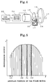
- Fig. 4 is a block diagram of a conventional plunger driving system of a plunger pump.
- Fig. 5 is a graph showing the response results around the peak-top of the output signal from the photosensor.
- the plunger pump is comprised of a plunger driving section, a pump block and a plunger position detecting section.
- the plunger driving section is provided in a case 30, in which a cam 10 fixed on a motor shaft 14, a crosshead 32 equipped with a cam follower 34, and a plunger 36 with a plunger head 38 are included. Between the plunger head 38 and an end wall 40 of the case 30 is provided a spring 42. A pin 44 is inserted into a side face of the crosshead 32 and passes through an opening 46 of the case 30 to prevent it from rotating. The opening 46 is formed lengthy in the axial direction of the case 30 to allow movement of the crosshead 32 in that direction.
- the pump block 50 is attached at the end of the case 30 that the plunger 36 penetrates. Inside of the pump block 50 is comprised of a formed inlet 53, a flow path 52, a cylinder 58, and an outlet 54. The plunger 36 penetrating from the case 30 is inserted in the cylinder 58, and the cylinder 58 joins the flow path 52 at the other end. A pair of check valves 55 and 56 are provided between inlet 53 and the joint, and between the joint and the outlet 54, respectively.
- the plunger position detecting section is illustrated in Figs. 2 and 3.
- a reflector 60 is fixed to the pin 44 extruding from the opening 46 of the case 30, and a support 64 is fixed on the outer wall of the case 30 on which a reflection type photosensor 62 is fixed at the same level as the reflector 60.
- the width of the receiving section 63 of the photosensor 62 is about 2-3 mm.
- the photosensor 62 is fixed at such a position that the light generated by the photosensor 62 is reflected by the reflector 60 at the outermost dead center of the plunger 36 and comes back to the photosensor 62.
- the amount of light reflected from the reflector 60 changes with the corresponding movement of the crosshead 32 or the plunger 36.
- a corner of the reflector 60 is cut off obliquely to enhance the change in the amount of light received by the photosensor 62 in response to the movement of the reflector 60 (or the plunger 36).
- the plunger position detecting section includes an A/D converter 66, motor controller 68 and a motor driver 24, as shown in Fig. 3.
- the motor controller 68 first gives a procession command to the motor driver 24, which sends a preset number of pulses to the pulse motor 12. According to the number of pulses, the angular position ⁇ of the pulse motor 12 rotates by a small preset value ⁇ . Meanwhile the photosensor 62 generates a signal corresponding to the amount of light received from the reflector 60. The signal is converted into digital data by the A/D converter 66, which is given to the motor controller 68 and is stored in a memory provided within the motor controller 68. The motor controller 68 then gives another procession command to the motor driver 24 and further rotates the pulse motor 12 by the small preset value ⁇ , by which another set of digital data is stored in the memory.
- the motor controller 68 After repeating the process until the pulse motor 12 rotates by one turn, the motor controller 68 reads out the data compiled in the memory and selects a preset amount of data associated with the maximum output signal of the photosensor 62. Based on the selected data and according to a preset procedure, the motor controller 68 detects the outermost dead center of the plunger 36. The angular position of the pulse motor 12 at the detected outermost dead center is determined as the reference angular position described above, and is stored in a non-volatile memory.
- the speed/position control of the pulse motor 12, the control of the pump and the control of the HPLC are based on the timing counted from the time point at which the angular position of the pulse motor 12 passes the reference angular position.
- the resolution of the A/D converter 66 should be determined appropriately according to the required preciseness of the determination of the dead center of the plunger 36.
- the small preset value ⁇ for the stepwise procession of the pulse motor 12 should be determined according to the resolution of the A/D converter 66. It is highly recommended that the value of ⁇ be determined so that the change in the output signal of the photosensor is smaller than the resolution of the A/D converter 66 around the peak-top of the outermost dead center of the plunger and therefore there is no change in the converted digital data around the peak-top.
- Fig. 5 An example of determining the dead center of the plunger 36 described above is detailed here referring to Fig. 5.
- the cam profile around the outermost dead center is composed of continuous curves of the second order.
- the curves are asymmetrical before and after the dead center, and the change rate of the curve after the dead center is C0 compared to that after the dead center 1.
- Fig. 5 shows the detail about the peak-top of the curve of change in the A/D converted data representing the output signal I( ⁇ ).
- An angular position ⁇ b0 is defined as the minimum among the three consecutive data whose values I( ⁇ ) do not increase.
- the angular position ⁇ b0 is referred to as the beginning of the flat region.
- Another angular position ⁇ c0 is defined as the minimum among the three data whose values I( ⁇ ) decrease consecutively.
- the angular position ⁇ c0 is referred to as the end of the flat region.
- the reference angular position ⁇ a corresponding to the outermost dead center of the plunger 36 exists between the angular positions ⁇ b0 and ⁇ c0.
- the cam profile is supposed to be composed of continuous curves of the second order, it is also possible to determined the reference angular position ⁇ a by the above method if the cam profile is composed of curves of the same kind and same order around the outermost dead center.
Landscapes
- Engineering & Computer Science (AREA)
- General Engineering & Computer Science (AREA)
- Mechanical Engineering (AREA)
- Analytical Chemistry (AREA)
- General Health & Medical Sciences (AREA)
- Health & Medical Sciences (AREA)
- Life Sciences & Earth Sciences (AREA)
- Chemical & Material Sciences (AREA)
- Computer Hardware Design (AREA)
- Biochemistry (AREA)
- Physics & Mathematics (AREA)
- General Physics & Mathematics (AREA)
- Immunology (AREA)
- Pathology (AREA)
- Control Of Positive-Displacement Pumps (AREA)
- Investigating Or Analysing Materials By Optical Means (AREA)
- Treatment Of Liquids With Adsorbents In General (AREA)
Abstract
A plunger pump according to the present invention includes: a pulse motor for driving a plunger of the plunger pump; a position sensor for detecting the position of the plunger and for generating a position signal corresponding to the position detected; and a reference position detector for detecting the reference position of the pulse motor at which the plunger is at the dead center (the outermost dead center or the innermost dead center) based on a plurality of the position signals from the position sensor. While, in the adjusting operation, the plunger of the plunger pump is moved by the pulse motor, the position sensor sends a series of position signals to the reference position detector. Based on the position signals, especially those around a turning point of the movement of the plunger, the reference position detector detects the exact position of the dead center of the plunger pump, and determines it as the reference position of the pulse motor. In a subsequent HPLC analysis using the plunger pump, the rotational position and speed of the pulse motor are controlled based on the reference position thus determined. The reference position may be further used in various aspects of analysis: in a low pressure gradient elusion, for example, the valves are controlled according to the timing based on the reference position of the pulse motor.
Description
- The present invention relates to a plunger pump for a high performance liquid chromatograph (HPLC).
- When a high performance liquid chromatography (HPLC) is conducted, it is important to supply the mobile phase, or solvent, to the column precisely and constantly. Accordingly, a plunger pump is used in HPLCs because the plunger pump is better at controlling a flow more precisely. When a higher stability in the flow rate is required, two or more plunger pumps are used in combination to cancel pulsations in the output of each plunger pump. When, on the other hand, a high stability is not required, a damper is provided after a plunger pump to absorb pulsations. In this case, the profile of the cam of the plunger pump is designed so that the suction cycle is set shorter while the discharge cycle is set longer in order to minimize the pulsations in the discharged solvent.
- When a precise control of a plunger pump is desired, it is necessary to determine the dead centers of the plunger (i.e., the point at which the plunger is outermost from the cylinder and the point at which the plunger is innermost in the cylinder) precisely. A method of determining the dead centers of a conventional plunger pump is explained referring to Fig. 4.
- The
cam 10 of a plunger pump is fixed on theshaft 14 of apulse motor 12, and a photo-interrupter 16 is also fixed on themotor shaft 14. Anotch 17 is formed in a periphery of the photo-interrupter 16, and an arrangement of a photo-emitter 18 and a photo-receiver 20 are fixed beside the photo-interrupter 16 so that thenotch 17 comes between them. The photo-emitter 18, photo-receiver 20 and the photo-interrupter 16 constitute a photo-sensor which sends a rotation signal to acontroller 22 once in a rotation of the photo-interrupter 16, or once in a rotation of thecam 10. Based on the signal from the photosensor, thecontroller 22 knows the position of thepulse motor 12 and the plunger, and gives a motor control signal to amotor driver 24. Responsive to the motor control signal, themotor driver 24 drives thepulse motor 12 according to the position and speed indicated by the motor control signal. - Generally, in the above construction, the position of the
notch 17 in the photo-interrupter 16 and a dead center of the plunger can not be coincided precisely. Thecontroller 22 therefore determines a reference angular position of the pulse motor 12 (where the plunger is at a dead center) by the position at the time when a preset number of pulses come since the signal from the photosensor came. - The number of the pulses for determining the reference angular position must be predetermined beforehand in the final adjusting stage of manufacturing. Such an adjusting operation for determining the number of pulses is also necessary in performing maintenance of the plunger pump when the cam is replaced with a new one. Such an adjustment requires a considerable amount of labor and time so that efficiency of the manufacturing and the maintenance of the plunger pump is greatly reduced.
- As described above, there is no means to directly detect that the plunger is at a dead center in the conventional plunger pumps. Some error is thus inevitable when setting the plunger at a dead center, which inherently leads to an error in determining the reference angular position of the
pulse motor 12. When a low pressure gradient elusion, for example, is conducted based on the reference angular position including such an error, the concentration of the solvent is not properly controlled and therefore the analysis suffers with low precision. - An object of the present invention is, therefore, to provide a plunger pump suitably used for an HPLC which can detect a dead center precisely without laborious or time-consuming adjusting operations.
- A plunger pump according to the present invention includes:
- a pulse motor for driving a plunger of the plunger pump;
- a position sensor for detecting a position of the plunger and for generating a position signal corresponding to the position detected; and
- a reference position detector for detecting a reference position of the pulse motor at which the plunger is at a dead center based on a plurality of the position signals from the position sensor.
- While, in the adjusting operation, the plunger of the plunger pump is moved by the pulse motor, the position sensor sends a series of position signals to the reference position detector. Based on the position signals, especially those around a turning point of the movement of the plunger, the reference position detector detects the exact position of a dead center (the outermost dead center or the innermost dead center) of the plunger pump, and determines it as the reference position of the pulse motor. In a subsequent HPLC analysis using the plunger pump, the rotational position and speed of the pulse motor are controlled based on the reference position thus determined. The reference position may be further used in various aspects of analysis: in a low pressure gradient elusion, for example, the valves are controlled according to the timing based on the reference position of the pulse motor.
- An example of the position sensor is a reflector linked to the plunger of the plunger pump (i.e., moves with the plunger), and a reflection type photosensor composed of a photo-emitter and a photo-receiver linked to the case or the body of the plunger pump. As the plunger moves, the amount of light reflected by the reflector and received by the photo-receiver changes according to the movement of the plunger. The photosensor thus generates a position signal representing the position of the plunger. Another example is a magnet linked to the plunger and a magnetic field sensor linked to the body of the plunger pump.
- The reference position detector can be constituted by a microcomputer and a program turning on the microcomputer. The content of the program will be shown later in the description of the embodiment.
- According to the present invention, the dead center of the plunger pump can be detected more precisely than conventional ones. When the present invention is applied to a double plunger pump, the working timings of the two plunger pumps are controlled more precisely and the pulsation in the discharged solvent is further decreased. When the plunger pump of the present invention is used in a low pressure gradient elusion, the timings of the valve control become more exact and the solvents are mixed precisely as scheduled.
- Since the reference position is determined automatically by the reference position detector, the adjusting operation becomes very easy and can be done in a shorter period of time. This reduces the manufacturing cost of the plunger pumps, and a greatly facilitates the maintenance of the plunger pumps.
- Fig. 1 is a longitudinal cross-sectional view of a plunger pump embodying the present invention.
- Fig. 2 is a perspective view of the photosensor and the reflector at the outside of the case of the plunger pump.
- Fig. 3 is a block diagram of the plunger position detecting section of the plunger pump.
- Fig. 4 is a block diagram of a conventional plunger driving system of a plunger pump.
- Fig. 5 is a graph showing the response results around the peak-top of the output signal from the photosensor.
- A plunger pump embodying the present invention is described referring to Fig. 1. The plunger pump is comprised of a plunger driving section, a pump block and a plunger position detecting section.
- The plunger driving section is provided in a
case 30, in which acam 10 fixed on amotor shaft 14, acrosshead 32 equipped with acam follower 34, and aplunger 36 with aplunger head 38 are included. Between theplunger head 38 and anend wall 40 of thecase 30 is provided aspring 42. Apin 44 is inserted into a side face of thecrosshead 32 and passes through anopening 46 of thecase 30 to prevent it from rotating. Theopening 46 is formed lengthy in the axial direction of thecase 30 to allow movement of thecrosshead 32 in that direction. - The
pump block 50 is attached at the end of thecase 30 that theplunger 36 penetrates. Inside of thepump block 50 is comprised of a formed inlet 53, aflow path 52, acylinder 58, and anoutlet 54. Theplunger 36 penetrating from thecase 30 is inserted in thecylinder 58, and thecylinder 58 joins theflow path 52 at the other end. A pair ofcheck valves outlet 54, respectively. - The plunger position detecting section is illustrated in Figs. 2 and 3. A
reflector 60 is fixed to thepin 44 extruding from theopening 46 of thecase 30, and asupport 64 is fixed on the outer wall of thecase 30 on which areflection type photosensor 62 is fixed at the same level as thereflector 60. The width of thereceiving section 63 of thephotosensor 62 is about 2-3 mm. Thephotosensor 62 is fixed at such a position that the light generated by thephotosensor 62 is reflected by thereflector 60 at the outermost dead center of theplunger 36 and comes back to thephotosensor 62. Around that position of the plunger 36 (or of the crosshead 32), the amount of light reflected from thereflector 60 changes with the corresponding movement of thecrosshead 32 or theplunger 36. - As shown in Fig. 2, a corner of the
reflector 60 is cut off obliquely to enhance the change in the amount of light received by the photosensor 62 in response to the movement of the reflector 60 (or the plunger 36). - Besides the
photosensor 62 and thereflector 60, the plunger position detecting section includes an A/D converter 66,motor controller 68 and amotor driver 24, as shown in Fig. 3. - The adjusting operation on the pump as described above is now explained. The
motor controller 68 first gives a procession command to themotor driver 24, which sends a preset number of pulses to thepulse motor 12. According to the number of pulses, the angular position θ of thepulse motor 12 rotates by a small preset value Δθ. Meanwhile thephotosensor 62 generates a signal corresponding to the amount of light received from thereflector 60. The signal is converted into digital data by the A/D converter 66, which is given to themotor controller 68 and is stored in a memory provided within themotor controller 68. Themotor controller 68 then gives another procession command to themotor driver 24 and further rotates thepulse motor 12 by the small preset value Δθ, by which another set of digital data is stored in the memory. - After repeating the process until the
pulse motor 12 rotates by one turn, themotor controller 68 reads out the data compiled in the memory and selects a preset amount of data associated with the maximum output signal of thephotosensor 62. Based on the selected data and according to a preset procedure, themotor controller 68 detects the outermost dead center of theplunger 36. The angular position of thepulse motor 12 at the detected outermost dead center is determined as the reference angular position described above, and is stored in a non-volatile memory. - The speed/position control of the
pulse motor 12, the control of the pump and the control of the HPLC (e.g., the timing control of valves for a log pressure gradient elusion) are based on the timing counted from the time point at which the angular position of thepulse motor 12 passes the reference angular position. - The resolution of the A/D converter 66 should be determined appropriately according to the required preciseness of the determination of the dead center of the
plunger 36. The small preset value Δθ for the stepwise procession of thepulse motor 12 should be determined according to the resolution of the A/D converter 66. It is highly recommended that the value of Δθ be determined so that the change in the output signal of the photosensor is smaller than the resolution of the A/D converter 66 around the peak-top of the outermost dead center of the plunger and therefore there is no change in the converted digital data around the peak-top. - An example of determining the dead center of the
plunger 36 described above is detailed here referring to Fig. 5. Suppose in this case that the cam profile around the outermost dead center is composed of continuous curves of the second order. The curves are asymmetrical before and after the dead center, and the change rate of the curve after the dead center is C0 compared to that after the dead center 1. - Fig. 5 shows the detail about the peak-top of the curve of change in the A/D converted data representing the output signal I(θ). An angular position θb0 is defined as the minimum among the three consecutive data whose values I(θ) do not increase. The angular position θb0 is referred to as the beginning of the flat region. Another angular position θc0 is defined as the minimum among the three data whose values I(θ) decrease consecutively. The angular position θc0 is referred to as the end of the flat region. The reference angular position θa corresponding to the outermost dead center of the
plunger 36 exists between the angular positions θb0 and θc0. - An example of the procedure that the
motor controller 68 determines the reference angular position θa is as follows. After determining the angular positions θb0 and θc0 as above, the larger one (or no smaller one) is defined as Imax. Using the angular positions θb0 and n angular positions θb1 to θbn preceding θb0, a series of values ybi are calculated as


- Using the two sets of 2×(n + 1) pieces of data (y, θ), the coefficients C1, C2 and C3 in the formula


- Though, in the above example, the cam profile is supposed to be composed of continuous curves of the second order, it is also possible to determined the reference angular position θa by the above method if the cam profile is composed of curves of the same kind and same order around the outermost dead center.
Claims (6)
- A plunger pump for a liquid chromatograph comprising:a pulse motor for driving a plunger of the plunger pump;a position sensor for detecting a position of the plunger and for generating a position signal corresponding to the position detected; andreference position detecting means for detecting a reference position of the pulse motor at which the plunger is at a dead center based on a plurality of the position signals from the position sensor.
- The plunger pump according to claim 1, wherein:the position sensor generates an analog position signal corresponding to the position detected;an A/D converter is provided between the position sensor and the reference position detecting means for converting the analog position signal into a digital position data; andthe reference position detecting means detect the reference position based on a plurality of the position data obtained while the plunger moves across the dead center.
- The plunger pump according to claim 2, wherein the position sensor comprises:a reflector linked to the plunger; anda photosensor for emitting a light, for receiving the light reflected by the reflector, and for generating the analog position signal corresponding to the amount of light received.
- The plunger pump according to claim 3, wherein a part of the reflector is cut off obliquely to enhance the change in the amount of light received by the photosensor responsive to the movement of the plunger.
- The plunger pump according to claim 2, wherein the reference position detecting means detects the reference position by steps of:selecting a series of position data around the dead center;constructing a curve of the same kind as a curve of a cam profile of a cam of the plunger pump for pushing the plunger based on the selected position data; anddetermining the reference position as the maximum or minimum point of the constructed curve.
- The plunger pump according to claim 5, wherein the resolution of the A/D converter is set so that values of a plurality of position data are the same around the dead center.
Applications Claiming Priority (2)
| Application Number | Priority Date | Filing Date | Title |
|---|---|---|---|
| JP104283/96 | 1996-03-29 | ||
| JP10428396A JP3449113B2 (en) | 1996-03-29 | 1996-03-29 | Liquid sending device for liquid chromatograph |
Publications (2)
| Publication Number | Publication Date |
|---|---|
| EP0798558A2 true EP0798558A2 (en) | 1997-10-01 |
| EP0798558A3 EP0798558A3 (en) | 1998-08-19 |
Family
ID=14376609
Family Applications (1)
| Application Number | Title | Priority Date | Filing Date |
|---|---|---|---|
| EP97105308A Withdrawn EP0798558A3 (en) | 1996-03-29 | 1997-03-27 | Plunger pump for a high performance liquid chromatograph |
Country Status (2)
| Country | Link |
|---|---|
| EP (1) | EP0798558A3 (en) |
| JP (1) | JP3449113B2 (en) |
Cited By (11)
| Publication number | Priority date | Publication date | Assignee | Title |
|---|---|---|---|---|
| EP1754891A2 (en) | 2005-08-19 | 2007-02-21 | ProMinent Dosiertechnik GmbH | Dosing pump |
| WO2011050586A1 (en) * | 2009-10-30 | 2011-05-05 | 北京普析通用仪器有限责任公司 | Serial-parallel liquid-phase chromatographic pump |
| WO2011116633A1 (en) * | 2010-03-23 | 2011-09-29 | 北京普析通用仪器有限责任公司 | Liquid path distributing valve and liquid-phase chromatographic pump comprising the same |
| US8267667B2 (en) * | 2005-08-22 | 2012-09-18 | Prominent Dosiertechnik Gmbh | Magnetic drive metering pump |
| EP2515970A1 (en) * | 2009-12-23 | 2012-10-31 | Jean-Denis Rochat | Alternating positive-displacement pump having a membrane for medical use |
| CN102953965A (en) * | 2012-10-25 | 2013-03-06 | 安徽皖仪科技股份有限公司 | High-voltage and constant-current pump using electronic cam technique to realize constant-current liquid conveying function |
| DE102012214385A1 (en) * | 2012-08-13 | 2014-02-13 | Zf Friedrichshafen Ag | Device for moving a piston of adjustable radial piston engine, has sensor device that is provided to determine amplitude of movement of piston based on the changing amplitude of scanning size |
| CN106762572A (en) * | 2017-01-17 | 2017-05-31 | 无锡市天利流体科技有限公司 | Intelligent filling pump |
| CN107642472A (en) * | 2016-07-20 | 2018-01-30 | 北京普源精电科技有限公司 | Infusion pump and its self-test repositioning method with self-protection function |
| GB2555816A (en) * | 2016-11-10 | 2018-05-16 | Natural Environment Res Council | Analyser |
| CN110741252A (en) * | 2017-09-01 | 2020-01-31 | 株式会社岛津制作所 | Switching valve |
Families Citing this family (1)
| Publication number | Priority date | Publication date | Assignee | Title |
|---|---|---|---|---|
| CN101245770B (en) * | 2007-02-17 | 2012-05-30 | 卓越剂量技术有限公司 | Electromotor driven metering pump |
Citations (4)
| Publication number | Priority date | Publication date | Assignee | Title |
|---|---|---|---|---|
| US3981620A (en) * | 1972-03-06 | 1976-09-21 | Waters Associates, Inc. | Pumping apparatus |
| US4797834A (en) * | 1986-09-30 | 1989-01-10 | Honganen Ronald E | Process for controlling a pump to account for compressibility of liquids in obtaining steady flow |
| US4832575A (en) * | 1988-01-11 | 1989-05-23 | Spectra Physics | Automatic test system for check valve closure in pump for liquid chromatography system |
| US5457626A (en) * | 1994-09-01 | 1995-10-10 | Dionex Corporation | Bimodal liquid chromatography pump employing artificial intelligence logic feedback control |
-
1996
- 1996-03-29 JP JP10428396A patent/JP3449113B2/en not_active Expired - Fee Related
-
1997
- 1997-03-27 EP EP97105308A patent/EP0798558A3/en not_active Withdrawn
Patent Citations (4)
| Publication number | Priority date | Publication date | Assignee | Title |
|---|---|---|---|---|
| US3981620A (en) * | 1972-03-06 | 1976-09-21 | Waters Associates, Inc. | Pumping apparatus |
| US4797834A (en) * | 1986-09-30 | 1989-01-10 | Honganen Ronald E | Process for controlling a pump to account for compressibility of liquids in obtaining steady flow |
| US4832575A (en) * | 1988-01-11 | 1989-05-23 | Spectra Physics | Automatic test system for check valve closure in pump for liquid chromatography system |
| US5457626A (en) * | 1994-09-01 | 1995-10-10 | Dionex Corporation | Bimodal liquid chromatography pump employing artificial intelligence logic feedback control |
Cited By (13)
| Publication number | Priority date | Publication date | Assignee | Title |
|---|---|---|---|---|
| EP1754891A3 (en) * | 2005-08-19 | 2008-08-20 | ProMinent Dosiertechnik GmbH | Dosing pump |
| EP1754891A2 (en) | 2005-08-19 | 2007-02-21 | ProMinent Dosiertechnik GmbH | Dosing pump |
| US8267667B2 (en) * | 2005-08-22 | 2012-09-18 | Prominent Dosiertechnik Gmbh | Magnetic drive metering pump |
| WO2011050586A1 (en) * | 2009-10-30 | 2011-05-05 | 北京普析通用仪器有限责任公司 | Serial-parallel liquid-phase chromatographic pump |
| CN102052276B (en) * | 2009-10-30 | 2013-09-11 | 北京普析通用仪器有限责任公司 | Series-parallel connection liquid chromatogram pump |
| EP2515970A1 (en) * | 2009-12-23 | 2012-10-31 | Jean-Denis Rochat | Alternating positive-displacement pump having a membrane for medical use |
| WO2011116633A1 (en) * | 2010-03-23 | 2011-09-29 | 北京普析通用仪器有限责任公司 | Liquid path distributing valve and liquid-phase chromatographic pump comprising the same |
| DE102012214385A1 (en) * | 2012-08-13 | 2014-02-13 | Zf Friedrichshafen Ag | Device for moving a piston of adjustable radial piston engine, has sensor device that is provided to determine amplitude of movement of piston based on the changing amplitude of scanning size |
| CN102953965A (en) * | 2012-10-25 | 2013-03-06 | 安徽皖仪科技股份有限公司 | High-voltage and constant-current pump using electronic cam technique to realize constant-current liquid conveying function |
| CN107642472A (en) * | 2016-07-20 | 2018-01-30 | 北京普源精电科技有限公司 | Infusion pump and its self-test repositioning method with self-protection function |
| GB2555816A (en) * | 2016-11-10 | 2018-05-16 | Natural Environment Res Council | Analyser |
| CN106762572A (en) * | 2017-01-17 | 2017-05-31 | 无锡市天利流体科技有限公司 | Intelligent filling pump |
| CN110741252A (en) * | 2017-09-01 | 2020-01-31 | 株式会社岛津制作所 | Switching valve |
Also Published As
| Publication number | Publication date |
|---|---|
| JPH09269318A (en) | 1997-10-14 |
| EP0798558A3 (en) | 1998-08-19 |
| JP3449113B2 (en) | 2003-09-22 |
Similar Documents
| Publication | Publication Date | Title |
|---|---|---|
| US4913624A (en) | Low pulsation displacement pump | |
| EP0798558A2 (en) | Plunger pump for a high performance liquid chromatograph | |
| US4797834A (en) | Process for controlling a pump to account for compressibility of liquids in obtaining steady flow | |
| US7037081B2 (en) | High pressure reciprocating pump and control of the same | |
| US4352636A (en) | Dual piston pump | |
| JP2604362B2 (en) | Low pulsation pump | |
| US5664937A (en) | Precisely flow-controlling pump | |
| JP3218231B2 (en) | Pump device | |
| JP3172429B2 (en) | Liquid chromatograph | |
| US20110042283A1 (en) | Liquid delivery device, liquid chromatograph, and method for operation of liquid delivery device | |
| US4552513A (en) | Multiple piston pump control | |
| EP0334994B1 (en) | Reciprocating type fluid delivery pump | |
| US4797207A (en) | Apparatus for controlling a pump to account for compressibility of liquids in obtaining steady flow | |
| US4752385A (en) | Liquid chromatograph | |
| US6860137B2 (en) | Liquid transfer device, control method of liquid mixing ratio thereof and liquid chromatograph with liquid transfer device | |
| JP3117623B2 (en) | Multiple fluid mixing pump device | |
| JPH0219670A (en) | Control method for nonpulsating pump | |
| JPS636758B2 (en) | ||
| JPH02201071A (en) | Liquid delivery device | |
| JPS63168557A (en) | Liquid feeder | |
| JPH02147953A (en) | Liquid sending apparatus | |
| JPH10311824A (en) | Multiple fluid mixing pump device | |
| JPH06146327A (en) | Working machine control device for construction machine | |
| JPH02176174A (en) | Control method for non-pulsating pump | |
| JPS63205133A (en) | Liquid feed device |
Legal Events
| Date | Code | Title | Description |
|---|---|---|---|
| PUAI | Public reference made under article 153(3) epc to a published international application that has entered the european phase |
Free format text: ORIGINAL CODE: 0009012 |
|
| AK | Designated contracting states |
Kind code of ref document: A2 Designated state(s): DE FR GB |
|
| PUAL | Search report despatched |
Free format text: ORIGINAL CODE: 0009013 |
|
| AK | Designated contracting states |
Kind code of ref document: A3 Designated state(s): DE FR GB |
|
| STAA | Information on the status of an ep patent application or granted ep patent |
Free format text: STATUS: THE APPLICATION IS DEEMED TO BE WITHDRAWN |
|
| 18D | Application deemed to be withdrawn |
Effective date: 19990220 |